Table of Contents
Advertisement
Quick Links
Assembly and operating instructions
DULCOTEST Sensor for Peracetic Acid
Type PAA 2-3E
EN
A3251
Please carefully read these operating instructions before use. · Do not discard.
The operator shall be liable for any damage caused by installation or operating errors.
The latest version of the operating instructions are available on our homepage.
Part number 999574
Version: BA DT 069 01/22 EN
Advertisement
Table of Contents
Troubleshooting

Related Manuals for ProMinent DULCOTEST PAA 2-3E


Summary of Contents for ProMinent DULCOTEST PAA 2-3E
- Page 1 Assembly and operating instructions DULCOTEST Sensor for Peracetic Acid Type PAA 2-3E A3251 Please carefully read these operating instructions before use. · Do not discard. The operator shall be liable for any damage caused by installation or operating errors. The latest version of the operating instructions are available on our homepage. Part number 999574 Version: BA DT 069 01/22 EN...
- Page 2 Supplemental directives General non-discriminatory approach In order to make it easier to read, this document uses the male form in grammat‐ ical structures but with an implied neutral sense. The document is always aimed equally at women, men and gender-neu‐ tral persons.
- Page 3 Supplemental directives Symbol Description ‘Display/GUI’ Screen elements (e.g. buttons, assignment of function keys). Presentation of software elements and/or texts. CODE...
-
Page 4: Table Of Contents
Table of contents Table of contents Introduction......................6 1.1 Functional description..................7 1.2 Construction....................8 Safety........................10 2.1 Labelling of Warning Information..............10 2.2 User qualification..................12 2.3 General safety information................13 2.4 Intended use....................14 2.5 Information in the event of an emergency............ 14 Storage and transport of the sensor.............. - Page 5 Table of contents Index........................39...
-
Page 6: Introduction
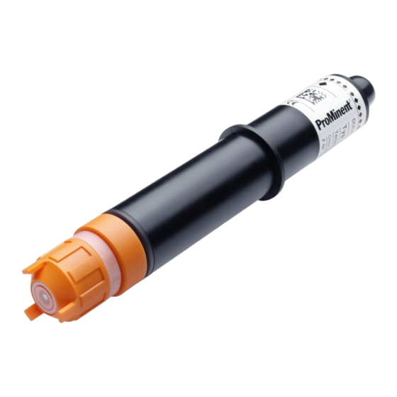
Introduction Introduction These operating instructions provide information on the technical data and functions of the DULCOTEST sensor for peracetic acid, type PAA 2 A3253 Fig. 1: DULCOTEST sensor for peracetic acid, type PAA 2 Sensor Order number PAA 2-3E-mA-20 ppm 1119538 PAA 2-3E-mA-2 ppm 1120263... -
Page 7: Functional Description
Introduction Functional description Brief description of the function Parameter Value Measured variable Peracetic acid (C Measuring range: 0.2 ... 20 mg/l pH-range: 5.5 ... 8.0 The sensor is a diaphragm-covered, amperometric three-electrode sensor. The sensor can be used to determine the concentration of peracetic acid in water. A platinum cathode acts as a working electrode and a silver halide-coated anode acts as a counter and reference electrode The peracetic acid contained in the sample water diffuses through the diaphragm. -
Page 8: Construction
Introduction Construction B1314 Fig. 2: The construction of the sensor O-ring seal O-ring seal Counter electrode (silver) Electrode shaft Reference electrode (grey) 10 Clamp disc Working electrode (golden) 11 2-wire connector Diaphragm protective cap 12 Top part Diaphragm cap 13 Cable feed-through, M12 threaded Hose seal connector... - Page 9 Introduction Construction The sensor consists of 3 main compo‐ nents: the top part, the electrode shaft and the diaphragm cap. The diaphragm cap, filled with electrolyte, constitutes the measuring chamber, into which the meas‐ uring electrodes are immersed. The measuring chamber is sealed from the measuring medium by a microporous dia‐...
-
Page 10: Safety
Safety Safety Labelling of Warning Infor‐ mation WARNING! Introduction Nature and source of the danger These operating instructions provide infor‐ Possible consequence: Fatal or mation on the technical data and functions very serious injuries. of the product. These operating instruc‐ Measure to be taken to avoid this tions provide detailed warning information danger. - Page 11 Safety NOTICE! Nature and source of the danger Damage to the product or its sur‐ roundings. Measure to be taken to avoid this danger. – Denotes a possibly damaging situation. If the situation is dis‐ regarded, the product or an object in its vicinity could be damaged.
-
Page 12: User Qualification
Safety User qualification WARNING! Danger of injury with inadequately qualified personnel The operator of the system / equipment is responsible for ensuring that the qualifi‐ cations are fulfilled. If inadequately qualified personnel work on the unit or loiter in the hazard zone of the unit, this could result in dangers that could cause serious injuries and material damage. -
Page 13: General Safety Information
Safety Training Definition Electrical technician An electrical technician is able to complete work on electrical systems and recognise and avoid possible dangers independ‐ ently based on his technical training and experience as well as knowledge of pertinent standards and regulations. An electrical technician must be able to perform the tasks assigned to him independently with the assistance of drawing documentation, parts lists, terminal and circuit diagrams. -
Page 14: Intended Use
(> 24 h). Intended use Intended use: Only use the sensor to measure and regulate concentrations of peracetic acid. Connection to external controllers requires the approval of ProMinent. The sensor is not a safety compo‐ nent. -
Page 15: Storage And Transport Of The Sensor
Storage and transport of the sensor Storage and transport of the sensor Transport User qualification: instructed user Ä Chapter 2.2 ‘User qualification’ Only transport the sensor in its original on page 12 packaging and in compliance with the per‐ missible environmental conditions. No fur‐ ther special conditions have to be Original packaging observed in relation to transport. -
Page 16: Assembly
Assembly Assembly User qualification: trained user Do not store electrolyte beyond its Ä Chapter 2.2 ‘User qualification’ "Use by" date and note the "Use by" on page 12 date on the label of the electrolyte bottle. Pour in the electrolyte, preferably free WARNING! of bubbles. -
Page 17: Filling Electrolyte
Assembly Filling electrolyte Open the electrolyte bottle and screw on the nozzle. A2418 Fig. 3: Fill the electrolyte. Diaphragm cap Filling height of the electrolyte Nozzle Vent hole Pour in the electrolyte, preferably free of bubbles. - Page 18 Assembly Place the electrolyte bottle on the diaphragm cap and slowly press the electrolyte in a single stream from the electrolyte bottle, at the same time evenly pulling back the electrolyte bottle. ð The cap is completely full when the electrolyte can be seen at the bottom thread.
-
Page 19: Installing The Sensor In The Bypass Fitting
Only use the sensor in ProMinent bypass fittings. Use appropriate measuring – methods to check the measured results before commissioning if using other bypass fittings. - Page 20 Assembly A0645 Fig. 4: Installation situation Threaded sleeve Clamp disc Sensor O-ring Washer Bypass fitting e.g. DLG Push the O-ring (4) and the washer (5) included in the mounting kit from below over the sensor as far as the clamp disc (2). Bypass fitting DLG III: guide the sensor into the DLG III and tighten the threaded sleeve.
-
Page 21: Installation
Installation Installation Ä Chapter 2.2 User qualification: trained qualified personnel or electrical technician, ‘User qualification’ on page 12 WARNING! Sensor connector on external equipment Possible consequence: fatal or very serious injuries. – Ensure that the connected controller is galvanically isolated from the sensor. –... - Page 22 Installation Electrical installation Turn the top part (1) of the sensor a quarter turn anticlockwise and remove the top part. Loosen the clamping nut (2) from the M12 threaded connector and feed the meas‐ uring line (3) through the clamping nut. A2419 Fig.
-
Page 23: Starting Up The Sensor
Starting up the sensor Starting up the sensor User qualification: trained user Ä Chapter 2.2 ‘User qualification’ CAUTION! on page 12 – Do not disconnect the power supply to the controller and WARNING! sensor. Recommission fol‐ lowing longer interruptions to Danger from hazardous sub‐... -
Page 24: Discontinuous Operation
Starting up the sensor The controller can be switched on once With longer idle times (4 ... 14 days), installation has been completed. You have it is mandatory to replace the feed to wait for the run-in period of the sensor. chemical in the bypass fitting with water at the end of the rinsing process. -
Page 25: Allowing The Sensor To Run In
Starting up the sensor Allowing the sensor to run in Run-in period The sensor requires a specific run-in period to display a steady display value. Initial commissioning: 3 ... 6 h After replacing the diaphragm: Recommissioning: 1 ... 2 h CAUTION! –... - Page 26 Starting up the sensor Slope calibration Using two-stage titration CAUTION! NOTICE! – Check the calibration 24 hours after initial commissioning. Only calibrate if the concentration – Repeat the calibration process of the feed chemical remains con‐ in the event that the concen‐ stant.
- Page 27 Starting up the sensor Using a standard solution Fill a standard solution with a known concentration e.g. into the container of the DLG III bypass fit‐ ting. Stir the contents of the container with a magnetic stirrer. Immerse the sensor in the container until the measured value remains constant, approx.
-
Page 28: Maintaining And Repairing The Sensor
Maintaining and repairing the sensor Maintaining and repairing the sensor User qualification: trained user Maintenance interval Ä Chapter 2.2 ‘User qualification’ Empirical values for CIP (cleaning in on page 12 place): 1 month. Other applications: depending on the operating conditions. WARNING! Maintenance work Danger from hazardous sub‐... -
Page 29: Troubleshooting
Troubleshooting Troubleshooting WARNING! Danger from hazardous sub‐ stances! Possible consequence: Fatal or very serious injuries. Please ensure when handling haz‐ ardous substances that you have read the latest safety data sheets provided by the manufacture of the hazardous substance. The actions required are described in the safety data sheet. -
Page 30: Troubleshooting
Troubleshooting Troubleshooting Sensor: Troubleshooting Consider the complete measuring point when troubleshooting. The measuring point con‐ sists of: Controller Electrical cable and connectors. Bypass fitting and hydraulic connectors. Sensor. The possible causes of faults in the table below principally refer to the sensor. Make sure that the operating conditions have been complied with before commencing trouble‐... - Page 31 Remove the air bubbles by tap‐ the diaphragm. ping and increase the flow, if necessary. Troublesome substances in Contact ProMinent. the sample water. Deposits (manganese, iron Clean or replace the diaphragm oxide) on the diaphragm. cap; allow the sensor to run in, and calibrate it.
- Page 32 Troubleshooting...
-
Page 33: Decommissioning
Decommissioning Decommissioning User qualification: instructed user Decommissioning the sensor Ä Chapter 2.2 ‘User qualification’ Switch off the controller before dis‐ on page 12 mantling the sensor. INFORMATION: Removing the sensor would otherwise produce an WARNING! incorrect measured value at the Danger from hazardous sub‐... -
Page 34: Disposal Of Used Parts
Material Safety Data Sheet for your feed chemical. A current Declaration of Decontamination In accordance with the European Directive is available to download on the ProMinent 2012/19/EU on waste electrical and elec‐ website. tronic equipment, this device features the symbol showing a waste bin with a line through it. -
Page 35: Technical Data
Technical data Technical data Parameter Value Measured variable: Peracetic acid (C Configuration: 3 electrodes Measuring range: 0.2 ... 20.0 mg/l 0.02 ... 2.00 mg/l pH-range: 5.5 ... 8.0 Temperature range: 0 ... 40 °C Temperature compensation: internal compensation. Maximum temperature change: max. -
Page 36: Spare Parts And Accessories
Spare parts and accessories Ordering address for spare parts and accessories: The current address for ordering spare parts and accessories can be found on the manufacturer’s homepage ProMinent. The sensor can only be ordered as a complete kit comprising: 1 sensor. - Page 37 Spare parts and accessories Tab. 2: The following spare parts/consumables and accessories are available for the sen‐ sors: # Designation Order number 1 1 two-core measuring line (2 x 0.25 mm 725122 , Ø 4 mm) 2 1 bottle of electrolyte PAA2, 50 ml 1120350 3 1 diaphragm cap, complete, type CGE2 792862...
-
Page 38: Directives / Standards Adhered To
Directives / standards adhered to Directives / standards adhered to EU directives: EMC Directive (2014/30/EU). RoHS Directive (2011/65/EU). Harmonised standards: EN 61326-1:2013, Class B EN 50581:2012 You will find the EC Declaration of Con‐ formity to download on our homepage. - Page 39 Index Index Installation instructions ... 20 Installation kit ....36 Accessories ....36 Installation situation .
- Page 40 Index Question: What do I need to consider Standards complied with ..38 when decommissioning or disposing of the sensor? ....33 Question: What spare parts/consuma‐...
- Page 44 ProMinent GmbH Im Schuhmachergewann 5 - 11 69123 Heidelberg, Germany Telephone: +49 6221 842-0 Fax: +49 6221 842-419 Email: info@prominent.com Internet: www.prominent.com 999574, 1, en_GB © 2022...
Need help?
Do you have a question about the DULCOTEST PAA 2-3E and is the answer not in the manual?
Questions and answers