
Subscribe to Our Youtube Channel
Related Manuals for Robotis BIOLOID GP


Summary of Contents for Robotis BIOLOID GP
- Page 1 All rights reserved. No part of this book may be reproduced, in any form or by any means, without prior consent or written permission from the publisher.
- Page 2 Attention Exercise safety when using this product, Robotis is not responsible for any accidents due to user negligence. Please read the instructions carefully before getting started. This product may not be suitable for children aged below 15. Do not use any other tools other than the ones provided with the kit.
-
Page 3: Table Of Contents
Table of Contents 1. Components and features 2. Assembly 3. Robot action 4. Participation in robot competition 5. troubleshooting 6. Assembly manual 7. Part list For more information or tutorials go to http://support.robotis.com... -
Page 4: Components And Features
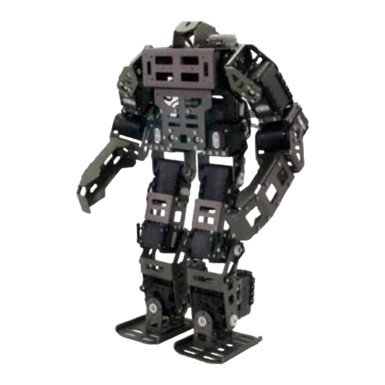
1. Bioloid GP Components and Features AX-12+ : 8 units Remote control (RC-100) - Networked, robot-dedicated servos - Dedicated remote control - Versatile, expandable structure - Upgradeable with Zigbee - Torque : 15kgf·cm(at 12V) - Motion range : 300 degrees... -
Page 5: Assembly
Assembling the robot Please follow the assembly manual during assembly. Remote Control Zigbee Module Try to make the best performance robot with Bioloid GP Gyro sensor for position control High performance Dyanmixel AX-18F Ultra lighted high strength aluminum frame - Weight : 1.6kg, Height : 35cm... -
Page 6: Robot Action
3. Robot Action (1) Turning the robot on ① Turn the power switch on and the LED will start blinking. Press MODE until the PLAY LED starts blinking. MODE ② Press START (ensure PLAY’s LED is blinking). ③ START If the LED does not turn on check the power cable or connection. Ensure the battery pack is properly charged (refer to p.8 (4) fo9r more information) ①... - Page 7 (3) Robot Action buttons are as follows. Soccer Mode Combat Mode The remote control (RC-100) controls the robot. RC-100 Operations Hold the button for 2 seconds to power on. ① POWER/MODE ② The following buttons control the robot. ③ Walking(soccer/combat) : Fast Forward : Forward U + 6...
- Page 8 Combat Mode Walks by default and follows the buttons illustrated below. : forward attack knock : left attack : right attack (4) Charging During robot operation when the battery beeps charge the battery pack immediately. The LED turns on red during charging; switches to green after completion. ①...
-
Page 9: Participation In Robot Competition
4. Participation in robot competition (for more information and tutorials visit the homepage) Competitions Rules Already existing interests, Contest rules and tuning contest participation and compliance registration Conference exhibitions Motion and algorith generation Conference exhibitions Competition-related configurations and algorithm updates. Programming RoboPlus robot programming software for motion creation and robot control. -
Page 10: Troubleshooting
5. Troubleshooting (1) Assembly Robot’s motions are abnormal. Abnormal basic posture Check the assembly of each joint. Robot falls during walk and gait is unstable. The gyroscope sensor is not properly connected. Ensure the gyroscope sensor is properly connected. Do not change the gyroscope cable orientation (refer to Step 18(p.23)). Torque is released and Dynamixel’s LED turn on after a warning beep. - Page 11 Battery power is very low. Recharge the battery pack immediately (refer to page 8). If the robot continues operation under very low power then the robot can suddenly shut down potentially damaging the robot from a fall. For more information refer to Robotis homepage or contact us. User Guide Product Category...
-
Page 12: Assembly Manual
6. Assembly Manual... - Page 14 Dynamixel AX series hinge attachment procedure. Begin with WA. 1. Prepare parts 2. Fasten screws with the horn 3. Insert WA between the frame (WB M2X06) and motor 4. Insert WA into BU 5. Attach to the back side of motor 6.
- Page 15 BIOLOID GP Assembly Start Insert nuts ID1 and ID2 of AX-12+. STEP Connect ID1 and ID2 with CABLE-10, then attach them to chest F(FR04-E120) STEP frame, and then, attach them again to chestB(FR04-E150). Do not misalign horn position during attachment)
- Page 16 Attach chest frame and FR04-H102 frame together.( do not misalign horn position) STEP Insert nut to ID3 and ID4 of AX-12+; afterwards attach them to FR04-SC101 frame. STEP Insert nuts to ID5 and ID6 of AX-12+.
- Page 17 Attach ID3 to ID5 and ID4 to ID6. STEP Attach screw to FR04-E180(hand frame), then attach them (FR04-H102) hinge frame. STEP...
- Page 18 Attach hand to arm, then attach to body frame. STEP refer to tip 1, hand and horn orientation) Attach gyroscope board and FR04-E191 bracket to FR04-E131 back frame. STEP Robot Frontsid Robot Backside Fasten front-sided 2 bolts only...
- Page 19 Attach foor frame and FR04-H101 frame together. STEP Insert nuts to ID15 and ID16 of AX-18F; insert N2 nuts to F7. STEP Afterward attach F7 to DYNAMIXEL.
- Page 20 Insert nuts to ID 17 and ID18 of AX-18F, then attach to FR04-X101 cross frame. STEP Attach foot to DYNAMIXEL then attach to ankle. STEP...
- Page 21 Attach ankle and FR04-H120 foot frame together. ( refer to tip 1) STEP Attach legs and FR04-SC110 frame(with AX-18F) together. STEP...
- Page 22 Attach ID11 and ID12 of AX-18Fto legs; attach each FR04-HC110 frame to ID9 and STEP ID10 of AX-18F, then to attach to legs. Connect ID9 and ID10 with CABLE-14 as shown below. ( refer to tip 1) Attach body and legs together. ( refer to tip 1) STEP...
- Page 23 Attach PR10-SPACER-01 (body’s back) and BATTERY COVER-B (F60) together. STEP Attach the CM-510 controller to FR04-E150 (body back frame), STEP Connect the gyroscope sensor with 5P cable to the CM-510. (Front : CM-510 port 3 / BACK : CM-510 port 4) X axis cable Robot front cable Y axis cable...
- Page 24 Connect ID4 and ID6; ID3 and ID5 with CABLE-10 each pair. Connect ID2 and ID4; STEP ID1 and ID3 with CABLE-18. 1. Connect ID9 to CM-510 and ID10 to CM-510 with CABLE-10. 2. Connect ID9 and ID11; ID10 and ID12 with CABLE-14 each pair. 3.
- Page 25 Following the illustration below organize the wiring with the cable holder (F55). STEP...
- Page 26 Attach head frame and LED Board. ( attention to the direction of 5P-CABLE) STEP Attach head frame to chest frame, the connect a 5P-CABLE to port 5 of the CM-510. CM-510 right side LED BOARD Connect the battery cable (CABLE-BAT) to the CM-510. STEP (Tip : run the CABLE-BAT under the body to main better wiring organization) Connect the other end of CABLE-BAT to the battery pack cable.
- Page 28 28 28...
- Page 29 [Optional gripper mounting] Follow the diagram below illustrates right gripper attachment to ID7 and left gripper attachment to ID8.( refer to tip 1)
Need help?
Do you have a question about the BIOLOID GP and is the answer not in the manual?
Questions and answers