fluenta FGM 160 Operating Instructions Manual
Flare gas meter
Hide thumbs
Also See for FGM 160:
- Maintenance procedures (4 pages) ,
- Installation instructions manual (40 pages) ,
- User manual (34 pages)
Table of Contents
Advertisement
Document number:
Document title:
Scope:
ISO 9001:2015 §8.6 Release of products and services
Additional Information (when applicable):
E
2018.09.17 Updated Abbreviations and removed O&SC
D
2014.01.20 Proofread and updated
Removed from User Manual, updated:
changes in text formatting; modifying
C
2013.01.30
graphics in Appendix II and Electronic
modules
B
2009.06.02 Updated information
Issued for Fluenta release; moved to User
A
2007.11.30
Manual
Rev.
Issue date
index
n/a
Replacement for:
Fluenta source doc.
n/a
(for translations):
72.120.601
FGM 160 Operating Instructions
Reason for issue
AK
NB
MR
JB
AP
CT
MKJ
KH
-
AAJ
RT
N/A
MS
RT
-
Author
Review
Review
MM
MB
MB
MW
MW
MW
N/A
AAJ
N/A
AAJ
Review
Approved
by QA
Total pages:
27
Advertisement
Table of Contents

Related Manuals for fluenta FGM 160


Summary of Contents for fluenta FGM 160
- Page 1 2014.01.20 Proofread and updated Removed from User Manual, updated: changes in text formatting; modifying 2013.01.30 graphics in Appendix II and Electronic modules 2009.06.02 Updated information Issued for Fluenta release; moved to User 2007.11.30 Manual Rev. Review Issue date Reason for issue...
-
Page 2: Table Of Contents
Current Loop Outputs ................5 3.1.4.4 HART Output ..................... 5 3.1.4.5 Pulse/Frequency Output ................5 3.1.5 Electronic Modules in FGM 160................6 3.1.5.1 Digital Signal Processing (DSP) Module ........... 6 3.1.5.2 Analog Front End (AFE) Module ............... 6 3.1.5.3 Pressure & Temperature (P&T) Module ............ 6 3.1.5.4... -
Page 3: Purpose
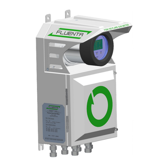
GENERAL INFORMATION 3.1 Hardware Description The FGM 160 Field Computer, illustrated in Figure 1, is designed as a distributed system. The FGM 160 consists of five or six modules, the Digital Signal Processing (DSP) module, the Analog Front End (AFE) module, the Pressure & Temperature (P&T) module, Input/Output (I/O) module, Intrinsic Safe Barrier (IS Barrier) module, Surge Protection module and the Local Display. -
Page 4: Electrical Connections
3.1.2 Power Supply The FGM 160 requires 24 VDC power supply (nominal). If 24 VDC is not available, an optional 110-230 VAC/24 VDC converter can be supplied by Fluenta. For detailed equipment information and equipment ratings, please refer to Hazardous Area Installation Guidelines [1]. -
Page 5: Pressure And Temperature Transmitters
3.1.4.5 Pulse/Frequency Output The FGM 160 can be also configured to provide a pulse or frequency output signal. The pulse output will represent an incrementation of the totalizer (of e.g. volume or mass), whereas the frequency output will represent a process parameter (e.g. volume flow rate, mass flow rate etc.) -
Page 6: Electronic Modules In Fgm 160
3.1.5.4 Input/Output (I/O) Module The Input/Output Module is the interface between the FGM 160 in hazardous areas and equipment in safe areas. At the I/O Module, 24 VDC (nom.) supply voltage is converted to the required operational voltages for the other modules. Furthermore, all signals and communications to and from the DCS system and UFM Manager are handled by this unit. -
Page 7: Non-Resettable Counter Function
FGM 160 Operating Instructions 3.1.6 Non-Resettable Counter Function The non-resettable counter function will record and keep the totalized volume and mass. The totalized values are accessible through the DCS Modbus interface or through UFM Manager. Figure 3 Electronic modules 3.2 Firmware Description In the following sections a general description of the firmware for the different modules is outlined. -
Page 8: P&T Module
Modbus or HART interfaces. 3.3 Device Integrity 3.3.1 Self-Checking The FGM 160 performs a self-checking sequence, where it checks that inputs from the transducers and Temperature and Pressure transmitters are within a valid range, and that other functions are operating as intended. 3.3.2... -
Page 9: Configuration And Operating Software
It should be noted, UFM Manager is required to replace the default settings with actual applicable settings provided by customer. Fluenta service engineers and partners will always set up the FGM 160 according to the latest submitted parameters from the Client when installing and commissioning the FGM 160. Fluenta service engineers and partners always have the UFM Manager with them. -
Page 10: Operating Procedure
24 VDC supply or through a 110-240 VAC/24 VDC converter. 3. Turn on the power to the FGM 160. There is no power switch on the FGM 160 Field Computer, so the power must be switched by an external switch or similar, preferably in safe area. -
Page 11: Local Display Functions
[4]. 4.4 Local Display Functions The FGM 160 is equipped with a local LCD display mounted at the front, and visible through the Ex-d safety glass. The display shows predefined process parameters from the FGM 160. Further, 4 status LEDs are visible at the front for the following status information: •... -
Page 12: Error Check And Troubleshooting
E-mail: support@fluenta.com NOTE! Before any work can be carried out with the FGM 160 field computer, a hot work permit must be obtained. Do not connect or disconnect any signal wires unless the power is turned OFF! Do not open the Ex-d enclosure containing the field electronics in hazardous area, without making sure first that the conditions permit such action. -
Page 13: Error Check With Ufm Manager
4.5.2 Error Check with UFM Manager Through the FGM 160 UFM Manager, data can be logged for trend analysis and evaluation. Figure 5: By pressing the “START Data Logging” button at the “Data Logging” tab, any or most parameters can be logged to a data file. The data log file name will be generated automatically based on the current date and time. -
Page 14: Appendix I - System Configuration File
FGM 160 Operating Instructions APPENDIX I – SYSTEM CONFIGURATION FILE ******************************************************** ******************************************************** ****************** *************** ****************** Fluenta AS *************** ****************** FGM 160 parameter list *************** ****************** *************** ******************************************************** ******************************************************** UFM Manager ver.: 1.040 Field Computer, date and time: 2011-01-17 09:13:25 ***************************************... - Page 15 FGM 160 Operating Instructions HART Output Communication: Enabled Poll address: Primary Variable: Total Volume @ Ref. Conditions Secondary Variable: Volume Flowrate @ Ref. Conditions Tertiary Variable: Temperature Quaternary Variable: Pressure **************** Service port ***************** ------------------------------------------------------------- Slave address: Type: Baud rate:...
- Page 16 FGM 160 Operating Instructions Temperature, scale: 0.9963 Pressure, offset: 0.0220 Pressure, scale: 0.9980 Alarm limits Temperature, Hi limit: 533.15 [Kelvin] Temperature, Lo limit: 255.15 [Kelvin] Pressure, Hi limit: 12.044 [BarA] Pressure, Lo limit: 1.013 [BarA] ********************************************** ********** Output signal parameters **********...
- Page 17 FGM 160 Operating Instructions CW velocity limit up (CW/Chirp -> Chirp): 15 m/s CW velocity limit down (Chirp -> CW/Chirp): 14 m/s Chirp Pattern: LinFM Chirp Limit1 (ArcTan FM -> Lin FM): 25 m/s Chirp Limit2 ( Lin FM ->ArcTan FM):...
-
Page 18: Appendix Ii - Inserting Settings From Client Parameter List
FGM 160 Operating Instructions APPENDIX II – INSERTING SETTINGS FROM CLIENT PARAMETER LIST 72.120.601 Page 18 of 27... - Page 19 FGM 160 Operating Instructions 72.120.601 Page 19 of 27...
- Page 20 FGM 160 Operating Instructions 72.120.601 Page 20 of 27...
- Page 21 FGM 160 Operating Instructions 72.120.601 Page 21 of 27...
- Page 22 FGM 160 Operating Instructions 72.120.601 Page 22 of 27...
- Page 23 FGM 160 Operating Instructions 72.120.601 Page 23 of 27...
- Page 24 FGM 160 Operating Instructions 72.120.601 Page 24 of 27...
- Page 25 FGM 160 Operating Instructions 72.120.601 Page 25 of 27...
- Page 26 FGM 160 Operating Instructions 72.120.601 Page 26 of 27...
- Page 27 FGM 160 Operating Instructions 72.120.601 Page 27 of 27...
Need help?
Do you have a question about the FGM 160 and is the answer not in the manual?
Questions and answers