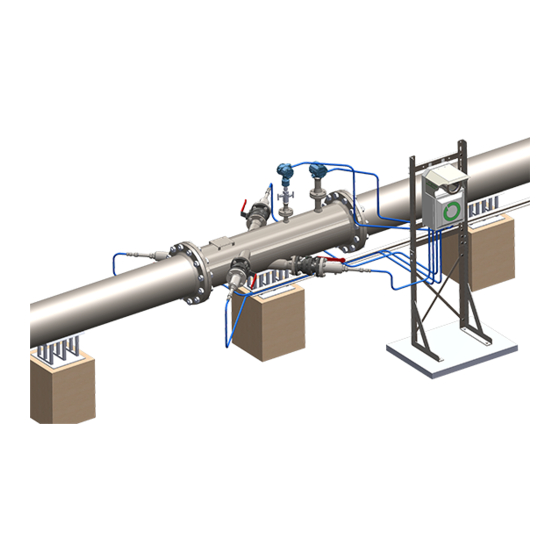
fluenta FGM 160 Installation Instructions Manual
Flare gas meter
Hide thumbs
Also See for FGM 160:
- Maintenance procedures (4 pages) ,
- Operating instructions manual (27 pages) ,
- User manual (34 pages)
Table of Contents
Advertisement
Document number: 62.120.001
Document title:
Scope:
ISO 9001:2008 §7.2.3
Additional Information (when applicable)
F
2016.03.01
Draining plug note added
E
2014.07.14
Updated installation guidelines
D
2013.11.29
Proofread and updated
Removed from User Manual, updated:
C
2013.02.14
changes in content.
B
2009.05.29
Updated information
Issued for Fluenta release; moved to User
A
2007.11.26
Manual
Rev.
Issue date
index
Replacement for:
Fluenta source doc.
(for translations):
FGM 160 Installation and Hook-Up
Instructions
Reason for issue
AH
MW
-
AP
MS
KP
AP
MR
CT
MKJ
KH
-
MS
DIÅ
RT
MS
DIÅ
TM
Author
Review
Review
MB
MW
MB
KP
MB
MW
MW
MW
N/A
AAJ
N/A
AAJ
Review
Approved
by QA
Total pages:
40
Advertisement
Table of Contents

Related Manuals for fluenta FGM 160


Summary of Contents for fluenta FGM 160
- Page 1 2014.07.14 Updated installation guidelines 2013.11.29 Proofread and updated Removed from User Manual, updated: 2013.02.14 changes in content. 2009.05.29 Updated information DIÅ Issued for Fluenta release; moved to User 2007.11.26 DIÅ Manual Rev. Review Issue date Reason for issue Author Review...
-
Page 2: Table Of Contents
6.3 Upgrading from the FGM 130 ....................38 7. References ............................39 8. Appendix I - Space requirements for the TFS ................40 TABLE OF FIGURES Figure 1: Fluenta’s minimum straight up- and downstream distances to disturbances......7 62.120.001 Page 2 of 40... - Page 3 Figure 34: Connection details for ultrasonic transducers..............26 Figure 35: Pressure and temperature transmitter hook-up..............27 Figure 36: FGM 160 – 4-20 mA pressure and temperature transmitter connections......28 Figure 37: Pressure and Temperature HART transmitter connection........... 28 Figure 38: Data and Signal Cables.
-
Page 4: Purpose
Fluenta Flare Gas meter, Field Computer (FGM 160) system. This document provides details on the different options that are available on the FGM 160 system, the installation of the base system, and the optional configurations. The optional configurations include the two types of transducer, possible upgrade from previous Fluenta Flare Gas Meters, and the different interfaces available from the Flow Computer to the Plant Control System. -
Page 5: General
4.2 Ex-Classification Marking Make sure that the FGM 160 is certified for the area and hazardous zone it is intended to be installed in. The Ex-Classification marking of the equipment is described in: FGM 160 – Hazardous Area Installation Guidelines [2]. -
Page 6: Equipment Information
FGM 160 Installation and Hook-Up Instructions 4.3 Equipment Information The FGM 160 requires +24 VDC power supply (nominal). If 24 VDC is not available, an optional 110-230 VAC/24 VDC converter can be supplied by Fluenta. For more detailed equipment information and equipment ratings, please refer to: FGM 160 –... -
Page 7: Space Requirements For The Transducer Full Size, Tfs
FGM 160 Installation and Hook-Up Instructions Figure 1: Fluenta’s minimum straight up- and downstream distances to disturbances. 5.1.1.1 Space Requirements for the Transducer Full Size, TFS There are two different space requirements for the TFS installation. This is due to the fact that for pipes with a diameter of 10”... -
Page 8: Figure 2: Distance Requirements For The Pressure And Temperature Transmitters
FGM 160 Installation and Hook-Up Instructions These transmitters should be mounted on top of pipe if the pipe is horizontality oriented or at a 90° angle to the transducers if the pipe is vertically oriented. These positions are chosen in accordance with best engineering practice. -
Page 9: Mounting The Transducer Holders
FGM 160 Installation and Hook-Up Instructions 5.2 Mounting the Transducer Holders There are three ways to mount the transducer holders. The first is by mounting a Spool piece which is a pre-fabricated pipe with all of the holders (transducer, pressure, and temperature) already mounted. -
Page 10: Vertical Flare Pipe
FGM 160 Installation and Hook-Up Instructions 5.2.1.2 Vertical Flare Pipe The transducer holders may also be mounted on a vertical section of flare pipe. The orientation of the transducer holders in this case does not matter, as the possibility of fluid filling the upstream transducer holder is the same regardless of the orientation. -
Page 11: Cold Tapping
5.2.2 Cold Tapping Installation of transducer holders must always be supervised by trained Fluenta personnel. Before installing the transducer holders on the pipe, the correct placement of the spot marks must be ensured. There are numerous ways this can be done. -
Page 12: Figure 8: Marking A Line Around The Pipe Using A Marking Band
FGM 160 Installation and Hook-Up Instructions Spot A Figure 8: Marking a line around the pipe using a marking band. Mark the hole for the sensors on the pipe wall following the inside rim of the transducer holder when they are mounted in the welding-jig. Repeat the procedure for the other transducer holder. -
Page 13: Figure 9: Machined Hole
Usually, the welder will use three or four tacks. Ensure that there is enough space to insert the transducer. Fluenta recommends using the sighting tool to verify this. The tool should be able to be inserted without any friction or obstructions. -
Page 14: Figure 12: Welding Jig And Transducer Holder
FGM 160 Installation and Hook-Up Instructions necessary to pay close attention during the welding, regularly checking the angles with the digital electronic level. Figure 12: Welding jig and transducer Figure 13: Transducer holder welded to the pipe. holder. This activity needs to be carried out by a skilled welder as precision and accuracy is necessary to get the transducer holders welded into their right positions. -
Page 15: Using The Sighting Tool
FGM 160 Installation and Hook-Up Instructions 5.2.3 Using the Sighting Tool There are two types of sighting tool, one for each angle set. The first type, shown in Figure 15, is for transducer holders mounted at a 45° angle. There are two tools in a set, one fits tightly in each transducer holder. -
Page 16: Hot Tapping Transducers Full Size, Tfs
FGM 160 Installation and Hook-Up Instructions When using the sighting tool for pipes that are 10” and less, use the measurement from the special tool as described in section 5.3.1 to find the correct depth for the transducer. This depth should be the same for the sighting tool. Measure from the narrow end of the sighting tool and tighten the stop washer at that position. -
Page 17: Mounting The Ultrasonic Transducers
Determining the Correct Position for the Transducers Fluenta will use a special gas proof measuring tool to find the correct position for the transducers, as shown in Figure 22. The method is shown in the figure below. This is carried out on site during installation of the transducers due to the fact that the entire length is measured, including ball valves and gaskets. -
Page 18: Edge Flush Transducer Mounting
For the FGM 160, the transducer distance can be found in the O&S Console software under Config – Config Main Page – Mechanical Parameters – Measured (length in m). -
Page 19: 45° Installations
FGM 160 Installation and Hook-Up Instructions Figure 25: Retracted tranducers distance. When the transducers are retracted, the transducer distance will increase from the original distance (red arrow in Figure 25) to the new transducer distance (green arrow). This must be updated in the flow computer. -
Page 20: 48°/42° Installations
FGM 160 Installation and Hook-Up Instructions 5.3.2.3 48°/42° installations For an installation where the transducer-holder angles are 48° (Downstream) and 42° (Upstream), the retraction needed for each transducer is 16.2mm for the 48° transducer (see Figure 27), and 20mm for the 42° transducer (see Figure 28). The transducer distance must then be increased by 36.2mm (16.2mm+20mm) in the flow computer configuration. -
Page 21: Insertion Of The Transducer Full Size (Tfs)
When the transducer holders and ball valves are installed, the ultrasonic transducers may be inserted. This shall ONLY be done by personnel certified by Fluenta. If this is a first time installation, the transducer holder should be checked for liquid and drained prior to installation. -
Page 22: The Field Computer Mounting Frame
Main fuses should not be inserted at any stage of the installation phase All cables should be connected to the terminals in the Ex-e enclosure of the FGM 160. The blue terminals are IS (Intrinsically Safe) and are connected to the field computer through internal IS barriers. -
Page 23: Cable Preparations
FGM 160 Installation and Hook-Up Instructions Figure 31: Ex-e enclosure terminals overview. Note: Foundation Fieldbus terminal overview available in doc. no. 77.120.217. 6.2.1 Cable Preparations The steps described below should be carried out at both ends of the cables. However, the installation of glands is not applicable for the Local Equipment Room. -
Page 24: Power Cable
6.2.2 Power Cable The FGM 160 requires a 24 VDC power supply (ref. section 4.3 Equipment Information). Keep the twisting of the conductor pair and route the conductors to the power input terminals (ref. Figure 31). If applicable, terminate the screen to the PE Earthbar. -
Page 25: Figure 33: Connecting The Ultrasonic Transducers To The Fgm 160
FGM 160 Installation and Hook-Up Instructions Figure 33: Connecting the Ultrasonic Transducers to the FGM 160. 62.120.001 Page 25 of 40... -
Page 26: Figure 34: Connection Details For Ultrasonic Transducers
FGM 160 Installation and Hook-Up Instructions The ultrasonic transducers shall be connected as follows. This is carried out at the Fluenta production facilities. Upstream: Ch1Up–IS Ch1Up+IS Ch1Up_G Downstream: Ch1Dn-IS Ch1Dn+Is Ch1Dn_G Keep the twisting of the conductor pairs when connecting to terminals. -
Page 27: Connecting The Pressure And Temperature Transmitters
Ex-e enclosure, no barriers are required, as these are built-in in the IS Barrier module within the FGM 160. For detailed information regarding the built-in barriers and the optional grounding wire shown in Figure 35, please refer to: FGM 160 – Hazardous Area Installation Guidelines [2]. -
Page 28: Figure 36: Fgm 160 - 4-20 Ma Pressure And Temperature Transmitter Connections
FGM 160 Installation and Hook-Up Instructions Figure 36: FGM 160 – 4-20 mA pressure and temperature transmitter connections. Figure 37: Pressure and Temperature HART transmitter connection. 62.120.001 Page 28 of 40... -
Page 29: Control Room And Data Cables
6.2.5.1 DCS Port, Modbus The FGM 160 can be interfaced to a DCS Modbus system by an RS 485 signal interface. Normally a 2-wire interface is used, but 4-wire interface can also be used. For detailed information regarding the DCS port wiring, please refer to: FGM 160 –... -
Page 30: Service Port
Each of the current loop outputs can be configured either as active or passive output. In active output configuration, the current loop is powered from the FGM 160 field computer. In passive output configuration, an external power source is required. -
Page 31: Figure 40: Active Output Current Loop(S), Wiring
FGM 160 Installation and Hook-Up Instructions 6.2.5.4.1 Active Output Configuration (Default Configuration) In active output configuration, the current loops are powered from FGM 160 computer (30V loop voltage). In active output configuration: - “CLx out” terminal is connected to CL-GND. -
Page 32: Figure 41: Passive Output Current Loop(S), Wiring
FGM 160 Installation and Hook-Up Instructions 6.2.5.4.2 Passive Output Configuration In passive output configuration, the current loops are powered from an external loop power source (5V – 50V, see section 6.2.5.4.4, Load / Loop Voltage Limitations, for more details). In passive output configuration: - Current loop is connected between “CLx in”... -
Page 33: Figure 42: Current Loop Outputs, Details
FGM 160 Installation and Hook-Up Instructions 6.2.5.4.3 Current Loop Outputs Details The current loop outputs of the FGM 160 are galvanic isolated from the rest of the FGM 160 field computer. However, they are not individually isolated with respect to each other (they all share the same ground reference point). -
Page 34: Figure 43: Current Loop Outputs, Load/Voltage Limitations
FGM 160 Installation and Hook-Up Instructions Figure 43: Current loop outputs, Load/Voltage limitations 6.2.5.4.5 Restrictions of the Current Loop Outputs High side load/Low side load The load resistor should normally be connected on high side (see Figure 44 and Figure 45). -
Page 35: Hart Output
FGM 160 Installation and Hook-Up Instructions Figure 46: Multiple current loop outputs, Active output configuration Figure 47: Multiple current loop outputs, Passive output configuration 6.2.5.5 HART Output One of the current loop outputs (CL6) can be configured and used as a HART communication channel. -
Page 36: Pulse/Frequency/Level Output
For detailed information regarding wiring of the HART output channel, please refer to: FGM 160 – HART Output Interface Specification [6]. 6.2.5.6 Pulse/Frequency/Level Output As an option, the FGM 160 can be configured with one passive pulse/frequency/level output. This output can be configured in three different ways: Pulse output configuration. -
Page 37: Figure 48: Fgm 160 Pulse/Frequency Output Connections
Voltage / Current Limitations Maximum voltage: 30V Maximum current: 40 mA (output is protected by a 62mA internal fuse) Figure 48: FGM 160 Pulse/frequency output connections Figure 49: FGM 160 Pulse/frequency output connections. Without external power 62.120.001 Page 37 of 40... -
Page 38: Upgrading From The Fgm 130
FGM 160 Installation and Hook-Up Instructions 6.3 Upgrading from the FGM 130 It is strongly recommended to upgrade all FGM 130 installations to FGM 160. The upgrade is relatively simple and easy to perform. Existing mounts can be used, although the transducers must be replaced, as the FGM 160 uses upgraded Ultrasonic Transducers, and the signal is not backward compatible with the Ultrasonic Transducers used with the FGM 130. -
Page 39: References
Compatible, with an additional HART DCS/SCADA Interface interface REFERENCES FGM 160 – Preservation, Packing, Unpacking and Storage Procedure FGM 160 – Hazardous Area Installation Guidelines FGM 160 – Field Wiring Diagram, Fluenta Doc.no.: 77.120.509 FGM 160 – DCS Modbus Interface Specifications FGM 160 –... -
Page 40: Appendix I - Space Requirements For The Tfs
FGM 160 Installation and Hook-Up Instructions APPENDIX I - SPACE REQUIREMENTS FOR THE Figure 51: Space requirements for the TFS 62.120.001 Page 40 of 40...
Need help?
Do you have a question about the FGM 160 and is the answer not in the manual?
Questions and answers