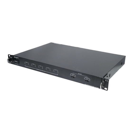
Summary of Contents for Sony WD-880A
- Page 1 3-856-875-21 (1) UHF Antenna Divider Operating Instructions Before operating the unit, please read this manual thoroughly and retain it for future reference. WD-880A 1996 by Sony Corporation...
- Page 2 WARNING VORSICHT Um Feuergefahr und die Gefahr eines To prevent fire or shock hazard, do not elektrischen Schlages zu vermeiden, darf das expose the unit to rain or moisture. Gerät weder Regen noch Feuchtigkeit To avoid electrical shock, do not open the ausgesetzt werden.
-
Page 3: Table Of Contents
Table of Contents Overview ..................... 4 Precautions ....................5 Location and Function of Parts ..............6 Front Panel ..................... 6 Rear Panel ....................7 Connection to the WD-820A ..............8 System Configuration ................9 24-Channel System Plan Using Group U1 or U2 ........9 24-Channel System Diagrams .............. -
Page 4: Overview
Overview The WD-880A is a rack-mountable UHF antenna divider which enables simultaneous operation of up to 24 channels of the 800 MHz band wireless microphone system. Up to 24-channel simultaneous operation By using the WD-880A with the Sony synthesized wireless microphone system, up to 24 channels of simultaneous operation can be available between TV channel 59 and 61 bands. -
Page 5: Precautions
Precautions • The unit must be used within a temperature range of 0°C to +50°C (+32°F to +122°F). To obtain the optimum performance of the unit, use within a range of +15°C to +35°C (+59°F to +95°F) is recommended. Avoid using the unit for extended periods at extremely high temperatures or placing it in direct sunlight, as this may damage the finish of the case. -
Page 6: Location And Function Of Parts
Location and Function of Parts Front Panel 1 POWER indicator DC OUT ANTENNA a ANTENNA b POWER CONNECTION INDICATOR UHF ANTENNA DIVIDER WD-880 3 CONNECTION INDICATORs 5 ANTENNA b DC OUT switch 2 POWER switch 4 ANTENNA a DC OUT switch 1 POWER indicator 4 ANTENNA a DC OUT switch Lights when the unit is turned on. -
Page 7: Rear Panel
Rear Panel 1 ANTENNA a / ANT IN/DC OUT (9V/OFF/12V) connector 2 ANTENNA a / OUTPUT (TV-CH) 59 to 61 connectors 3 AC IN connector ⁄ AC IN DC OUT DC OUT (9V/OFF/12V) (9V/OFF/12V) OUTPUT (TV-CH) OUTPUT (TV-CH) ANT IN ANT IN ANTENNA ANTENNA... -
Page 8: Connection To The Wd-820A
Connection to the WD-820A AN-820A AN-820A WD-880A ⁄ AC IN DC OUT DC OUT (9V/OFF/12V) (9V/OFF/12V) ANT IN OUTPUT (TV-CH) OUTPUT (TV-CH) ANT IN ANTENNA ANTENNA WD-820A WD-820A for TV-CH61 for TV-CH61 WD-820A WD-820A for TV-CH60 for TV-CH60 WD-820A for TV-CH59 ⁄... -
Page 9: System Configuration
System Configuration This section introduces you examples of the 24-channel reception system plan and diagrams using the WD-880A antenna divider. For further details on system configuration and channel plans, refer to the operating instructions of the WRR-850A/840A/820A UHF synthesized diversity tuners. -
Page 10: 24-Channel System Diagrams
The typical system examples according to the system plan using groups U1 or U2 are shown below. When operating 24 channels simultaneously, you will need both the WD- 820A and the WD-880A antenna dividers. Example 1: System with the WRR-850A AN-820A... - Page 11 Example 2: System with the WRR-840A AN-820A AN-820A WD-880A TV-CH59 TV-CH60 TV-CH61 WD-820A WD-820A WD-820A WRR- WRR- WRR- 840A (59) 840A (61) 840A (60) TV Channel 59: 8 Channels TV Channel 61: 8 Channels TV Channel 60: 8 Channels Group U1 or U2...
-
Page 12: Channel Plan And Freqeuncy Assignment For Groups U1 And U2
System Configuration Channel Plan and Freqeuncy Assignment for Groups U1 and U2 Groups U1 and U2 are planned to simultaneously receive up to 8 wireless microphones. Group U1 Frequency (in MHz) TV-CH59 TV-CH60 TV-CH61 Channel Frequency Channel Frequency Channel Frequency 59-11 775.375 60-11... -
Page 13: Rack Mounting
Bottom panel WD-880A Mount the unit on the rack using screws that are at least 10 mm ( in.) long and that match the diameter of the screw holes on the rack. -
Page 14: Removing The Mounting Brackets
Dimensions Unit: mm (inches) Front view 482 (19) 430 (17) DC OUT ANTENNA a ANTENNA b POWER CONNECTION INDICATOR UHF ANTENNA DIVIDER WD-880 Rack mounting bracket WD-880A Rack mounting bracket Side view 300 (11 Rack mounting bracket... -
Page 15: Specifications
Specifications Frequency range 774 to 798 MHz Antenna input connectors BNC-R type (1 each for antennas “a” and “b”) Antenna output connectors BNC-R type (3 each for antennas “a” and “b”) Antenna input/output impedance 50 ohms Number of RF distribution 3 distributions (TV channels 59 to 61) each for antennas “a”... - Page 16 Sony Corporation Printed in Japan...


Need help?
Do you have a question about the WD-880A and is the answer not in the manual?
Questions and answers