Table of Contents
Advertisement
Quick Links
Advertisement
Table of Contents

Related Manuals for Sony AN-LP1


Summary of Contents for Sony AN-LP1
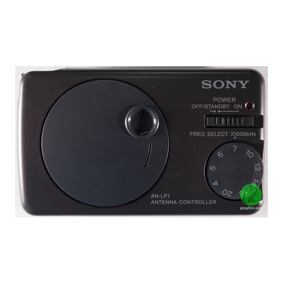
- Page 1 AN-LP1 SERVICE MANUAL US Model Canadian Model AEP Model UK Model E Model Australian Model Tourist Model • This set consists of the following units. Antenna Module Antenna Controller Filter Unit SPECIFICATIONS SHORT WAVE ACTIVE ANTENNA MICROFILM...
-
Page 2: Section 1 General
SECTION 1 This section is extracted from instruction manual. GENERAL – 2 –... -
Page 4: Section 2 Disassembly
SECTION 2 DISASSEMBLY Note: Follow the disassembly procedure in the numerical order given. CABINET (FRONT/REAR), REEL ASS’Y 3 step tapping screw (2) 2 two screws (M1.7) 4 cabinet (rear) 2 two screws (M1.7) 4 cabinet (front) 5 reel ass’y 1 battery case lid NOTE FOR INSTALLATION •... - Page 5 CONTROL/REEL BOARD 1 Remove six solders of cord (WITH PLUG) and 3 reel board reel board. 1 Remove two solders of battery terminal (+) and battery spring (–) reel board 2 control board surface of contacts Note on instalation: Apply grease (J-2502-028-1) to the surface of contacts on the reel board.
-
Page 6: Frequency Adjustment
SECTION 3 ELECTRICAL ADJUSTMENT FREQUENCY ADJUSTMENT Adjustment and Connection Location: Connection: [ANTENNA BOARD] (Conductor Side) Note: Make this adjustment, if either ANTENNA board or CONTROL board in this set was replaced or if equivalent work was executed, because these boards have been adjusted in a pair. 1. - Page 7 AN-LP1 SECTION 4 DIAGRAMS 4-1. PRINTED WIRING BOARDS • Semiconductor Location Ref. No. Location D101 D102 D103 B-10 D104 D105 D106 D107 D108 IC101 B-10 Q101 Q102 Q103 Q104 Q105 C-10 Q106 Q107 Q108 Q109 Q110 Q111 Q112 Q113 C-10...
- Page 8 AN-LP1 4-2. SCHEMATIC DIAGRAM • Waveforms 1 Q101 BASE 0.5 Vp-p 550 ns 2 Q102 BASE 0.1 Vp-p 550 ns 3 D101 ANODE 34.4 Vp-p 710 ns Note on Schematic Diagram: • All capacitors are in µF unless otherwise noted. pF: µµF 50 WV or less are not indicated except for electrolytics and tantalums.
-
Page 9: Section 5 Exploded Views
SECTION 5 EXPLODED VIEWS NOTE: • -XX and -X mean standardized parts, so they • Items marked “*” are not stocked since they may have some difference from the original one. are seldom required for routine service. Some • Color Indication of Appearance Parts delay should be anticipated when ordering these Example: items. - Page 10 (2) ANTENNA CONTROLLER not supplied Ref. No. Part No. Description Remark Ref. No. Part No. Description Remark A-3638-504-A REEL ASSY 3-907-745-01 SPRING (–), BATTERY 3-015-951-01 KNOB (POWER) 3-363-895-01 SCREW (M1.7) 3-015-948-01 CABINET (FRONT) 3-907-747-01 SPRING (+/–. B), BATTERY 3-899-829-01 WASHER (SLIT) 3-895-517-11 SCREW (2), TAPPING, STEP * 55 A-3679-910-A CONTROL BOARD, COMPLETE...
-
Page 11: Filter Unit
(3) FILTER UNIT not suppled not suppled Ref. No. Part No. Description Remark Ref. No. Part No. Description Remark A-3638-531-A FILTER ASSY, CLAMP 3-309-597-31 SCREW (1.4), TAPPING, PRECISION 1-569-215-11 JACK 1-782-542-21 CORD (WITH PLUG) (2PIN) 1-573-996-11 JACK, SMALL (WATERPROOF) 1-543-798-11 FILTER, CLAMP (FERRITE CORE) –... -
Page 12: Electrical Parts List
SECTION 6 ANTENNA CONTROL ELECTRICAL PARTS LIST NOTE: • Due to standardization, replacements in the • Items marked “*” are not stocked since they When indicating parts by reference parts list may be different from the parts speci- are seldom required for routine service. number, please include the board. -
Page 13: Accessories And Packing Materials
CONTROL Ref. No. Part No. Description Remark Ref. No. Part No. Description Remark D106 8-719-988-62 DIODE 1SS355 R111 1-216-847-11 METAL CHIP 150K 1/16W D107 8-719-988-62 DIODE 1SS355 R112 1-216-841-11 METAL CHIP 1/16W D108 8-719-988-62 DIODE 1SS355 R113 1-216-837-11 METAL CHIP 1/16W R114 1-216-847-11 METAL CHIP...
Need help?
Do you have a question about the AN-LP1 and is the answer not in the manual?
Questions and answers