Table of Contents
Advertisement
These instructions are intended for use only by experienced, qualified combustion start-
up personnel. Adjustment of this equipment by unqualified personnel can result in fire,
explosion, severe personal injury or even death.
To make changes to the burner or adjust firing inputs: 1. Shut the burner down; 2. Make
changes; 3. Restart the burner. STAND CLEAR OF THE BURNER UNDER ANY
FIRING CONDITIONS.
TABLE OF CONTENTS
Subject
General Information..............................................................................
Receiving & Inspection..........................................................................
Burner Capacities.................................................................................
Dimensions.........................................................................................
Component Identification.......................................................................
Combustion Flighting............................................................................
Burner Mounting..................................................................................
Fuel Manifold Installation........................................................................
I.
Natural Gas Fuel Piping System..............................................................
Light Fuel Oil Piping System...................................................................
Heavy Fuel Oil Piping System.................................................................
Oil Manifold Heat Tracing.......................................................................
Heavy Oil Insert Heater.........................................................................
Fuel Oil Nozzle....................................................................................
Compressed Air/Oil Atomizer..................................................................
Liquid Propane (LP) Fuel Piping System...................................................
Liquid Propane (LP) Nozzle....................................................................
Burner Pilot System..............................................................................
Primary Air..........................................................................................
Burner Setup.......................................................................................
Operation...........................................................................................
V.
Adjustments........................................................................................
Maintenance.......................................................................................
X.
Recommended Spare Parts...................................................................
Appendix: Field Installation Weld-In Type flights, Y7100.............................
These instructions are intended to serve as guidelines covering the installation, operation, and maintenance of Hauck equipment. While
every attempt has been made to ensure completeness, unforeseen or unspecified applications, details, and variations may preclude
covering every possible contingency. WARNING: TO PREVENT THE POSSIBILITY OF SERIOUS BODILY INJURY, DO NOT USE OR
OPERATE ANY EQUIPMENT OR COMPONENT WITH ANY PARTS REMOVED OR ANY PARTS NOT APPROVED BY THE
MANUFACTURER. Should further information be required or desired or should particular problems arise which are not covered
sufficiently for the purchaser's purpose, contact Hauck Mfg. Co.
HAUCK MANUFACTURING CO., 100 North Harris Street Cleona, PA 17042 717-272-3051
1/15
MEGASTAR
MS-50 - MS-150
Required Reference: Appropriate Burner Data Sheet
GJ73 Dryer Drum Gas Analysis
GJ75 MegaStar Application Sheet
www.hauckburner.com
TM
BURNER
WARNING
Fax: 717-273-9882
INSTRUCTIONS
Page
2
2
3
5
6
7
7
8
9
13
15
18
18
20
21
26
31
33
34
34
35
36
37
38
39
MS-9
Advertisement
Table of Contents

Subscribe to Our Youtube Channel
Related Manuals for Hauck MegaStar MS-50


Summary of Contents for Hauck MegaStar MS-50
-
Page 1: Table Of Contents
GJ73 Dryer Drum Gas Analysis GJ75 MegaStar Application Sheet These instructions are intended to serve as guidelines covering the installation, operation, and maintenance of Hauck equipment. While every attempt has been made to ensure completeness, unforeseen or unspecified applications, details, and variations may preclude covering every possible contingency. -
Page 2: General Information
WARNING This equipment is potentially dangerous with the possibility of serious personal injury and property damage. Hauck Manufacturing Company recommends the use of flame supervisory equipment and fuel safety shutoff valves. Furthermore, Hauck urges rigid adherence to National Fire Protection Association (NFPA) standards and insurance underwriter’s requirements. -
Page 3: Burner Capacities
Page 3 MS-9 C. BURNER CAPACITIES MEGASTAR BURNER MODEL GAS SPECIFICATIONS (MMBTU/hr) Capacity (MW) 14.7 24.2 29.3 39.6 45.2 (scfh) 636,600 1,050,000 1,270,000 1,720,000 1,960,000 Main Air Flow 17,100 28,100 34,000 46,100 52,500 /hr) (in.w.c.) 14.3 12.6 15.3 13.8 14.5 Main Air Pressure (mbar) 35.6... - Page 4 Page 4 MS-9 C. BURNER CAPACITIES (Continued) MEGASTAR BURNER MODEL LIQUID PROPANE SPECIFICATIONS (MMBTU/hr) Capacity (MW) 21.7 26.4 34.6 39.3 (scfh) 980,000 1,200,000 1,590,000 1,810,000 Main Air Flow 26,300 32,100 42,600 48,500 /hr) (in.w.c.) 12.8 18.5 15.0 18.3 Main Air Pressure (mbar) 31.8 46.0...
-
Page 5: Dimensions
8. Low pressure atomizing air, used for firing low pressure fuel oil or LP, is provided by a 36 osi (155 mbar) Hauck high efficiency Turbo Blower. The low pressure air is used to not only atomize liquid fuels, but also improve mixing speed in the combustion zone. -
Page 6: Component Identification
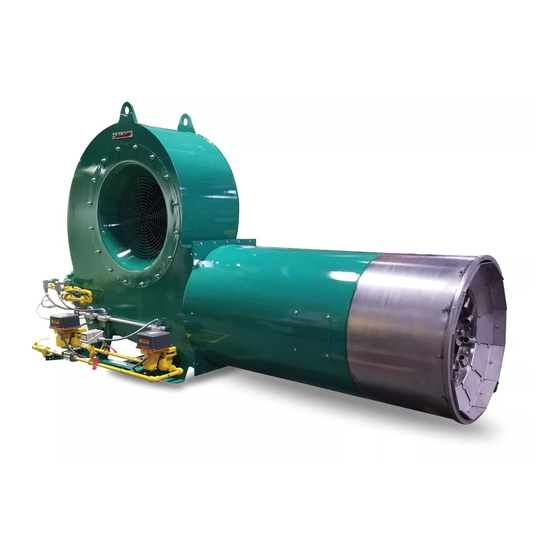
Page 6 MS-9 E. COMPONENT IDENTIFICATION Figure 1. MegaStar Burner Components... -
Page 7: Combustion Flighting
Combustion flights should also have a means of dissipating heat to prevent their destruction by the flame. This is typically done by plowing material over the fights and keeping the flights as low as possible to the drum. Consult Hauck for details on flight design and combustion zone requirements. -
Page 8: Fuel Manifold Installation
(120°C). Oil viscosity should be checked prior to burner operation. Hauck recommends the use of schedule 40 iron pipe and fittings rated for 150 psig (10.3 bar) for natural gas and oil system interconnecting piping. LP applications require the use of schedule 80... -
Page 9: Natural Gas Fuel Piping System
MS-9 I. NATURAL GAS FUEL PIPING SYSTEM NOTE Hauck recommends the use of gas manifolds that meet NFPA guidelines. NFPA requires two fuel safety shutoff valves wired in series and a shutoff valve downstream of the second (blocking) safety shutoff valve, and high and low pressure switches that are interlocked with the burner's safety shutoff valves. - Page 10 Page 10 MS-9 4. Connect the main gas line (see Figure 2). A flexible pipe nipple should be used to connect the gas line to the burner gas manifold (see Table 5 for sizes). IMPORTANT Install a flexible fitting between the gas manifold and the burner gas connection to reduce vibration stress on the manifold.
- Page 11 Page 11 MS-9 GL86 Figure 3. Simplified Gas and Air Flow Chart (@ Atmospheric Conditions)
- Page 12 Page 12 MS-9 Figure 4. MegaStar™ Gas Orifice Meters Graph...
-
Page 13: Light Fuel Oil Piping System
NFPA requirements. 1. Hauck recommends using a flexible connection to connect the oil line to the oil manifold on the burner. A flexible connection will reduce vibration stress on the oil manifold. Refer to Table 7 for recommended flex connection. - Page 14 Page 14 MS-9 MegaStar™ Nominal Oil Pressure Nominal Oil Pressure Model No. w/Low Pressure Atomizer w/Compressed Air Atomizer 75 psig (5.15 bar) 90 psig (6.20 bar) 75 psig (5.15 bar) 90 psig (6.20 bar) 85 psig (5.85 bar) 100 psig (6.90 bar) 65 psig (4.50 bar) 90 psig (6.20 bar) 80 psig (5.50 bar)
-
Page 15: Heavy Fuel Oil Piping System
Page 15 MS-9 X7864 (NOT TO SCALE) Figure 5. Typical Schematic of Burner Light Fuel Oil Piping K. HEAVY FUEL OIL PIPING SYSTEM WARNING Adjustment of this equipment and its components by unqualified personnel can result in fire, explosion, severe personal injury, or even death. - Page 16 2. Heavy fuel oil must be 90 SSU (1.8 x 10 /sec) or less for proper atomization and burning. Use a Hauck viscometer kit (order separately - Part No. 36931) to determine proper oil temperature to achieve this viscosity. Refer to the instructions that are supplied with the kit for proper use.
- Page 17 Page 17 MS-9 NOTE Fuel oil flow settings per the individual burner performance sheets are for initial set-up only. Final settings may have to be readjusted for required operation. 8. Fuel oil flow rates can be checked with the in-line oil flow meter on the burner fuel oil manifold.
-
Page 18: Oil Manifold Heat Tracing
(see Figure 7). The Hauck heat tracing kit installed on the heavy oil manifold will aid in viscosity control and reliable main flame ignition of the burner. The oil manifold heat tracing kit consists of heat tracing cable which is wrapped around all piping, and covered with fiberglass insulation and jacketing. - Page 19 Page 19 MS-9 V7867 (NOT TO SCALE) Figure 8. Heavy Oil Insert Heater NOTE 120V/60Hz power for the heavy oil insert heater must be supplied separately by the customer and wired into the heater junction box. Operation of the heavy oil insert kit is as follows (see Figure 8): 1.
-
Page 20: Fuel Oil Nozzle
Page 20 MS-9 N. FUEL OIL NOZZLE The position of the fuel oil atomizer affects its ability to atomize the oil. The compressed air atomizer or low pressure atomizer should be positioned as shown in Figure 9. CAUTION Ensure that the correct atomizer W7868 is being used when firing oil. -
Page 21: Compressed Air/Oil Atomizer
O. COMPRESSED AIR/OIL ATOMIZER The Hauck high pressure oil nozzle is designed to finely atomize No. 2 fuel oil and clean preheated No. 4, No. 5 and No. 6 fuel oil. Oil viscosity should be 90 SSU (1.8 x 10 /sec) or less. - Page 22 Page 22 MS-9 Compressed Oil Pressure Air Pressure MegaStar To Burner Compressed To Burner Model No. Oil Flow Nozzle Air Flow Nozzle (gpm) (lpm) (psig) (kPa) (scfm) /min) (psig) (kPa) 45.4 75/100 34.1 22.7 1.25 68.1 125/150 37.9 18.9 11.4 Table 11.
- Page 23 Page 23 MS-9 IMPORTANT For all heavy fuel oil applications, i.e., any oil requiring heating for use, oil piping must be heat traced (electric or steam) and insulated. Self-regulating heat tracing is recommended to maintain the desired temperature of a given fuel oil to achieve 90 SSU (1.8 x 10 /sec) or less at the burner.
- Page 24 Page 24 MS-9 W7084 (NOT TO SCALE) Figure 11. Primary Air Tube Pipe Plug Location COMPRESSED AIR FLOW METER The compressed air flow meter is offered with a standard multi-pressure flow scale. The multi-pressure flow scale has a vertically graduated scale, calibrated for air in standard cubic feet per minute (scfm) at 1.0 s.g.
- Page 25 Page 25 MS-9 Figure 12. Compressed Air Flow Meter and Scale To change the compressed air/oil nozzle position. 1. Ensure that the burner is not firing, then close the manual oil valve and the manual compressed air ball valve at the burner. The burner must not be firing 2.
-
Page 26: Liquid Propane (Lp) Fuel Piping System
1. LP or butane is supplied to the MegaStar™ burner in a liquid form and is vaporized as the fuel exits the burner nozzles. 2. Hauck recommends using a flexible connection to connect the LP line to the burner. A flexible connection will reduce vibration stress on the LP connection. Refer to Table 12 for recommended flex connection. - Page 27 40 F, consult Hauck for recommendations. CAUTION Hauck strongly recommends that a bypass flow control valve and a backpressure regulator be installed in all LP systems and piped as shown in Figure 13. 6. After completing piping, check all LP lines and connections for leaks following accepted...
- Page 28 Page 28 MS-9 WARNING Frost or icing is an indication of an LP leak. It is possible for a leak to occur without such evidence. Although the LP supply is initially in a liquid state, as it is vaporized it becomes heavier than air and accumulates near the ground and dissipates relatively slowly, becoming highly flammable.
- Page 29 9. Different size nozzle holes are required on propane, butane, or mixtures of both to assure optimum vaporization and combustion. If using a butane or propane / butane mixture, be sure to specify the fuel when ordering and consult Hauck for specific nozzle hole sizes. 10. The MegaStar utilizes a multi-port LP nozzle assembly positioned around the primary air tube.
- Page 30 Page 30 MS-9 Figure 14. Vapor Pressures of Propane, Butane and Butane-Propane Mixtures...
-
Page 31: Liquid Propane (Lp) Nozzle
Page 31 MS-9 Q. LIQUID PROPANE (LP) NOZZLE To install the liquid propane (LP) nozzle, it is necessary to work on both the front and rear of the burner. All necessary safety procedures should be followed to ensure that work can be performed on both ends of the burner. - Page 32 Page 32 MS-9 W9048 (NOT TO SCALE) Figure 16. Burner Front End W9048 (NOT TO SCALE) Figure 17. LP Insert...
-
Page 33: Burner Pilot System
25 ft (7.6m), use 1/2 NPT (DN 15) or larger piping. Constant gas pressures ranging from 15 psig (1.03 bar) minimum to 25 psig (1.72 bar) maximum must be available at the inlet of the Hauck gas pilot manifold. Pilot capacity should not exceed 150,000 Btu/hr (44kW). -
Page 34: Primary Air
Primary air is used for improved mixing at low fire on LP fuel, and for the optional low pressure atomization of oil fuel. Hauck offers a TBA blower for primary air supply. The primary air blower is supplied with an outlet flange to mate to the air connection on the burner. Piping between the blower and the burner is not supplied with the burner. -
Page 35: Operation
Page 35 MS-9 5. Propane Metering Valve. Low fire is adjusted at the main LP fuel valve. Adjust while watching the LP fuel flow meter. If freezing occurs, open the low fire setting ¼ of a position at a time until the freezing stops. The valve travel varies for a given burner model (see individual burner capacity and performance data sheets). -
Page 36: Adjustments
Page 36 MS-9 2. The combustion air must cycle to 60 Hz for purging the system before light off, the safety limits must be satisfied, and the purge air pressure switch must be made for the purge to begin. The plant exhaust fan must be running with its damper open sufficiently for the proper purge time. -
Page 37: Maintenance
5. A yearly check of the fan (impeller/motor) vibration, measured in the vertical direction at the motor bearings, is recommended. Consult Hauck for acceptable vibration levels. 6. MegaStar fan impellers are equipped with wear resistant impeller blades. However, every effort should be made to minimize dust entering into the fan impeller. -
Page 38: Recommended Spare Parts
Page 38 MS-9 8. Periodically check air/fuel ratio to ensure that the burner is operating at peak efficiency. Exhaust gas analysis can be performed with most commercially available gas analyzers. Y7871 (NOT TO SCALE) Figure 20. Proper Impeller Position On Motor Shaft X. -
Page 39: Appendix: Field Installation Weld-In Type Flights, Y7100
Page 39 MS-9 APPENDIX:... - Page 40 Page 40 MS-9 APPENDIX:...
- Page 41 Page 41 MS-9 APPENDIX:...
- Page 42 Page 42 MS-9 APPENDIX:...
- Page 43 Page 43 MS-9 APPENDIX:...
- Page 44 Page 44 MS-9 APPENDIX:...
- Page 45 Page 45 MS-9 APPENDIX:...
- Page 46 Page 46 MS-9 APPENDIX:...
- Page 47 1/4 inch (6.4 mm) I.D. rubber, plastic, or silicone. 6. Gases should be sampled until instrument settles out, normally a few minutes depending on sample line size, length, and pump volume. HAUCK MANUFACTURING CO., P.O. Box 90 Lebanon, PA 17042-0090 717-272-3051 GJ73FE www.hauckburner.com...
- Page 48 Page 2 GJ73FE Interpretation of Gas Readings. EXAMPLE Assuming a drum gas analysis is taken at production rates. Readings Taken: O - 4% CO - 2000 PPM Combustibles - 2% Problem: 4% O - is too low - is too high Combustibles are too high Solution: Gradually reduce fuel flow or increase air flow while watching O , CO, and...
- Page 49 Page 3 GJ73FE...
- Page 50 Page 4 GJ73FE...
- Page 51 (6 ft or less). Hauck does not recommend carrying material. The dam installed in front of each set of combustion zone flights have a 4 inch opening between the dam sections.
- Page 52 3000°F flame, the recommended combustion flighting works well. Combustion Zone Sizing The following example demonstrates how to calculate the necessary combustion zone length. (Hauck’s e-Solutions for Combustion® Asphalt Heat Balance program is also available). 1. Determine the maximum Btu/hr from the burner capacity sheet necessary; assume burner capacity of 100,000,000 Btu/hr for this example.
- Page 53 Do not be concerned when removing several more feet of veiling flighting to complete the combustion flighting as the new combustion flights will allow extra material heating and drying from conductive heat transfer. Veiling flights can be added to make up the difference in the balance of the drum (Consult Hauck).
- Page 54 Page GJ75FJ For example, consider an ESII-100 firing natural gas at 100 MMbtu/hr in an 8 ft diameter drum. First, use 250,000 Btu/ft as the combustion intensity and then check to see if the flame fits into the available combustion zone. This is a 9 ft long x 5 ft diameter flame @ 30° spin in an 8 ft.
- Page 55 Page GJ75FJ Please Note The Following Important Considerations: Flight spacing of 1/4 inch between flights is important in keeping the combustion zone drum shell temperatures to a minimum. The drum shell should not be exposed directly to the flame. If the drum is exposed, as in the case of uneven flight spacing or missing flights the drum shell temperature in that area could run over 600F.
- Page 56 1. Altitude limitation for 36 osi blower is 2500 ft for heavy oil and 4500 ft for light fuel oil. Above these altitudes, use blower altitude kit or compressed air atomization; consult Hauck. For ES25 and ES50, the blower altitude kit is the only available option for high altitude installations.
Need help?
Do you have a question about the MegaStar MS-50 and is the answer not in the manual?
Questions and answers