
Related Manuals for Delta RMC200


Summary of Contents for Delta RMC200
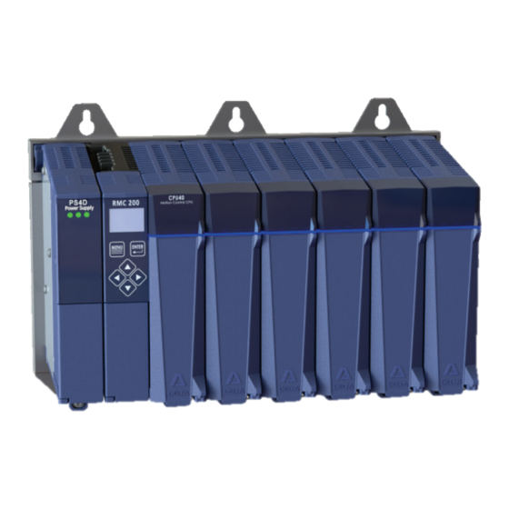
- Page 1 RMC200 MOTION CONTROLLER STARTUP GUIDE With wiring diagrams Connect. Control. Optimize.
- Page 2 Where to Get Help Where to Get Help Video Tutorials In RMCTools, on the Help menu, click Video Tutorials. RMCTools Help In RMCTools, on the Help menu, click Help Topics. Forum forum.deltamotion.com Delta Technical Support Phone: +1-360-254-8688 Email: support@deltamotion.com deltamotion.com...
- Page 3 • modules. Maintenance: The RMC200 contains no user-serviceable parts. The RMC200 should be repaired only by personnel authorized by Delta. Notices used in this document: WARNING: Identifies information about circumstances that can lead to personal injury or death, property damage, or economic loss.
- Page 4 Important Information Important Information WARNING: Using this product in a manner not specified by the manufacturer may impair the protection provided by the equipment. WARNING: Employ safety circuits or devices external to the motion controller to ensure the machine operates safely even in the event of a failure in any part of the controller.
-
Page 5: Table Of Contents
Continuing the Motion Application ........ 28 Diagnostic Tools ............31 Appendix A: Wiring ............32 Appendix B: Mounting Dimensions ....... 51 Appendix C: Agency Compliance ......... 53 Version 1.04, March 7, 2019 Copyright © 2019, Delta Computer Systems, Inc. deltamotion.com... -
Page 6: Step 1: Mount The Base
The environment must conform to the following: Operating ambient temperature -4 to +140°F (-20 to +60°C) Storage ambient temperature -40 to +185°F (-40 to +85°C) Ambient humidity 5-95%, non-condensing Keep liquids and conductive particles away from the RMC200. Delta Computer Systems, Inc. - Page 7 Step 1: Mount the Base Enclosure If the RMC200 is installed in an electronics enclosure, the enclosure must be large enough to dissipate the power that is being generated by the components in the cabinet without having the air temperature in the cabinet exceed the rating on any of the components within the cabinet.
-
Page 8: Step 2: Mount The Modules
RMC200 Startup Guide Step 2: Mount the Modules Module Locations Modules may only be installed in compatible slots on the base. Modules are keyed so only compatible modules mount in a given slot. Slot Compatible Modules PS4D (B5, B7 and B11) -
Page 9: Step 3: Wiring
Step 3: Wiring Step 3: Wiring Wire the power, actuators and feedback devices to the RMC according to the instructions in Appendix A: Wiring on page 32. IMPORTANT: Remove external power from the device before wiring. Failure to do so may cause component failure. Wiring Topic Page General Wiring Information... -
Page 10: Step 4: Install Rmctools
Step 4: Install RMCTools Download 1. Go to http://www.deltamotion.com/dloads/ 2. Choose the RMC200 section, then choose the Software section. 3. Choose RMCTools, 32-bit or 64-bit, as required for your computer. RMCTools supports the RMC70, RMC150 and RMC200 controllers. 4. Run the rmctoolsinstall32.exe or rmctoolsinstall64.exe file and follow the instructions. -
Page 11: Step 5: Connect Rmc To Pc
PC peripherals such as printers, and is available at any store that sells electronics. Or, use Ethernet Cable Connect an Ethernet cable to the RMC200 and the PC or Ethernet switch. The RMC200 supports both straight through and crossover cables. -
Page 12: Step 6: Start A New Project
RMC200 Startup Guide Step 6: Start a New Project 1. Start RMCTools. In the Startup dialog, choose Create a New Project and click OK. 2. Enter the Project Name, then click Finish. 3. In the New Controller Wizard, choose Automatically Detect the Controller Information, then click Next. - Page 13 4. Communication Method: Via USB: A. Choose USB and click Next. B. The RMC200 will appear in the list as R200-CPU40. Choose the RMC and click Next. Tip: If multiple controllers are listed, use the serial number to identify your RMC in the list (Device ID). The serial number is accessible on the RMC200 display screen: 1.
- Page 14 Via Ethernet: A. Choose Ethernet and click Next. B. The RMC200 will appear in the list as R200-CPU40. Click the RMC and click Next. Tip: If multiple controllers are listed, use the MAC address to identify your RMC in the list. The MAC address is accessible on the RMC200 display screen: 1.
- Page 15 Step 6: Start a New Project b. Choose Use the following IP address, set the IP Address and Subnet Mask, then click OK. Tip: For help on IP addressing, in the RMCTools help, in the Index tab, type IP Address and choose that item from the list. D.
- Page 16 RMC200 Startup Guide Saving Settings Throughout the startup procedure, make sure to save the configuration changes you make or they may be lost! 1. Save RMCTools Project On the File menu, click Save. 2. Update Flash On the Controller menu, click Update Flash.
-
Page 17: Step 7: Define The Axes
Step 7: Define the Axes Step 7: Define the Axes To use a physical input or output, it must be assigned to an internal software axis. The RMC starts with default axis assignments which you will likely need to change. Make sure to define the axes at the start of the project. - Page 18 RMC200 Startup Guide View Axis Definitions 1. In the Project tree, expand the Axes folder and double-click Axis Definitions. 2. The Axis Definitions dialog opens: The list displays the software axes. To see the assigned hardware, click an axis in the list.
-
Page 19: Step 8: Test Each Actuator
Step 8: Test each Actuator Step 8: Test each Actuator You will now test an actuator such as a hydraulic valve or a motor. You will use the Direct Output command to send a command signal to the actuator. The actuator must already have been wired to the RMC. Set the Output Type 1. - Page 20 RMC200 Startup Guide Enable the Axis – Enable Controller (7) Command 5. In the Command Tool, in the axis the actuator is connected to, click button. 6. Browse to General Commands, click Enable Controller, then click OK. The Enable Controller command enables all the axes to motion commands can be sent to them.
- Page 21 Step 8: Test each Actuator Move the Axis - Direct Output (9) Command WARNING: Use the Direct Output (9) command with caution. It disables the Autostop features of the axis. Fault Controller Button In the next steps, if you need to quickly stop the axis, click the Fault Controller button on the toolbar, or press Ctrl + K on the keyboard.
- Page 22 RMC200 Startup Guide 10. In the Command Tool, click Send. The axis should move, and the Control Output (in the Axis Status Registers) should be 10.0. 11. If the axis did not move, resend the command with a larger Output until the axis moves.
-
Page 23: Step 9: Test Each Feedback Device
Step 9: Test each Feedback Device Step 9: Test each Feedback Device Now that you have connected and tested an actuator, you will verify a feedback device. The device must already have been wired to the RMC. Configure Feedback In Axis Tools, in the Axis Parameters pane, on the Setup tab, you will configure certain parameters depending on the type of input you are using. - Page 24 RMC200 Startup Guide SSI Feedback 1. In the Axis Parameters pane, on the Setup tab, set the Feedback Type to SSI. 2. Set the following parameters: SSI Format • • SSI Data bits (e.g. 24) Linear/Rotary • Choose Format and Data Bits per the SSI device data sheet.
- Page 25 Step 9: Test each Feedback Device Analog Feedback 1. In the Axis Parameters, on the Setup tab, set the Analog Input Type to Voltage (±10V) or Current (4-20mA). If the input is the primary input of the axis, the Input Type is under the Primary Control Setup section in the Axis Parameters.
- Page 26 RMC200 Startup Guide Verify Feedback 1. In the Axis Status Registers pane, on the All tab, expand the Feedback section. For secondary inputs, expand the Pressure/Force/Accel Feedback section. 2. Depending on your feedback type, look at the Counts, Volts or Current register.
-
Page 27: Step 10: Scale And Offset
Step 10: Scale and Offset Step 10: Scale and Offset The Scale and Offset parameters convert the Counts, Volts or Current from the transducer into meaningful measurement units. First, determine the approximate positions at either end of travel. This will help you verify later that you performed the procedure correctly. To set the Scale and Offset: 1. -
Page 28: Step 11: Set The Output Polarity
RMC200 Startup Guide Step 11: Set the Output Polarity The Actual Position, Pressure, Force or Velocity must increase when the RMC applies a positive Control Output percentage. If this condition is not met, you will not be able to perform closed-loop control. -
Page 29: Step 12: Tuning
Step 12: Tuning Step 12: Tuning In order to control an axis in closed-loop, it must first be tuned. You can use autotuning or manually tune the axis. Autotuning – Position Axes Only Autotuning can be used for most position control axes. 1. - Page 30 RMC200 Startup Guide 5. When the wizard is complete, the Gain Calculator will open. Use the slider bar to choose gains. Begin by pulling the slider close to the bottom, then click Apply Gains. 6. Use the buttons you previously set up to move the axis back and forth.
- Page 31 Step 12: Tuning Manual Tuning–Position, Pressure, or Force Axes You can manually tune systems for which autotuning does not work. For instructions: 1. On the help menu, choose Help Topics. 2. On the Index tab, type tuning and double-click about. 3.
-
Page 32: Continuing The Motion Application
A User Program runs on a task. Each task can run one user program at a time. The RMC200 has up to 32 tasks. Therefore, an RMC200 controller may run up to 32 User Programs simultaneously. - Page 33 Most PLCs or other host controllers can communicate with the RMC, which includes reading status, writing values, and sending commands to the RMC. The RMC200 supports a number of Ethernet protocols. WARNING: When the motion controller is remotely controlled by some other device, such as a PLC, make sure to design proper safety interlocks to ensure safe machine operation in the event of communications loss.
- Page 34 RMC200 Startup Guide Program Triggers Use the Program Triggers to start User Programs based on conditions defined by the user. For example, • Start a User Program by writing to an RMC variable from a PLC. Start a User Program when a discrete input turns on.
-
Page 35: Diagnostic Tools
Diagnostic Tools Diagnostic Tools This section describes the main diagnostic tools of RMCTools that will aid you in monitoring and troubleshooting your system. Plots The RMC provides very flexible plotting capabilities. Virtually any register in the RMC can be plotted, and multiple registers may be plotted simultaneously. -
Page 36: Appendix A: Wiring
Quadrature Encoder Analog ±10V, 4-20 mA Quadrature Encoder D24: Discrete I/O WARNING: Miswiring may cause damage to the RMC200 and connected components. WARNING: Pay special attention to wiring the Common pins, or the RMC may not properly receive signals from connected transducers. - Page 37 Use separate power supplies for sensors and actuators. • Unpluggable Terminal Blocks All RMC200 modules employ unpluggable terminal blocks. Features of these terminal blocks include: Latching type to prevent unintended extraction • Spring-cage connectors for consistent wire clamp force •...
- Page 38 RMC200 Startup Guide Wire Gauge, Stripping Length and Ferrule Length IMPORTANT: Use copper wire only. PS4D, PS6D CPU40, CA4, CV8, S8, A8, Q4, D24 Wire gauge, stranded 24 – 12 AWG 24 – 16 AWG 0.2 – 2.5 mm 0.2 – 1.5 mm...
- Page 39 Appendix A: Wiring PS4D and PS6D: Power Input Voltage: Recommended 24 Vdc ±15% (20.4 – 27.6 Vdc), 30 V max. Overvoltage shutdown at 36 V. Input Power: PS4D: 42 W max (1.8 A at 24 Vdc) PS6D: 60 W max (2.5 A at 24 Vdc) For a given power draw, the current draw will be greater at a lower input voltage.
- Page 40 RMC200 Startup Guide CPU40, CA4, CV8: Discrete I/O CPU40: 2 discrete inputs, 2 discrete outputs CA4: 4 discrete inputs (Fault), 4 discrete outputs (Enable) CV8: 8 discrete I/O, individually configurable as inputs or outputs The CPU40, CA4, and CV8 discrete inputs and outputs are individually isolated.
- Page 41 Appendix A: Wiring CA4 and CV8: Control Output The CA4 has 4 analog outputs, individually software selectable as 0-10 V, ±10 V, 4-20 mA, or ±20 mA, with unipolar or bipolar operation, or a custom range within the ±10 V or ±20 mA range. The CV8 has 8 analog outputs, individually software selectable as 0-10 V, ±10 V, with unipolar or bipolar operation, or a custom range within the ±10 V.
- Page 42 RMC200 Startup Guide S8: SSI Transducer Wiring For Synchronous Serial Interface (SSI) transducers and encoders. For linear SSI transducers, make sure to choose the synchronized type. Clock + Clk+ Clock - Clk- Data + Dat+ Data - Dat- DC Gnd...
- Page 43 Appendix A: Wiring S8: SSI Manufacturer-Specific Wiring These diagrams provide transducer manufacturer labels and colors. Follow all SSI wiring instructions on page 38. Balluff Micropulse BTL5 or BTL7 with SSI output Styles: Z, W, K, P Yellow + Clk Clk+ Pink - Clk Clk-...
- Page 44 RMC200 Startup Guide S8: Start/Stop or PWM Transducer Wiring For magnetostrictive transducers with Start/Stop or PWM outputs. Interrogate + Int+ Interrogate - Int- Return + Ret+ Return - Ret- DC Gnd Pwr+ Case +Pwr Power Supply Tip: See next page for manufacturer-specific wiring diagrams.
- Page 45 Appendix A: Wiring S8: Start/Stop and PWM Manufacturer-Specific Wiring These diagrams provide transducer manufacturer labels and colors. Follow all MDT wiring instructions on page 40. Balluff Micropulse BTL-5, digital RS-485 output Styles: Z, W, K, E, P, R, AT Yellow Interrogate + Input Int+ Pink...
- Page 46 RMC200 Startup Guide S8: Quadrature Wiring The S8 supports one RS-422 quadrature encoder input, using channels 6 and 7. Notes: • The S8 module interfaces to RS-422 (3.5-5V differential) signals only. Single-ended (TTL) signals are not supported. • The user must supply power to the transducer.
- Page 47 Appendix A: Wiring A8: Analog Voltage Transducer Wiring Voltage Transducer, 4- or 5-Wire Input Connector +Analog Out In+V -Analog Out Signal Common Pwr Common +Pwr To reduce electrical interference: Case • In- and Cmn must be connected, either internally in the transducer or externally as close as possible to the transducer.
- Page 48 RMC200 Startup Guide A8: Potentiometer with Exciter Pin Note: Use the Exciter pin to increase the measurement accuracy of the potentiometer. Input Potentiometer Connector Wiper In+V +10V Exc Case To reduce electrical interference: • The connection of In- to Cmn should be made as close as possible to the transducer.
- Page 49 Appendix A: Wiring A8: Analog Current Wiring 4-20 mA Current Transducer, 2-Wire Input Connector +Analog Out In+mA +Pwr Sensor Input must be Case configured in software for current. The current input +24 VDC impedance is 250 Ω. Power Supply To reduce noise, use shielded twisted-pair Current Transducer, 4-Wire wire.
- Page 50 RMC200 Startup Guide Q4: Quadrature Encoder Wiring Important: Set the AB Input Type and Z Input Type axis parameters in RMCTools to correspond to the physical signal level and type. See the RMCTools help for details. Differential Signal Single-Ended Signal...
- Page 51 Appendix A: Wiring Q4 Home Inputs Set the H Input Type axis parameter in RMCTools to correspond to the type of signal. See the RMCTools help for details. Q4 Registration Inputs Set the R Input Type axis parameter in RMCTools to correspond to the type of signal.
- Page 52 RMC200 Startup Guide D24: Discrete I/O Overview The D24 discrete I/O are organized into 4 sections: DI/O # Features Group A Input or output – nominal 24V. Software-configurable. Each group is Group B 8-15 isolated. Within each group, all inputs...
- Page 53 Appendix A: Wiring D24: Discrete Inputs To turn on a discrete input, apply a voltage of the correct level. The polarity is unimportant for inputs 0-19, and is important for 20-23. Inputs 0-19 Inputs 20-23 Signal Levels 12-24 VDC 5-24 VDC Max Current Draw 3 mA 7 mA...
- Page 54 RMC200 Startup Guide D24: Quadrature Encoder The D24 high-speed inputs 20-23 supports the following quadrature encoder feedback and pulse train signal types: • 5V Differential Differential HTL (High Threshold Logic) for 12V to 24 V • RS-422 • RS-422 will only work in this configuration if the differential output is greater than 3.5V.
-
Page 55: Appendix B: Mounting Dimensions
Appendix B: Mounting Dimensions Appendix B: Mounting Dimensions Clearance The required clearance above and below for airflow Clearance depends on the maximum ambient temperature: Ambient Temperature Clearance 122 - 140°F (50 - 60°C) 3 in. (7.6 cm) Less than 122°F (50°C) 2 in. - Page 56 RMC200 Startup Guide B11: B15: Delta Computer Systems, Inc.
-
Page 57: Appendix C: Agency Compliance
Appendix C: Agency Compliance Appendix C: Agency Compliance The following modules are CE compliant: B7, B11, B15, PS4D, PS6D, CPU40, S8, A8, D24, CA4 For CE compliance and to minimize electrical interference: • Install a ferrite ring on the power wires to the PS4D or PS6D power supply module. - Page 58 RMC200 Startup Guide Notes Delta Computer Systems, Inc.
- Page 59 Appendix C: Agency Compliance Notes deltamotion.com...
- Page 60 RMC200 Startup Guide The RMC Family of Motion Control Connect. Control. Optimize. Delta Computer Systems, Inc.
Need help?
Do you have a question about the RMC200 and is the answer not in the manual?
Questions and answers