
Related Manuals for ASROCK X470D4U


Summary of Contents for ASROCK X470D4U
- Page 1 X470D4U User Manual Version 1.0 Published December 2018 Copyright©2018 ASRock Rack INC. All rights reserved.
- Page 2 (including damages for loss of profits, loss of business, loss of data, interruption of business and the like), even if ASRock Rack has been advised of the possibility of such damages arising from any defect or error in the documentation or product.
- Page 3 Contact Information If you need to contact ASRock Rack or want to know more about ASRock Rack, you’re welcome to visit ASRock Rack’s website at www.ASRockRack.com; or you may contact your dealer for further information. ASRock Rack Incorporation 6F., No.37, Sec. 2, Jhongyang S. Rd., Beitou District,...
-
Page 4: Table Of Contents
Contents Chapter 1 Introduction Package Contents Specifications Unique Features Motherboard Layout Onboard LED Indicators I/O Panel Block Diagram Chapter 2 Installation Screw Holes Pre-installation Precautions Installing the CPU Installing the CPU Fan and Heatsink Installing Memory Modules (DIMM) Expansion Slots (PCI Express Slots) Jumpers Setup Onboard Headers and Connectors Dr. - Page 5 3.1.1 UEFI Menu Bar 3.1.2 Navigation Keys Main Screen Advanced Screen 3.3.1 CPU Configuration 3.3.2 Chipset Configuration 3.3.3 Storage Configuration 3.3.4 ACPI Configuration 3.3.5 USB Configuration 3.3.6 Super IO Configuration 3.3.7 H/W Monitor 3.3.8 AMD CBS 3.3.9 AMD PBS 3.3.10 Instant Flash Server Mgmt 3.4.1 System Event Log 3.4.2 BMC Network Configuration...
- Page 6 Support CD Information 4.2.1 Running The Support CD 4.2.2 Drivers Menu 4.2.3 Utilities Menu 4.2.4 Contact Information Chapter 5 Troubleshooting Troubleshooting Procedures Technical Support Procedures Returning Merchandise for Service...
-
Page 7: Chapter 1 Introduction
In case any modifications of this manual occur, the updated version will be available on ASRock Rack website without further notice. You may find the latest memory and CPU support lists on ASRock Rack website as well. ASRock Rack’s Website: www.ASRockRack.com If you require technical support related to this motherboard, please visit our website for specific information about the model you are using. -
Page 8: Specifications
1.2 Specifications X470D4U MB Physical Status Form Factor micro-ATX Dimension 9.6'' x 9.6'' (24.4 cm x 24.4 cm) Processor System AMD AM4 Socket Ryzen Series CPUs (Raven Ridge and Pinnacle Ridge) and Ryzen 7nm CPUs Socket AM4 PGA 1331 Chipset... - Page 9 X470D4U LAN Controller - 2 x RJ45 GLAN by Intel® i210 - 1 x RJ45 Dedicated IPMI LAN port - Supports Wake-On-LAN - Supports Energy Efficient Ethernet 802.3az - Supports Dual LAN with Teaming function - Supports PXE - LAN1 supports NCSI...
- Page 10 BIOS Features - Plug and Play (PnP) - ACPI 2.0 Compliance Wake Up Events - SMBIOS 2.8 Support - ASRock Rack Instant Flash Hardware Monitor Temperature - CPU/DDR temperature sensing - MB/Card side temperature sensing - Fan Tachometer - Quiet Fan (Allow Chassis Fan Speed Auto-Adjust by CPU...
-
Page 11: Unique Features
POST or the <F2> key to enter into the BIOS setup menu to access ASRock Rack Instant Flash. Just launch this tool and save the new BIOS file to your USB flash drive, floppy disk or hard drive, then you can update your BIOS only in a few clicks without preparing an additional floppy diskette or other complicated flash utility. -
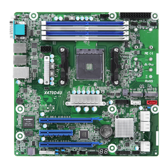
Page 12: Motherboard Layout
DDR4_A2 (64 bit, 288-pin module) LAN1 FAN1 NUT80_2 NUT80_1 ATX12V1 NUT60_2 NUT60_1 LAN2 NUT42_2 NUT42_1 RoHS Socket AM4 PGA 1331 PWM_CFG1 M2_2 M2_1 X470D4U USB3_3_4 BUZZER1 SATA3_0 SATA3_1 SATAPWR1 PCIE6 ASPEED 2500 PCIE5 BAT1 PCIE4 CHASSIS_ID2 CHASSIS_ID3 PANEL1 IPMB_1 BMC_SMB_1... - Page 13 X470D4U Description ATX 12V Power Connector (ATX12V1) 2 x 288-pin DDR4 DIMM Slots (DDR4_A1, DDR4_B1, Blue)* PSU SMBus Header (PSU_SMB1) ATX Power Connector (ATXPWR1) Front Fan Connector (FAN3) Front Fan Connector (FAN4) Front Fan Connector (FAN2) 2 x 288-pin DDR4 DIMM Slots (DDR4_A2, DDR4_B2, White)*...
- Page 14 Description PWM Configuration Header (PWM_CFG1) *For DIMM installation and configuration instructions, please see p.20 (Installation of Memory Modules (DIMM)) for more details.
-
Page 15: Onboard Led Indicators
X470D4U 1.5 Onboard LED Indicators PSU_SMB1 DDR4_B1 (64 bit, 288-pin moule) FAN2 FAN3 FAN4 DDR4_B2 (64 bit, 288-pin module) NUT110_2 NUT110_1 DDR4_A1 (64 bit, 288-pin module) DDR4_A2 (64 bit, 288-pin module) FAN1 NUT80_2 NUT80_1 ATX12V1 NUT60_2 NUT60_1 NUT42_2 NUT42_1 RoHS... - Page 16 Item Status Description SB_PWR1 Green STB PWR ready FAN_LED4 Amber FAN4 failed FAN_LED3 Amber FAN3 failed FAN_LED2 Amber FAN2 failed FAN_LED1 Amber FAN1(CPU) failed FAN_LED5 Amber FAN5 failed FAN_LED6 Amber FAN6 failed BMC_LED1 Green BMC heartbeat LED...
-
Page 17: I/O Panel
X470D4U 1.6 I/O Panel No. Description No. Description UID Switch (UID1) GLAN RJ-45 Port (LAN2)** VGA Port (VGA1) USB 3.1 Gen1 Ports (USB3_1_2) Serial Port (COM1) LAN RJ-45 Port (IPMI_LAN1)* GLAN RJ-45 Port (LAN1)** *There are two LED next to the LAN port. Please refer to the table below for the LAN port LED indications. - Page 18 **There are two LEDs on each LAN port. Please refer to the table below for the LAN port LED indications. ACT/LINK LED SPEED LED LAN Port LAN Port (LAN1, LAN2) LED Indications Activity / Link LED Speed LED Status Description Status Description No Link...
-
Page 19: Block Diagram
X470D4U 1.7 Block Diagram... -
Page 20: Chapter 2 Installation
Chapter 2 Installation This is a micro-ATX form factor (9.6” x 9.6”, 24.4 cm x 24.4 cm) motherboard. Before you install the motherboard, study the configuration of your chassis to ensure that the motherboard fits into it. Make sure to unplug the power cord before installing or removing the motherboard. Failure to do so may cause physical injuries to you and damages to motherboard components. -
Page 21: Installing The Cpu
X470D4U 2.3 Installing the CPU Unplug all power cables before installing the CPU. -
Page 23: Installing The Cpu Fan And Heatsink
X470D4U 2.4 Installing the CPU Fan and Heatsink After you install the CPU into this motherboard, it is necessary to install a larger heatsink and cooling fan to dissipate heat. You also need to spray thermal grease between the CPU and the heatsink to improve heat dissipation. Make sure that the CPU and the heatsink are securely fastened and in good contact with each other. - Page 25 X470D4U...
-
Page 26: Installing Memory Modules (Dimm)
2.5 Installing Memory Modules (DIMM) This motherboard provides four 288-pin DDR4 (Double Data Rate 4) DIMM slots, and supports Dual Channel Memory Technology. 1. For dual channel configuration, you always need to install identical (the same brand, speed, size and chip-type) DDR4 DIMM pairs. 2. - Page 27 X470D4U The DIMM only fits in one correct orientation. It will cause permanent damage to the motherboard and the DIMM if you force the DIMM into the slot at incorrect orientation.
-
Page 28: Expansion Slots (Pci Express Slots)
2.6 Expansion Slots (PCI Express Slots) There are 3 PCI Express slots on this motherboard. PCIE slot: PCIE4 (PCIE 3.0 x16 slot, from CPU) is used for PCI Express x8 lane width cards. PCIE5 (PCIE 3.0 x8 slot, from CPU) is used for PCI Express x4 lane width cards. PCIE6 (PCIE 3.0 x16 slot, from CPU) is used for PCI Express x16 lane width cards. -
Page 29: Jumpers Setup
X470D4U 2.7 Jumpers Setup The illustration shows how jumpers are setup. When the jumper cap is placed on the pins, the jumper is “Short”. If no jumper cap is placed on the pins, the jumper is “Open”. The illustration shows a 3-pin jumper whose pin1 and pin2 are “Short”... - Page 30 Chassis ID1 Jumper (3-pin CHASSIS_ID1) (see p.7, No. 30) Chassis ID2 Jumper (3-pin CHASSIS_ID2) (see p.7, No. 31) Chassis ID3 Jumper (3-pin CHASSIS_ID3) Reserved for system level Reserved for system level (see p.7, No. 29) Chassis ID1 Jumper (3-pin CHASSIS_ID1) (see p.7, No.
-
Page 31: Onboard Headers And Connectors
X470D4U 2.8 Onboard Headers and Connectors Onboard headers and connectors are NOT jumpers. Do NOT place jumper caps over these headers and connectors. Placing jumper caps over the headers and connectors will cause permanent damage to the motherboard. System Panel Header... - Page 32 Auxiliary Panel Header This header supports multiple (18-pin AUX PANEL_1) functions on the front panel, (see p.7, No. 25) including the front panel SMB, internet status indicator and chassis intrusion pin. A. Front panel SMBus connecting pin (6-1 pin FPSMB) This header allows you to connect SMBus (System Management Bus) equipment.
- Page 33 X470D4U Serial ATA3 Connectors These connectors SATA3_1 (SATA3_1: support SATA data see p.7, No. 13) cables for internal (SATA3_2: storage devices with up see p.7, No. 17) to 6.0 Gb/s data transfer (SATA3_3: rate. see p.7, No. 18) (SATA3_4: see p.7, No. 20) (SATA3_5: see p.7, No.
- Page 34 CPU_FAN_SPEED FAN_SPEED_CONTROL to connect a 3-Pin CPU fan, please connect it to Pin 1-3. *For more details, please refer to the Cooler QVL list on the ASRock Rack website. ATX Power Connector This motherboard provides a (24-pin ATXPWR1) 24-pin ATX power connector.
- Page 35 X470D4U Intelligent Platform This 4-pin connector is used IPMB_SDA IPMB_SCL Management Bus Header to provide a cabled base-board (4-pin IPMB_1) or front panel connection for (see p.7, No. 33) value added features and 3rd- No Connect party add-in cards, such as...
-
Page 36: Dr. Debug
2.9 Dr. Debug Dr. Debug is used to provide code information, which makes troubleshooting even easier. Please see the diagrams below for reading the Dr. Debug codes. Code Description Please check if the CPU is installed correctly and then clear CMOS. Problem related to memory, VGA card or other devices. -
Page 37: Unit Identification Purpose Led/Switch
X470D4U 2.10 Unit Identification purpose LED/Switch With the UID button, You are able to locate the server you’re working on from behind a rack of servers. Unit Identification When the UID button on the purpose LED/Switch front or rear panel is pressed,... -
Page 38: M.2_Ssd (Ngff) Module Installation Guide
2.12 M.2_SSD (NGFF) Module Installation Guide The M.2, also known as the Next Generation Form Factor (NGFF), is a small size and versatile card edge connector that aims to replace mPCIe and mSATA. The M.2_SSD (NGFF) Socket 3 (M2_1) can accommodate either a M.2 PCI Express module up to Gen 2 x4 (20Gb/s). - Page 39 X470D4U Step 3 Move the standoff based on the module type and length. The standoff is placed at the nut location D by default. Skip Step 3 and 4 and go straight to Step 5 if you are going to use the default nut.
-
Page 40: Chapter 3 Uefi Setup Utility
Chapter 3 UEFI Setup Utility 3.1 Introduction Th is section explains how to use the UEFI SETUP UTILITY to confi gure your system. Th e UEFI chip on the motherboard stores the UEFI SETUP UTILITY. You may run the UEFI SETUP UTILITY when you start up the computer. -
Page 41: Navigation Keys
X470D4U 3.1.2 Navigation Keys Please check the following table for the function description of each navigation key. Navigation Key(s) Function Description Moves cursor left or right to select Screens Moves cursor up or down to select items + / - To change option for the selected items <Tab>... -
Page 42: Main Screen
3.2 Main Screen Once you enter the UEFI SETUP UTILITY, the Main screen will appear and display the system overview. The Main screen provides system overview information and allows you to set the system time and date. -
Page 43: Advanced Screen
X470D4U 3.3 Advanced Screen In this section, you may set the configurations for the following items: CPU Configuration, Chipset Configuration, Storage Configuration, ACPI Configuration, USB Configuration, Super IO Configuration, H/W Monitor, PSP Firmware Versions, AMD CBS, AMD PBS and Instant Flash. -
Page 44: Cpu Configuration
3.3.1 CPU Configuration PSS Support Enable/disable the generation of ACPI _PPC, _PSS, and _PCT objects. AMD fTPM Switch To select .0: Auto (Depend on Tcg module). 1: Disabled fTPM. 2: OnBoard SPI TPM2.0 SVM Mode Enable/disable CPU Virtualization. CPB Mode Enable/disable CPB. -
Page 45: Chipset Configuration
X470D4U 3.3.2 Chipset Configuration Onboard VGA To enable or disable Onboard VGA. Above 4G Decoding Globally Enables or Disables 64bit capable Devices to be Decoded in Above 4G Address Space (Only if System Supports 64 bit PCI Decoding). SR-IOV Support If system has SR-IOV capable PCIe Devices, this option Enables or Disables Single Root IO Virtualization Support. -
Page 46: Storage Configuration
3.3.3 Storage Configuration PT SATA Port Enable Enable/disable the SATA controllers. PT SATA Mode Select Promontory SATA Type. SATA Hot Plug Enable/disable the SATA Hot Plug Function. -
Page 47: Acpi Configuration
X470D4U 3.3.4 ACPI Configuration PCIE Devices Power On Allow the system to be waked up by a PCIE device and enable wake on LAN. RTC Alarm Power On Use this item to enable or disable RTC (Real Time Clock) to power on the system. -
Page 48: Usb Configuration
3.3.5 USB Configuration Legacy USB Support Use this option to enable or disable legacy support for USB devices. The default value is [Enabled]. -
Page 49: Super Io Configuration
X470D4U 3.3.6 Super IO Configuration Serial Port 1 Configuration Use this item to set parameters of Serial Port 1 (COM1). Serial Port Use this item to enable or disable the serial port. Serial Port Address Use this item to select an optimal setting for Super IO device. -
Page 50: H/W Monitor
3.3.7 H/W Monitor In this section, it allows you to monitor the status of the hardware on your system, includ- ing the parameters of the CPU temperature, motherboard temperature, CPU fan speed, chassis fan speed, and the critical voltage. Fan Control If [Auto] is selected, the fan speed will controlled by BMC. - Page 51 X470D4U FAN 6 This allows you to set the front fan 6’s speed. The default value is [Smart Fan]. Smart Fan Control This allows you to set the Smart fan’s level speed. Smart Fan Duty Control Smart Fan Duty x (x means 1 to 11 stage) This allows you to set duty cycle for each stage.
-
Page 52: Amd Cbs
3.3.8 AMD CBS Zen Common Options Use this item to configure Zen Common options. DF Common Options Use this item to configure DF Common options. UMC Common Options Use this item to configure UMC Common options. NBIO Common Options Use this item to configure NBIO Common options. FCH Common Options Use this item to configure FCH Common options. -
Page 53: Amd Pbs
X470D4U 3.3.9 AMD PBS AMD Firmware Version Show all of AMD Firmware Version. BIOS PSP Support Enable/Disable BIOS PSP driver execution (including all C2P/P2C mailbox, Secure S3, fTPM Support). MITT/WITT Selection Use this item to configure MITT/WITT Selection. LAN Power Enable Enable or disable LAN Power. - Page 54 Clear CMA at warm rst Enable or disable clearing MCA errors at warm reset. If Enabled, just clear MCA status including that MC0: MSR0000_0401, MC1: MSR0000_0405, MC2: MSR0000_0409, MC4: MSR0000_0411 and MC5: MSR0000_0415. Win7 USB Wake Support This option enables USB devices to wake up the system (work with Win7 only). Adjust MEM VDDIO Adjust MEM VDDIO, stepping is 4mV.
- Page 55 X470D4U AMD Fan Policy [Air Cooling] follows platform defined policy, [Water Cooling] forces PWM 100%; Selecting [Fan Control] to [Manual] in CBS will override this option. PcieLanes_4_7_Switch [PT] Pcie Lanes route to PT CHIP; [CPU] Pcie Lane route to CPU PCIE.
-
Page 56: Instant Flash
3.3.10 Instant Flash Instant Flash is a UEFI flash utility embedded in Flash ROM. This convenient UEFI update tool allows you to update system UEFI without entering operating systems ® first like MS-DOS or Windows . Just save the new UEFI file to your USB flash drive, floppy disk or hard drive and launch this tool, then you can update your UEFI only in a few clicks without preparing an additional floppy diskette or other compli- cated flash utility. -
Page 57: Server Mgmt
X470D4U 3.4 Server Mgmt Wait For BMC Wait For BMC response for specified time out. BMC starts at the same time when BIOS starts during AC power ON. It takes around 90 seconds to initialize Host to BMC interfaces. -
Page 58: System Event Log
3.4.1 System Event Log SEL Components Change this to enable ro disable event logging for error/progress codes during boot. Erase SEL Use this to choose options for earsing SEL. When SEL is Full Use this to choose options for reactions to a full SEL. Log EFI Status Codes Use this item to disable the logging of EFI Status Codes or log only error code or only progress code or both. -
Page 59: Bmc Network Configuration
X470D4U 3.4.2 BMC Network Configuration Lan Channel (Failover) Manual Setting IPMI LAN If [No] is selected, the IP address is assigned by DHCP. If you prefer using a static IP address, toggle to [Yes], and the changes take effect after the system reboots. The default value is [No]. - Page 60 The default login information for the IPMI web interface is: Username: admin Password: admin For more instructions on how to set up remote control environment and use the IPMI man- agement platform, please refer to the IPMI Configuration User Guide or go to the Support website at: http://www.asrockrack.com/support/faq.asp...
-
Page 61: Security
X470D4U 3.5 Security In this section, you may set or change the supervisor/user password for the system. For the user password, you may also clear it. Supervisor Password Set or change the password for the administrator account. Only the administrator has authority to change the settings in the UEFI Setup Utility. -
Page 62: Key Management
3.5.1 Key Management In this section, expert users can modify Secure Boot Policy variables without full authenti- cation. Provision Factory Defaults Allow to provision factory default Secure Boot keys when System is in Setup Mode. Install Default Secure Boot Keys Please install default secure boot keys if it’s the first time you use secure boot. - Page 63 X470D4U d) EFI_CERT_SHA256, 384, 512 2. Authenticated UEFI Variable 3. EFI PE/COFF Image(SHA256) Key Source: Default, External, Mixed, Test Key Exchange Keys Enroll Factory Defaults or load certificates from a file: 1. Public Key Certificate in: a) EFI_SIGNATURE_LIST b) EFI_CERT_X509 (DER encoded)
- Page 64 a) EFI_SIGNATURE_LIST b) EFI_CERT_X509 (DER encoded) c) EFI_CERT_RSA2048 (bin) d) EFI_CERT_SHA256, 384, 512 2. Authenticated UEFI Variable 3. EFI PE/COFF Image(SHA256) Key Source: Default, External, Mixed, Test Authorized TimeStamps Enroll Factory Defaults or load certificates from a file: 1. Public Key Certificate in: a) EFI_SIGNATURE_LIST b) EFI_CERT_X509 (DER encoded) c) EFI_CERT_RSA2048 (bin)
-
Page 65: Boot Screen
X470D4U 3.6 Boot Screen In this section, it will display the available devices on your system for you to configure the boot settings and the boot priority. Boot Option #1 Use this item to set the system boot order. Boot Option Filter This option controls Legacy/UEFI ROMs priority. - Page 66 Boot Beep Select whether the Boot Beep should be turned on or off when the system boots up. Please note that a buzzer is needed. Full Screen Logo Use this item to enable or disable OEM Logo. The default value is [Enabled]. AddOn ROM Display Use this option to adjust AddOn ROM Display.
-
Page 67: Csm Parameters
X470D4U 3.6.1 CSM Parameters Enable to launch the Compatibility Support Module. Please do not disable unless you’re running a WHCK test. If you are using Windows Server 2012 R2 or later ver- sions 64-bit UEFI and all of your devices support UEFI, you may also disable CSM for faster boot speed. - Page 68 PCIE6 Slot OpROM Use this item to select slot storage and Network Option ROM policy. In Auto option, the default is Disabled with NVMe device, but it is Legacy with other devices. (This item can't select Video Option ROM policy.)
-
Page 69: Exit Screen
X470D4U 3.7 Exit Screen Save Changes and Exit When you select this option, the following message “Save configuration changes and exit setup?” will pop-out. Press <F10> key or select [Yes] to save the changes and exit the UEFI SETUP UTILITY. -
Page 70: Chapter 4 Software Support
4.2.4 Contact Information If you need to contact ASRock Rack or want to know more about ASRock Rack, welcome to visit ASRock Rack’s website at http://www.ASRockRack.com; or you may contact your... -
Page 71: Chapter 5 Troubleshooting
X470D4U Chapter 5 Troubleshooting 5.1 Troubleshooting Procedures Follow the procedures below to troubleshoot your system. Always unplug the power cord before adding, removing or changing any hardware com- ponents. Failure to do so may cause physical injuries to you and damages to motherboard components. - Page 72 1. Verify if the battery on the motherboard provides ~3VDC. Install a new battery if it does not. 2. Confirm whether your power supply provides adaquate and stable power. Other problems... 1. Try searching keywords related to your problem on ASRock Rack’s FAQ page: http://www.asrockrack.com/support...
-
Page 73: Technical Support Procedures
X470D4U 5.2 Technical Support Procedures If you have tried the troubleshooting procedures mentioned above and the problems are still unsolved, please contact ASRock Rack’s technical support with the following information: 1. Your contact information 2. Model name, BIOS version and problem type.
Need help?
Do you have a question about the X470D4U and is the answer not in the manual?
Questions and answers