Table of Contents
Advertisement
Quick Links
Advertisement
Table of Contents

Related Manuals for ASROCK PRO BTC+ Series


Summary of Contents for ASROCK PRO BTC+ Series
- Page 2 (including damages for loss of profits, loss of business, loss of data, interruption of business and the like), even if ASRock has been advised of the possibility of such damages arising from any defect or error in the documentation or product.
- Page 3 If you require assistance please call ASRock Tel : +886-2-28965588 ext.123 (Standard International call charges apply) The terms HDMI™...
-
Page 4: Table Of Contents
Contents Chapter 1 Introduction Package Contents Specifications Motherboard Layout I/O Panel Chapter 2 Installation Installing the CPU Installing the CPU Fan and Heatsink Installing Memory Modules (DIMM) Expansion Slots (PCI Express Slots and Mining Ports) Jumpers Setup Onboard Headers and Connectors Smart Switches M.2_SSD (NGFF) Module Installation Guide Installing the 4-pin PCIe Power Connectors... - Page 5 4.1.1 UEFI Menu Bar 4.1.2 Navigation Keys Main Screen OC Tweaker Screen Advanced Screen 4.4.1 CPU Configuration 4.4.2 North Bridge Configuration 4.4.3 South Bridge Configuration 4.4.4 Storage Configuration 4.4.5 Super IO Configuration 4.4.6 ACPI Configuration 4.4.7 Trusted Computing 4.4.8 AMD CBS 4.4.9 AMD PBS Tools Hardware Health Event Monitoring Screen...
-
Page 6: Chapter 1 Introduction
If you require technical support related to this motherboard, please visit our website for specific information about the model you are using. You may find the latest VGA cards and CPU support list on ASRock’s website as well. ASRock website http://www.asrock.com. -
Page 7: Specifications
& non-ECC, un-buffered memory* * For Ryzen Series CPUs (Raven Ridge), ECC is only supported with PRO CPUs. * Please refer to Memory Support List on ASRock’s website for more information. (http://www.asrock.com/) • Max. capacity of system memory: 16GB • 15μ Gold Contact in DIMM Slot... - Page 8 • PCIE x1 Gigabit LAN 10/100/1000 Mb/s • Realtek RTL8111EPV • Supports Wake-On-LAN • Supports LAN Cable Detection • Supports Lightning/ESD Protection (ASRock Full Spike Protection) • Supports Energy Efficient Ethernet 802.3az • Supports PXE • Supports DASH Rear Panel • 1 x PS/2 Mouse/Keyboard Port...
- Page 9 Connector • 1 x System Panel Header • 1 x COM Port Header • 1 x Power LED and Speaker Header • 1 x CPU Fan Connector (4-pin) * The CPU Fan Connector supports the CPU fan of maximum 1A (12W) fan power. • 8 x Chassis Fan Connectors (4-pin) * CHA_FAN1~2 support the chassis fan of maximum 1A (12W) fan power.
- Page 10 • ErP/EuP ready (ErP/EuP ready power supply is required) * For detailed product information, please visit our website: http://www.asrock.com Please realize that there is a certain risk involved with overclocking, including adjust- ing the setting in the BIOS, applying Untied Overclocking Technology, or using third- party overclocking tools.
-
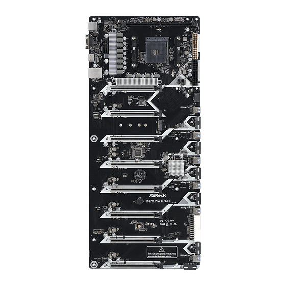
Page 11: Motherboard Layout
1.3 Motherboard Layout CHA_FAN1 RSTBTN1 PWRBTN1 DDR4_A2 (64 bit, 288-pin module) USB_3_4 CPU_FAN1 CHA_FAN2 ATX12V2 SOCKET AM4 ATX12V1 USB 3.1 Gen1 T: USB1 B: USB2 PANEL1 SPK_PLED1 CLRCMOS1 PCIE1 M_Port1 COM1 PCIE2 M_Port2 CHA_FAN3 PCIE3 M_Port3 CHA_FAN4 PCIE4 Promontory X370 CMOS Battery M_Port4... - Page 12 X370 Pro BTC+ No. Description ATX 12V Power Connector (ATX12V2) ATX 12V Power Connector (ATX12V1) Chassis Fan Connector (CHA_FAN1) CPU Fan Connector (CPU_FAN1) 288-pin DDR4 DIMM Slot (DDR4_A2) Reset Button (RSTBTN1) Power Button (PWRBTN1) USB 2.0 Header (USB_3_4) Chassis Fan Connector (CHA_FAN2) ATX Power Connector (ATXPWR2) Power LED and Speaker Header (SPK_PLED1) ATX Power Connector (ATXPWR1)
- Page 13 No. Description Chassis Fan Connector (CHA_FAN4) COM Port Header (COM1) Clear CMOS Jumper (CLRCMOS1)
-
Page 14: I/O Panel
X370 Pro BTC+ 1.4 I/O Panel No. Description No. Description USB 2.0 Ports (USB_1_2) HDMI Port LAN RJ-45 Port* D-Sub Port USB 3.1 Gen1 Ports (USB3_12) PS/2 Mouse/Keyboard Port * There are two LEDs on each LAN port. Please refer to the table below for the LAN port LED indications. ACT/LINK LED SPEED LED LAN Port... -
Page 15: Chapter 2 Installation
Chapter 2 Installation Before you install the motherboard, study the configuration of your chassis to ensure that the motherboard fits into it. Pre-installation Precautions Take note of the following precautions before you install motherboard components or change any motherboard settings. • Make sure to unplug the power cord before installing or removing the motherboard. -
Page 16: Installing The Cpu
X370 Pro BTC+ 2.1 Installing the CPU Unplug all power cables before installing the CPU. -
Page 18: Installing The Cpu Fan And Heatsink
X370 Pro BTC+ 2.2 Installing the CPU Fan and Heatsink After you install the CPU into this motherboard, it is necessary to install a larger heatsink and cooling fan to dissipate heat. You also need to spray thermal grease between the CPU and the heatsink to improve heat dissipation. Make sure that the CPU and the heatsink are securely fastened and in good contact with each other. - Page 20 X370 Pro BTC+ Installing the AM4 Box Cooler SR2...
- Page 22 X370 Pro BTC+...
- Page 23 Installing the AM4 Box Cooler SR3...
- Page 24 X370 Pro BTC+...
- Page 25 4-pin FAN cable USB 2.0 Header Please note that this connector is the interface to the LED control board on the SR3, it requires the AMD utility "SR3 Settings Software" to control the LED. *The diagram shown here are for reference only. Please refer to page 27 for the orientation of USB Header.
-
Page 26: Installing Memory Modules (Dimm)
X370 Pro BTC+ 2.3 Installing Memory Modules (DIMM) This motherboard provides one 288-pin DDR4 (Double Data Rate 4) DIMM slot. It is not allowed to install a DDR, DDR2 or DDR3 memory module into a DDR4 slot; otherwise, this motherboard and DIMM may be damaged. - Page 27 The DIMM only fits in one correct orientation. It will cause permanent damage to the motherboard and the DIMM if you force the DIMM into the slot at incorrect orientation.
-
Page 28: Expansion Slots (Pci Express Slots And Mining Ports)
X370 Pro BTC+ 2.4 Expansion Slots (PCI Express Slots and Mining Ports) There are 8 PCI Express slots and 6 Mining ports on the motherboard. Before installing an expansion card, please make sure that the power supply is switched off or the power cord is unplugged. Please read the documentation of the expansion card and make necessary hardware settings for the card before you start the installation. - Page 29 Ryzen series CPUs (Summit Ridge, Raven Ridge and Pinnacle Ridge): PCIe Slot Mining Port PCIE1 M_Port1 PCIE2 M_Port2 PCIE3 M_Port3 PCIE4 M_Port4 PCIE5 M_Port5 PCIE6 M_Port6 PCIE7 PCIE8...
-
Page 30: Jumpers Setup
X370 Pro BTC+ 2.5 Jumpers Setup The illustration shows how jumpers are setup. When the jumper cap is placed on the pins, the jumper is “Short”. If no jumper cap is placed on the pins, the jumper is “Open”. The illustration shows a 3-pin jumper whose pin1 and pin2 are “Short” when a jumper cap is placed on these 2 pins. -
Page 31: Onboard Headers And Connectors
2.6 Onboard Headers and Connectors Onboard headers and connectors are NOT jumpers. Do NOT place jumper caps over these headers and connectors. Placing jumper caps over the headers and connectors will cause permanent damage to the motherboard. System Panel Header Connect the power (9-pin PANEL1) switch, reset switch and... - Page 32 X370 Pro BTC+ Power LED and Speaker Please connect the Header chassis power LED and (7-pin SPK_PLED1) the chassis speaker to this (see p.6, No. 11) header. Serial ATA3 Connector This SATA3 connector (SATA3_1: supports SATA data see p.6, No. 14) cables for internal storage devices with up to 6.0 Gb/s data transfer rate.
- Page 33 CPU Fan Connector This motherboard pro- (4-pin CPU_FAN1) vides a 4-Pin CPU fan (see p.6, No. 4) (Quiet Fan) connector. FAN_VOLTAGE If you plan to connect a CPU_F AN_SPEED FAN_SPEED_CONTROL 3-Pin CPU fan, please connect it to Pin 1-3. ATX Power Connectors This motherboard pro- (24-pin ATXPWR1) vides two 24-pin ATX...
- Page 34 X370 Pro BTC+ PCIe Power Connectors Please connect these (4-pin PCIE_PWR3) connectors to the power (see p.6, No. 16) supplies. (4-pin PCIE_PWR4) Important: Make sure (see p.6, No. 19) the 4-pin PCIe power (4-pin PCIE_PWR5) connector and the (see p.6, No. 21) external power connector (4-pin PCIE_PWR6) on the graphics card are...
-
Page 35: Smart Switches
2.7 Smart Switches The motherboard has two smart switches: Power Button and Reset Button. Power Button Power Button allows users (PWRBTN1) to quickly turn on/off the (see p.6, No. 7) system. Reset Button Reset Button allows (RSTBTN1) users to quickly reset the (see p.6, No. -
Page 36: M.2_Ssd (Ngff) Module Installation Guide
X370 Pro BTC+ 2.8 M.2_SSD (NGFF) Module Installation Guide The M.2, also known as the Next Generation Form Factor (NGFF), is a small size and versatile card edge connector that aims to replace mPCIe and mSATA. The M.2 Socket supports type 2230/2242/2260/2280 M.2 SATA3 6.0 Gb/s module. Installing the M.2_SSD (NGFF) Module Step 1 Prepare a M.2_SSD (NGFF) module... - Page 37 Step 3 Move the standoff based on the module type and length. The standoff is placed at the nut location D by default. Skip Step 3 and 4 and go straight to Step 5 if you are going to use the default nut. Otherwise, release the standoff by hand.
- Page 38 SATA Transcend TS256GMTS800-256GB Transcend SATA Transcend TS64GMTS400-64GB V-Color SATA V-Color 120G V-Color SATA V-Color 240G SATA WD BLUE WDS100T1B0B-00AS40 SATA WD GREEN WDS240G1G0B-00RC30 For the latest updates of M.2_SSD (NFGG) module support list, please visit our website for details: http://www.asrock.com...
-
Page 39: Installing The 4-Pin Pcie Power Connectors
2.9 Installing the 4-pin PCIe Power Connectors The extra 4-pin PCIe power connectors on this motherboard offer more power for your graphics cards. They provide stable voltages and greatly reduce the risks of burning your motherboard or graphics cards. When the graphics cards are installed, be sure to install the PSU’s 4-pin power cables to the corresponding 4-pin PCIe power connectors (PCIE_ PWR) on your motherboard;... -
Page 40: Special Features
X370 Pro BTC+ 2.10 Special Features 2.10.1 Smart PCIe State Detection This motherboard has included a smart way to show the status of every graphics card. While the system is booting, the Power-On, Self-Test (POST) screen will show the status of the graphics cards that were installed on the motherboard. -
Page 41: Graphics Card Indicator Led
2.10.2 Graphics Card Indicator LED ASRock also placed a faulty graphics card indicator LED behind every mining ports and PCIe slots so you may monitor the status even without a screen. CHA_FAN1 RSTBTN1 PWRBTN1 DDR4_A2 (64 bit, 288-pin module) CPU_FAN1... -
Page 42: Chapter 3 Software And Utilities Operation
X370 Pro BTC+ Chapter 3 Software and Utilities Operation 3.1 Installing Drivers The Support CD that comes with the motherboard contains necessary drivers and useful utilities that enhance the motherboard’s features. Running The Support CD To begin using the support CD, insert the CD into your CD-ROM drive. The CD automatically displays the Main Menu if “AUTORUN”... -
Page 43: Chapter 4 Uefi Setup Utility
Chapter 4 UEFI SETUP UTILITY 4.1 Introduction This section explains how to use the UEFI SETUP UTILITY to configure your system. You may run the UEFI SETUP UTILITY by pressing <F2> or <Del> right after you power on the computer, otherwise, the Power-On-Self-Test (POST) will continue with its test routines. -
Page 44: Navigation Keys
X370 Pro BTC+ 4.1.2 Navigation Keys Use < > key or < > key to choose among the selections on the menu bar, and use < > key or < > key to move the cursor up or down to select items, then press <Enter>... -
Page 45: Main Screen
4.2 Main Screen When you enter the UEFI SETUP UTILITY, the Main screen will appear and display the system overview. -
Page 46: Oc Tweaker Screen
X370 Pro BTC+ 4.3 OC Tweaker Screen In the OC Tweaker screen, you can set up overclocking features. Because the UEFI software is constantly being updated, the following UEFI setup screens and descriptions are for reference purpose only, and they may not exactly match what you see on your screen. - Page 47 Warning: S3 is not supported on systems where SMT is disabled. DRAM Timing Configuration DRAM Frequency If [Auto] is selected, the motherboard will detect the memory module(s) inserted and assign the appropriate frequency automatically. AM4 Advance Boot Training Set TR4 Advance boot training to [Auto] to increase compatibility. Voltage Configuration DRAM Voltage Use this to select DRAM Voltage.
-
Page 48: Advanced Screen
X370 Pro BTC+ 4.4 Advanced Screen In this section, you may set the configurations for the following items: CPU Configuration, North Bridge Configuration, South Bridge Configuration, Storage- Configuration, Super IO Configuration, ACPI Configuration, Trusted Computing , AMD CBS and AMD PBS. Setting wrong values in this section may cause the system to malfunction. -
Page 49: Cpu Configuration
4.4.1 CPU Configuration Cool 'n' Quiet Use this item to enable or disable AMD’s Cool ‘n’ Quiet technology. The default value is ® [Enabled]. Configuration options: [Enabled] and [Disabled]. If you install Windows OS and want to enable this function, please set this item to [Enabled]. Please note that enabling this function may reduce CPU voltage and memory frequency, and lead to system stability or compatibility issue with some memory modules or power supplies. -
Page 50: North Bridge Configuration
X370 Pro BTC+ 4.4.2 North Bridge Configuration SR-IOV Support Enable/disable the SR-IOV (Single Root IO Virtualization Support) if the system has SR-IOV capable PCIe devices. -
Page 51: South Bridge Configuration
4.4.3 South Bridge Configuration Onboard HD Audio Enable/disable onboard HD audio. Set to Auto to enable onboard HD audio and automatically disable it when a sound card is installed. Deep Sleep Configure deep sleep mode for power saving when the computer is shut down. Restore on AC/Power Loss Select the power state after a power failure. -
Page 52: Storage Configuration
X370 Pro BTC+ 4.4.4 Storage Configuration SATA Controller(s) Enable/disable the SATA controllers. SATA Mode AHCI: Supports new features that improve performance. RAID: Combine multiple disk drives into a logical unit. SATA Hot Plug Enable/disable the SATA Hot Plug function. -
Page 53: Super Io Configuration
4.4.5 Super IO Configuration Serial Port Enable or disable the Serial port. Serial Port Address Select the address of the Serial port. PS2 Y-Cable Enable the PS2 Y-Cable or set this option to Auto. -
Page 54: Acpi Configuration
X370 Pro BTC+ 4.4.6 ACPI Configuration Suspend to RAM It is recommended to select auto for ACPI S3 power saving. ACPI HPET Table Enable the High Precision Event Timer for better performance and to pass WHQL tests. PS/2 Keyboard Power On Allow the system to be waked up by a PS/2 Keyboard. -
Page 55: Trusted Computing
4.4.7 Trusted Computing Security Device Support Enable to activate Trusted Platform Module (TPM) security for your hard disk drives. -
Page 56: Amd Cbs
X370 Pro BTC+ 4.4.8 AMD CBS Zen Common Options RedirectForReturnDis From a workaround for GCC/C000005 issue for XV Core on CZ A0, setting MSRC001_1029 Decode Configuration (DE_CFG) bit 14 [DecfgNoRdrctForReturns] to 1. L2 TLB Associativity 0 - L2 TLB ways [11:8] are fully associative. 1 - =L2 TLB ways [11:8] are 4K-only. Platform first Error Handling Enable/disable PFEH, cloak individual banks, and mask deferred error interrupts from each bank. - Page 57 Opcache Control Enables or disables the Opcache. OC Mode OC1 - 16 cores/3.6GHz on 1.3375V OC2 - 8 cores/3.7GHz on 1.369V OC3 - 4 cores/3.75GHz on 1.374V\nMax Stress - 16 cores/3.8GHz on 1.400V SEV-ES ASID Space Limit SEV VMs using ASIDs below the SEV-ES ASID Space Limit must enable the SEV-ES feature. The valid values for this field are from 0x1 (1) - 0x10 (16).
- Page 58 X370 Pro BTC+ GMI encryption control GMI encryption control Control GMI link encryption xGMI encryption control Control xGMI link encryption CC6 memory region encryption Control whether or not the CC6 save/restore memory is encrypted Location of private memory regions Controls whether or not the private memory regions (PSP, SMU and CC6) are at the top of DRAM or distributed.
- Page 59 UMC Common Options DDR4 Common Options DRAM Controller Configuration DRAM Controller Configuration DRAM Power Options Cmd2T Select between 1T and 2T mode on ADDR/CMD Gear Down Mode Configure the Gear Down Mode. CAD Bus Configuration CAD Bus Timing User Controls Setup time on CAD bus signals to Auto or Manual CAD Bus Drive Strength User Controls Drive Strength on CAD bus signals to Auto or Manual...
- Page 60 X370 Pro BTC+ DRAM Memory Mapping Chipselect Interleaving Interleave memory blocks across the DRAM chip selects for node 0. BankGroupSwap Configure the BankGroupSwap. BankGroupSwapAlt Configure BankGroupSwapAlt. Address Hash Bank Configure the bank address hashing. Address Hash CS Configure the CS address hashing. NVDIMM Memory MBIST MBIST Enable...
- Page 61 Determinism Slider [Auto] Use default performance determinism settings cTDP Control [Auto] Use the fused cTDP. [Manual] User can set customized cTDP. Fan Control [Auto] Use the default fan controller settings. [Manual] User can set customized fan controller settings. Disable PSI. ACS Enable Enable ACS.
- Page 62 X370 Pro BTC+ SATA Controller Disable or enable OnChip SATA controller Sata RAS Support Disable or enable Sata RAS Support Sata Disabled AHCI Prefetch Function Configure the Sata Disabled AHCI Prefetch function. Aggresive SATA Device Sleep Port 0 Configure the Aggresive SATA Device Sleep Port 0. Aggresive SATA Device Sleep Port 1 Configure the Aggresive SATA Device Sleep Port 1.
- Page 63 Chipselect Interleaving Interleave memory blocks across the DRAM chip selects for node 0. BankGroupSwap Configure the BankGroupSwap. BankGroupSwapAlt Configure the BankGroupSwapAlt. Address Hash Bank Configure the bank address hashing. Address Hash CS Configure the CS address hashing. NVDIMM Memory MBIST MBIST Enable Configure the Memory MBIST.
-
Page 64: Amd Pbs
X370 Pro BTC+ 4.4.9 AMD PBS The AMD PBS menu accesses AMD specific features. If you want to use the onboard graphics output, please make sure the item “Primary Video Adapter“ is set to [Int Graphics (IGD)]. -
Page 65: Tools
4.5 Tools Easy RAID Installer Easy RAID Installer helps you to copy the RAID driver from the support CD to your USB storage device. After copying the drivers please change the SATA mode to RAID, then you can start installing the operating system in RAID mode. Instant Flash Save UEFI files in your USB storage device and run Instant Flash to update your UEFI. - Page 66 X370 Pro BTC+ Network Configuration Use this to configure internet connection settings for Internet Flash. Internet Setting Enable or disable sound effects in the setup utility. UEFI Download Server Select a server to download the UEFI firmware.
-
Page 67: Hardware Health Event Monitoring Screen
4.6 Hardware Health Event Monitoring Screen This section allows you to monitor the status of the hardware on your system, including the parameters of the CPU temperature, motherboard temperature, fan speed and voltage. CPU Fan 1 Setting Select a fan mode for CPU Fan 1, or choose Customize to set 5 CPU temperatures and assign a respective fan speed for each temperature. - Page 68 X370 Pro BTC+ Chassis Fan 2 Temp Source Select a fan temperature source for Chassis Fan 2. Over Temperature Protection When Over Temperature Protection is enabled, the system automatically shuts down when the motherboard is overheated.
-
Page 69: Security Screen
4.7 Security Screen In this section you may set or change the supervisor/user password for the system. You may also clear the user password. Supervisor Password Set or change the password for the administrator account. Only the administrator has authority to change the settings in the UEFI Setup Utility. Leave it blank and press enter to remove the password. -
Page 70: Boot Screen
X370 Pro BTC+ 4.8 Boot Screen This section displays the available devices on your system for you to configure the boot settings and the boot priority. Fast Boot Fast Boot minimizes your computer's boot time. In fast mode you may not boot from an USB storage device. - Page 71 AddOn ROM Display Enable AddOn ROM Display to see the AddOn ROM messages or configure the AddOn ROM if you've enabled Full Screen Logo. Disable for faster boot speed. Above 4G Decoding Enable or disable 64bit capable Devices to be decoded in Above 4G Address Space (only if the system supports 64 bit PCI decoding).
- Page 72 X370 Pro BTC+ CSM (Compatibility Support Module) Enable to launch the Compatibility Support Module. Please do not disable unless you’re running a WHCK test. Launch PXE OpROM Policy Select UEFI only to run those that support UEFI option ROM only. Select Legacy only to run those that support legacy option ROM only.
-
Page 73: Exit Screen
4.9 Exit Screen Save Changes and Exit When you select this option the following message, “Save configuration changes and exit setup?” will pop out. Select [OK] to save changes and exit the UEFI SETUP UTILITY. Discard Changes and Exit When you select this option the following message, “Discard changes and exit setup?”... - Page 74 Contact Information If you need to contact ASRock or want to know more about ASRock, you’re welcome to visit ASRock’s website at http://www.asrock.com; or you may contact your dealer for further information. For technical questions, please submit a support request form at https://event.asrock.com/tsd.asp...
- Page 75 DECLARATION OF CONFORMITY Per FCC Part 2 Section 2.1077(a) Responsible Party Name: ASRock Incorporation Address: 13848 Magnolia Ave, Chino, CA91710 Phone/Fax No: +1-909-590-8308/+1-909-590-1026 hereby declares that the product Product Name : Motherboard X370 Pro BTC+ Model Number : Conforms to the following speci cations:...
- Page 76 EU Declaration of Conformity For the following equipment: Motherboard (Product Name) X370 Pro BTC+ / ASRock (Model Designation / Trade Name) ASRock Incorporation (Manufacturer Name) 2F., No.37, Sec. 2, Jhongyang S. Rd., Beitou District, Taipei City 112, Taiwan (R.O.C.) (Manufacturer Address) EMC —Directive 2014/30/EU (from April 20th, 2016)
Need help?
Do you have a question about the PRO BTC+ Series and is the answer not in the manual?
Questions and answers