Table of Contents
Advertisement
Version 1.0
Published January 2018
Copyright©2018 ASRock INC. All rights reserved.
Copyright Notice:
No part of this documentation may be reproduced, transcribed, transmitted, or
translated in any language, in any form or by any means, except duplication of
documentation by the purchaser for backup purpose, without written consent of
ASRock Inc.
Products and corporate names appearing in this documentation may or may not
be registered trademarks or copyrights of their respective companies, and are used
only for identification or explanation and to the owners' benefit, without intent to
infringe.
Disclaimer:
Specifications and information contained in this documentation are furnished for
informational use only and subject to change without notice, and should not be
constructed as a commitment by ASRock. ASRock assumes no responsibility for
any errors or omissions that may appear in this documentation.
With respect to the contents of this documentation, ASRock does not provide
warranty of any kind, either expressed or implied, including but not limited to
the implied warranties or conditions of merchantability or fitness for a particular
purpose.
In no event shall ASRock, its directors, officers, employees, or agents be liable for
any indirect, special, incidental, or consequential damages (including damages for
loss of profits, loss of business, loss of data, interruption of business and the like),
even if ASRock has been advised of the possibility of such damages arising from any
defect or error in the documentation or product.
This device complies with Part 15 of the FCC Rules. Operation is subject to the following
two conditions:
(1) this device may not cause harmful interference, and
(2) this device must accept any interference received, including interference that
may cause undesired operation.
CALIFORNIA, USA ONLY
The Lithium battery adopted on this motherboard contains Perchlorate, a toxic substance
controlled in Perchlorate Best Management Practices (BMP) regulations passed by the
California Legislature. When you discard the Lithium battery in California, USA, please
follow the related regulations in advance.
"Perchlorate Material-special handling may apply, see www.dtsc.ca.gov/hazardouswaste/
perchlorate"
ASRock Website: http://www.asrock.com
Advertisement
Table of Contents

Related Manuals for ASROCK X470 Master SLI


Summary of Contents for ASROCK X470 Master SLI
-
Page 1: Copyright Notice
(including damages for loss of profits, loss of business, loss of data, interruption of business and the like), even if ASRock has been advised of the possibility of such damages arising from any defect or error in the documentation or product. - Page 2 If you require assistance please call ASRock Tel : +886-2-28965588 ext.123 (Standard International call charges apply) The terms HDMI™...
- Page 3 CE Warning This device complies with directive 2014/53/EU issued by the Commision of the European Community. This equipment complies with EU radiation exposure limits set forth for an uncontrolled environment. This equipment should be installed and operated with minimum distance 20cm between the radiator &...
-
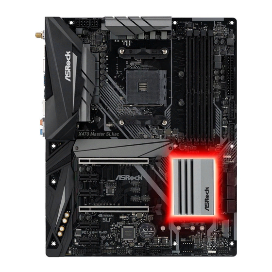
Page 5: Motherboard Layout
X470 Master SLI/ac / X470 Master SLI Motherboard Layout CPU_FAN2/WP ATX12V1 ATX12V2 M2_WIFI_1* CPU_FAN1 USB 3.1 Gen1 T: USB1 B: USB2 USB 3.1 Gen1 T: USB3 B: USB4 USB 3.1 Gen2 T: USB3_TA_1 B: USB3_TC_1 USB 3.1 Gen1 Top: T: USB5... - Page 6 No. Description ATX 12V Power Connector (ATX12V1) ATX 12V Power Connector (ATX12V2) CPU Fan Connector (CPU_FAN1) CPU/Water Pump Fan Connector (CPU_FAN2/WP) 2 x 288-pin DDR4 DIMM Slots (DDR4_A1, DDR4_B1) 2 x 288-pin DDR4 DIMM Slots (DDR4_A2, DDR4_B2) ATX Power Connector (ATXPWR1) USB 3.1 Gen1 Header (USB3_9_10) USB 3.1 Gen1 Header (USB3_7_8) AMD LED Fan USB Header (USB_5)
- Page 7 X470 Master SLI/ac / X470 Master SLI I/O Panel X470 Master SLI/ac No. Description No. Description PS/2 Mouse/Keyboard Port USB 3.1 Gen1 Ports (USB3_5_6) LAN RJ-45 Port* USB 3.1 Gen2 Type-A Port (USB3_TA_1) Central / Bass (Orange) USB 3.1 Gen2 Type-C Port (USB3_TC_1) Rear Speaker (Black) USB 3.1 Gen1 Ports (USB3_3_4)
- Page 8 X470 Master SLI No. Description No. Description PS/2 Mouse/Keyboard Port Optical SPDIF Out Port LAN RJ-45 Port* USB 3.1 Gen1 Ports (USB3_5_6) Central / Bass (Orange) USB 3.1 Gen2 Type-A Port (USB3_TA_1) Rear Speaker (Black) USB 3.1 Gen2 Type-C Port (USB3_TC_1) Line In (Light Blue) USB 3.1 Gen1 Ports (USB3_3_4)
- Page 9 X470 Master SLI/ac / X470 Master SLI * There are two LEDs on each LAN port. Please refer to the table below for the LAN port LED indications. ACT/LINK LED SPEED LED LAN Port Activity / Link LED Speed LED...
- Page 10 WiFi-802.11ac Module and ASRock WiFi 2.4/5 GHz Antennas (for X470 Master SLI/ac only) WiFi-802.11ac + BT Module This motherboard comes with an exclusive WiFi 802.11 a/b/g/n/ac + BT v4.2 module (pre-installed on the rear I/O panel) that offers support for WiFi 802.11 a/b/ g/n/ac connectivity standards and Bluetooth v4.2.
- Page 11 X470 Master SLI/ac / X470 Master SLI WiFi Antennas Installation Guide Step 1 Prepare the WiFi 2.4/5 GHz Antennas that come with the package. Step 2 Connect the two WiFi 2.4/5 GHz Antennas to the antenna connectors. Turn the antenna clock- wise until it is securely connected.
-
Page 12: Chapter 1 Introduction
If you require technical support related to this motherboard, please visit our website for specific information about the model you are using. You may find the latest VGA cards and CPU support list on ASRock’s website as well. ASRock website http://www.asrock.com. -
Page 13: Specifications
* For Ryzen Series CPUs (Raven Ridge), ECC is only supported with PRO CPUs. * Please refer to Memory Support List on ASRock’s website for more information. (http://www.asrock.com/) * Please refer to page 26 for DDR4 UDIMM maximum frequency support. - Page 14 • Supports AMD Quad CrossFireX and CrossFireX • Supports NVIDIA® Quad SLI and SLI • 15μ Gold Contact in VGA PCIe Slot (PCIE1) • Integrated AMD Radeon Graphics Vega Series Graphics in Ryzen Series APU* * Actual support may vary by CPU • DirectX 12, Pixel Shader 5.0 • Max.
- Page 15 X470 Master SLI/ac / X470 Master SLI • 2 x Antenna Ports (for X470 Master SLI/ac only) Rear Panel • 1 x PS/2 Mouse/Keyboard Port • 1 x HDMI Port • 1 x Optical SPDIF Out Port • 1 x USB 3.1 Gen2 Type-A Port (10 Gb/s) (Supports ESD Protection) • 1 x USB 3.1 Gen2 Type-C Port (10 Gb/s) (Supports ESD...
- Page 16 * The CPU/Water Pump Fan supports the water cooler fan of maximum 2A (24W) fan power. • 3 x Chassis/Water Pump Fan Connectors (4-pin) (Smart Fan Speed Control) * The Chassis/Water Pump Fan supports the water cooler fan of maximum 2A (24W) fan power. * CPU_FAN2/WP, CHA_FAN1/WP, CHA_FAN2/WP and CHA_FAN3/WP can auto detect if 3-pin or 4-pin fan is in use.
- Page 17 • ErP/EuP ready (ErP/EuP ready power supply is required) tions * For detailed product information, please visit our website: http://www.asrock.com Please realize that there is a certain risk involved with overclocking, including adjusting the setting in the BIOS, applying Untied Overclocking Technology, or using third-party overclocking tools.
-
Page 18: Chapter 2 Installation
Chapter 2 Installation This is an ATX form factor motherboard. Before you install the motherboard, study the configuration of your chassis to ensure that the motherboard fits into it. Pre-installation Precautions Take note of the following precautions before you install motherboard components or change any motherboard settings. -
Page 19: Installing The Cpu
X470 Master SLI/ac / X470 Master SLI 2.1 Installing the CPU Unplug all power cables before installing the CPU. -
Page 21: Installing The Cpu Fan And Heatsink
X470 Master SLI/ac / X470 Master SLI 2.2 Installing the CPU Fan and Heatsink After you install the CPU into this motherboard, it is necessary to install a larger heatsink and cooling fan to dissipate heat. You also need to spray thermal grease between the CPU and the heatsink to improve heat dissipation. - Page 23 X470 Master SLI/ac / X470 Master SLI Installing the AM4 Box Cooler SR2...
- Page 25 X470 Master SLI/ac / X470 Master SLI 4-pin FAN cable RGB LED Cable +12V *The diagram shown here are for reference only. Please refer to page 35 for the orientation of AMD Fan LED Header (AMD_FAN_LED1).
- Page 26 Installing the AM4 Box Cooler SR3...
- Page 27 X470 Master SLI/ac / X470 Master SLI...
- Page 29 +12V Please note that only one cable should be used at a time in this step. If you select AMD_FAN_LED1, please install ASRock utility "ASRock Polychrome RGB". If you select USB connector, please install AMD utility "SR3 Settings Software". *The diagram shown here are for reference only. Please refer to page 35 for the orientation of AMD Fan...
- Page 30 2.3 Installing Memory Modules (DIMM) This motherboard provides four 288-pin DDR4 (Double Data Rate 4) DIMM slots, and supports Dual Channel Memory Technology. 1. For dual channel configuration, you always need to install identical (the same brand, speed, size and chip-type) DDR4 DIMM pairs. 2.
- Page 31 X470 Master SLI/ac / X470 Master SLI Ryzen Series CPUs (Summit Ridge): UDIMM Memory Slot Frequency (Mhz) 2667 2667 2667 2400-2667 2133-2400 SR/DR SR/DR 1866-2133 Ryzen Series CPUs (Raven Ridge): UDIMM Memory Slot Frequency (Mhz) 2933 2667 2667 2400 2133...
- Page 32 The DIMM only fits in one correct orientation. It will cause permanent damage to the motherboard and the DIMM if you force the DIMM into the slot at incorrect orientation.
- Page 33 X470 Master SLI/ac / X470 Master SLI 2.4 Expansion Slots (PCI Express Slots) There are 6 PCI Express slots on the motherboard. Before installing an expansion card, please make sure that the power supply is switched off or the power cord is unplugged. Please read the documentation of the expansion card and make necessary hardware settings for the card before you start the installation.
-
Page 34: Jumpers Setup
2.5 Jumpers Setup The illustration shows how jumpers are setup. When the jumper cap is placed on the pins, the jumper is “Short”. If no jumper cap is placed on the pins, the jumper is “Open”. The illustration shows a 3-pin jumper whose pin1 and pin2 are “Short” when a jumper cap is placed on these 2 pins. -
Page 35: Onboard Headers And Connectors
X470 Master SLI/ac / X470 Master SLI 2.6 Onboard Headers and Connectors Onboard headers and connectors are NOT jumpers. Do NOT place jumper caps over these headers and connectors. Placing jumper caps over the headers and connectors will cause permanent damage to the motherboard. - Page 36 Power LED and Speaker Please connect the SPEAKER DUMMY Header chassis power LED and DUMMY (7-pin SPK_PLED1) the chassis speaker to this (see p.1, No. 24) header. PLED+ PLED+ PLED- Serial ATA3 Connectors These six SATA3 (SATA3_1_2: connectors support SATA see p.1, No.
- Page 37 X470 Master SLI/ac / X470 Master SLI Front Panel Audio Header This header is for PRESENCE# (9-pin HD_AUDIO1) MIC_RET connecting audio devices OUT_RET (see p.1, No. 27) to the front audio panel. OUT2_L J_SENSE OUT2_R MIC2_R MIC2_L 1. High Definition Audio supports Jack Sensing, but the panel wire on the chassis must support HDA to function correctly.
- Page 38 CPU/Water Pump Fan This motherboard FAN_SPEED FAN_VOLTAGE_CONTROL FAN_SPEED_CONTROL Connector provides a 4-Pin water (4-pin CPU_FAN2/WP) cooling CPU fan (see p.1, No. 4) connector. If you plan to connect a 3-Pin CPU water cooler fan, please connect it to Pin 1-3. ATX Power Connector This motherboard pro- (24-pin ATXPWR1)
- Page 39 X470 Master SLI/ac / X470 Master SLI TPM Header This connector supports Trusted (17-pin TPMS1) Platform Module (TPM) system, (see p.1, No. 25) which can securely store keys, digital certificates, passwords, and data. A TPM system also helps enhance network security, protects digital identities, and ensures platform integrity.
- Page 40 Addressable LED Header This header is used to connect (3-pin ADDR_LED1) Addressable LED extension cable (see p.1, No. 20) which allows users to choose DO_ADDR VOUT from various LED lighting effects. Caution: Never install the Addressable LED cable in the wrong orientation;...
- Page 41 X470 Master SLI/ac / X470 Master SLI 2.7 M.2_SSD (NGFF) Module Installation Guide (M2_1) The M.2, also known as the Next Generation Form Factor (NGFF), is a small size and versatile card edge connector that aims to replace mPCIe and mSATA. The Ultra M.2 Socket (M2_1) supports M Key type 2230/2242/2260/2280/22110 M.2 SATA3 6.0...
- Page 42 Step 3 Before installing a M.2 (NGFF) SSD module, please loosen the screws to remove the M.2 heatsink. Step 4 Gently insert the M.2 (NGFF) SSD module into the M.2 slot. Please be aware that the M.2 (NGFF) SSD module only fits in one orientation. *If you insert Type 22110 M.2 SSD, please make sure that there is no standoff being placed at the nut...
- Page 43 X470 Master SLI/ac / X470 Master SLI M.2_SSD (NGFF) Module Support List Vendor Interface ADATA PCIe ASX8000NP-512GM-C ADATA PCIe ASX7000NP-512GT-C Intel PCIe INTEL 6000P-SSDPEKKF256G7 (nvme) Intel PCIe SSDPEKKF512G7 NVME Kingston PCIe Kingston SHPM2280P2 / 240G (Gen2 x4) Kingston PCIe SKC1000/480G...
- Page 44 2.8 M.2_SSD (NGFF) Module Installation Guide (M2_2) The M.2, also known as the Next Generation Form Factor (NGFF), is a small size and versatile card edge connector that aims to replace mPCIe and mSATA. The M.2 Socket (M2_2) supports M Key type 2230/2242/2260/2280 M.2 SATA3 6.0 Gb/s module and M.2 PCI Express module up to Gen2 x2 (10 Gb/s).
- Page 45 X470 Master SLI/ac / X470 Master SLI Step 3 Move the standoff based on the module type and length. The standoff is placed at the nut location D by default. Skip Step 3 and 4 and go straight to Step 5 if you are going to use the default nut.
- Page 46 Transcend SATA TS512GMTS800 V-Color SATA V-Color 120G V-Color SATA V-Color 240G SATA WD BLUE WDS100T1B0B-00AS40 SATA WD GREEN WDS240G1G0B-00RC30 SATA WD GREEN WDS240G1G0B-00RC30 For the latest updates of M.2_SSD (NFGG) module support list, please visit our website for details: http://www.asrock.com...
- Page 47 X470 Master SLI/ac / X470 Master SLI 2.9 ASRock Polychrome RGB ASRock Polychrome RGB is a lighting control utility specifically designed for unique individuals with sophisticated tastes to build their own stylish colorful lighting system. Simply by connect- ing the LED strip, you can customize various lighting schemes and patterns, including Static, Breathing, Strobe, Cycling, Music, Wave and more.
- Page 48 Connecting the Addressable RGB LED Strip Connect your Addressable RGB LED strip to the Addressable LED Header (ADDR_LED1) on the motherboard. ADDR_LED1 DO_ADDR VOUT 1. Never install the RGB LED cable in the wrong orientation; otherwise, the cable may be damaged. 2.
- Page 49 ASRock Polychrome RGB Utility Now you can adjust the RGB LED color through the ASRock Polychrome RGB utility. Download this utility from the ASRock Live Update & APP Shop and start coloring your PC style your way! Drag the tab to customize your preference.
- Page 50 1 Einleitung Vielen Dank, dass Sie sich für die X470 Master SLI/ac / X470 Master SLI von ASRock entschieden haben – ein zuverlässiges Motherboard, das konsequent unter der strengen Qualitätskontrolle von ASRock hergestellt wurde. Es liefert ausgezeichnete Leistung mit robustem Design, das ASRock Streben nach Qualität und Beständigkeit erfüllt.
-
Page 51: Technische Daten
X470 Master SLI/ac / X470 Master SLI 1.2 Technische Daten • ATX-Formfaktor Plattform • Platine mit zwei Unzen Kupfergehalt • Unterstützt Prozessoren der AMD-AM4-Sockel-Ryzen-Serie Prozessor (Summit Ridge, Raven Ridge und Pinnacle Ridge) • Digi Power design (Intersil) • 12-Leistungsphasendesign • Unterstützt 105-W-Wasserkühlung (Pinnacle Ridge);... - Page 52 • Unterstützt AMD Quad CrossFireX und CrossFireX • Unterstützt NVIDIA® Quad SLI und SLI • 15-μ-Goldkontakt in VGA-PCIe-Steckplatz (PCIE1) • Integrierte Grafikkarte der AMD-Radeon Grafikkarte -Vega-Serie in APU der Ryzen-Serie* * Tatsächliche Unterstützung kann je nach Prozessor variieren • DirectX 12, Pixel Shader 5.0 • Max.
- Page 53 X470 Master SLI/ac / X470 Master SLI • 1 x PS/2-Maus-/Tastaturanschluss (nur beim X470 Master SLI/ Rückblende, • 1 x HDMI-Port • 1 x Optischer SPDIF-Ausgang • 1 x USB 3.1-Gen2-Typ-A-Port (10 Gb/s) (unterstützt Schutz gegen elektrostatische Entladung) • 1 x USB 3.1-Gen2-Typ-C-Port (10 Gb/s) (unterstützt Schutz gegen elektrostatische Entladung) • 6 x USB-3.1-Gen1-Ports (unterstützt Schutz gegen...
- Page 54 * Der CPU-/Wasserpumpenlüfter unterstützt einen Wasserkühler- lüfter mit einer maximalen Lüfterleistung von 2A (24 W). • 3 x Anschlusse für Gehäuse-/Wasserpumpenlüfter (4-polig) (intelligente Lüftergeschwindigkeitssteuerung) * Der Gehäuse-/Wasserpumpenlüfter unterstützt einen Wasserküh- lerlüfter mit einer maximalen Lüfterleistung von 2A (24 W). * CPU_FAN2/WP, CHA_FAN1/WP, CHA_FAN2/WP und CHA_ FAN3/WP können automatisch erkennen, ob ein 3- oder 4-poliger Lüfter verwendet wird.
- Page 55 • FCC, CE Zertifizierun- • ErP/EuP ready (ErP/EuP ready-Netzteil erforderlich) * Detaillierte Produktinformationen finden Sie auf unserer Webseite: http://www.asrock.com Bitte beachten Sie, dass mit einer Übertaktung, zu der die Anpassung von BIOS- Einstellungen, die Anwendung der Untied Overclocking Technology oder die Nutzung von Übertaktungswerkzeugen von Drittanbietern zählen, bestimmte Risiken verbunden...
- Page 56 1.3 Jumpereinstellung Die Abbildung zeigt, wie die Jumper eingestellt werden. Wenn die Jumper-Kappe auf den Kontakten angebracht ist, ist der Jumper „kurzgeschlossen“. Wenn keine Jumper-Kappe auf den Kontakten angebracht ist, ist der Jumper „offen“. Die Abbildung zeigt einen 3-poligen Jumper, dessen Kontakt 1 und Kontakt 2 „kurzgeschlossen“ sind, wenn eine Jumper-Kappe auf diesen 2 Kontakten angebracht ist.
- Page 57 X470 Master SLI/ac / X470 Master SLI 1.4 Integrierte Stiftleisten und Anschlüsse Integrierte Stiftleisten und Anschlüsse sind KEINE Jumper. Bringen Sie KEINE Jumper- Kappen an diesen Stiftleisten und Anschlüssen an. Durch Anbringen von Jumper-Kappen an diesen Stiftleisten und Anschlüssen können Sie das Motherboard dauerhaft beschädigen.
- Page 58 Betrieb-LED- und Bitte verbinden Sie die Betrieb- SPEAKER DUMMY Lautsprecher-Stiftleiste LED des Gehäuses und den DUMMY (7-polig, SPK_PLED1) Gehäuselautsprecher mit dieser (siehe S. 1, Nr. 24) Stiftleiste. PLED+ PLED+ PLED- Serial-ATA-III-Anschlüsse Diese sechs SATA-III-Anschlüsse (SATA3_1_2: unterstützen SATA-Datenkabel siehe S. 1, Nr. 15) für interne Speichergeräte mit (SATA3_3_4: einer Datenübertragungsge-...
- Page 59 X470 Master SLI/ac / X470 Master SLI Audiostiftleiste Diese Stiftleiste dient dem PRESENCE# (Frontblende) MIC_RET Anschließen von Audiogeräten OUT_RET (9-polig, HD_AUDIO1) an der Frontblende. (siehe S. 1, Nr. 27) OUT2_L J_SENSE OUT2_R MIC2_R MIC2_L 1. High Definition Audio unterstützt Anschlusserkennung, der Draht am Gehäuse muss dazu jedoch HDA unterstützt.
- Page 60 CPU-/Wasserpumpen- Dieses Motherboard bietet einen FAN_SPEED FAN_VOLTAGE_CONTROL FAN_SPEED_CONTROL Lüfteranschluss 4-poligen Wasserkühlung-CPU- (4-polig, CPU_FAN2/WP) Lüfteranschluss. Falls Sie einen (siehe S. 1, Nr. 4) 3-poligen CPU-Wasserkühler- lüfter anschließen möchten, verbinden Sie ihn bitte mit Kontakt 1 bis 3. ATX-Netzanschluss Dieses Motherboard bietet einen (24-polig, ATXPWR1) 24-poligen ATX-Netzanschluss.
- Page 61 X470 Master SLI/ac / X470 Master SLI TPM-Stiftleiste Dieser Anschluss unterstützt das (17-polig, TPMS1) Trusted Platform Module- (TPM) (siehe S. 1, Nr. 25) System, das Schlüssel, digitale Zertifikate, Kennwörter und Daten sicher aufbewahren kann. Ein TPM-System hilft zudem bei der Stärkung der Netzwerksicherheit,...
- Page 62 Adressierbare-LED- Diese Stiftleiste dient der Verbind- Stiftleiste ung des Adressierbare-LED-Ver- (3-polig, ADDR_LED1) längerungskabels, womit Nutzer DO_ADDR VOUT (siehe S. 1, Nr. 20) zwischen verschiedenen LED- Lichteffekten wählen können. Achtung: Installieren Sie das Adressierbare-LED-Kabel nie- mals falsch herum; andernfalls könnte das Kabel beschädigt werden.
- Page 63 Internet de ASRock. Site Internet ASRock http://www.asrock.com. 1.1 Contenu de l’emballage • Carte mère ASRock X470 Master SLI/ac / X470 Master SLI (facteur de forme ATX) • Guide d'installation rapide pour la ASRock X470 Master SLI/ac / X470 Master SLI • CD de support pour la ASRock X470 Master SLI/ac / X470 Master SLI...
- Page 64 PRO. * Veuillez consulter la liste de prise en charge des mémoires sur le site Web d'ASRock pour de plus amples informations. (http://www. asrock.com/) * Veuillez consulter la page 26 pour connaître la prise en charge de la fréquence maximale de l'UDIMM DDR4.
- Page 65 X470 Master SLI/ac / X470 Master SLI • Prend en charge AMD Quad CrossFireX et CrossFireX • Prend en charge NVIDIA® Quad SLI et SLI • Contact doré 15μ dans fente VGA PCIe (PCIE1) • Carte graphique AMD Radeon Graphiques série Vega intégrée dans APU...
- Page 66 • 1 x port souris/clavier PS/2 (sur X470 Master SLI/ac Connectique du panneau uniquement) arrière • 1 x port HDMI • 1 x port sortie optique SPDIF • 1 x port USB 3.1 Gen2 type A (10 Go/s) (Protection contre les décharges électrostatiques)
- Page 67 X470 Master SLI/ac / X470 Master SLI * Le ventilateur de processeur /pompe à eau prend en charge un ventilateur de refroidisseur d'eau d'une puissance maximale de 2A (24 W). • 3 x connecteurs pour ventilateur de châssis /pompe à eau (4 broches) (contrôle de vitesse de ventilateur intelligent)
- Page 68 Certifications • ErP/EuP Ready (alimentation ErP/EuP ready requise) * pour des informations détaillées de nos produits, veuillez visiter notre site : http://www.asrock.com Il est important de signaler que l’ o verclocking présente certains risques, incluant des modifica- tions du BIOS, l’ a pplication d’une technologie d’ o verclocking déliée et l’utilisation d’ o utils d’...
- Page 69 X470 Master SLI/ac / X470 Master SLI 1.3 Configuration des cavaliers (jumpers) L’illustration ci-dessous vous renseigne sur la configuration des cavaliers (jumpers). Lorsque le capuchon du cavalier est installé sur les broches, le cavalier est « court-circuité ». Si le capuchon du cavalier n’ e st pas installé sur les broches, le cavalier est « ouvert ». L’illustration représente un cavalier à...
- Page 70 1.4 Embases et connecteurs de la carte mère Les embases et connecteurs situés sur la carte NE SONT PAS des cavaliers. Ne placez JAMAIS de capuchons de cavaliers sur ces embases ou connecteurs. Placer un capuchon de cavalier sur ces embases ou connecteurs endommagera irrémédiablement votre carte mère.
- Page 71 X470 Master SLI/ac / X470 Master SLI Prise DEL d’alimentation Veuillez brancher la DEL SPEAKER DUMMY et haut-parleur d'alimentation du châssis et le DUMMY (SPK_PLED1 à 7 broches) haut-parleur du châssis sur ce (voir p.1, No. 24) connecteur. PLED+ PLED+...
- Page 72 Embase audio du panneau Cette embase sert au frontal branchement des appareils PRESENCE# MIC_RET OUT_RET (HD_AUDIO1 à 9 audio au panneau audio frontal. broches) (voir p.1, No. 27) OUT2_L J_SENSE OUT2_R MIC2_R MIC2_L 1. L’ a udio haute définition prend en charge la technologie Jack Sensing (détection de la fiche), mais le panneau grillagé...
- Page 73 X470 Master SLI/ac / X470 Master SLI Connecteur pour Cette carte mère est dotée d’un FAN_SPEED FAN_VOLTAGE_CONTROL FAN_SPEED_CONTROL ventilateur de processeur / connecteur pour ventilateur de pompe à eau processeur à refroidissement par (CPU_FAN2/WP à 4 eau à 4 broches. Si vous envis-...
- Page 74 Embase TPM Ce connecteur prend en charge un (TPMS1 à 17 broches) module TPM (Trusted Platform (voir p.1, No. 25) Module – Module de plateforme sécurisée), qui permet de sauve- garder clés, certificats numériques, mots de passe et données en toute sécurité.
- Page 75 X470 Master SLI/ac / X470 Master SLI Embase LED adressable Cette embase sert à connecter un (ADDR_LED1 à 3 câble de rallonge LED adress- broches) able permettant aux utilisateurs DO_ADDR VOUT (voir p.1, No. 20) de choisir parmi différents effets lumineux LED.
- Page 76 ASRock senza ulteriore preavviso. Per il supporto tecnico correlato a questa scheda madre, visitare il nostro sito Web per informazioni specifiche relative al modello attualmente in uso. È possibile trovare l'elenco di schede VGA più recenti e di supporto di CPU anche sul sito Web di ASRock. Sito Web di ASRock http://www.asrock.com.
- Page 77 X470 Master SLI/ac / X470 Master SLI 1.2 Specifiche • Fattore di forma ATX Piattaforma • PCB 2oz rame • Supporto di CPU AMD AM4 Socket Ryzen Series (Summit Ridge, Raven Ridge e Pinnacle Ridge) • Digi Power design (Intersil) • Potenza a 12 fasi...
- Page 78 • Supporta AMD Quad CrossFireX e CrossFireX • Supporta NVIDIA® Quad SLI e SLI • Contatti d’ o ro 15μ nell’alloggio VGA PCIe (PCIE1) • Grafica AMD Radeon Grafica serie Vega integrata nelle APU serie Ryzen* * Il supporto effettivo può variare in base alla CPU • DirectX 12, Pixel Shader 5.0 • Memoria condivisa max.
- Page 79 X470 Master SLI/ac / X470 Master SLI • 1 x porta mouse/tastiera PS/2 (solo per X470 Master SLI/ac) I/O pannello • 1 x porta HDMI posteriore • 1 x porta uscita SPDIF ottico • 1 x Porta USB 3.1 Gen2 di tipo A (10 Gb/s) (Supporto protezione ESD) • 1 x Porta USB 3.1 Gen2 di tipo C (10 Gb/s) (Supporto...
- Page 80 * La ventola CPU/ventola pompa dell’acqua supporta ventole di sistemi di raffreddamento ad acqua di potenza massima di 2A (24W). • 3 x connettori ventola telaio/ventola pompa dell’acqua (4 pin) (Controllo intelligente della velocità della ventola) * La ventola Chassis/ventola pompa dell’acqua supporta ventole di sistemi di raffreddamento ad acqua di potenza massima di 2A (24W).
- Page 81 Certificazioni • ErP/EuP Ready (è necessaria alimentazione ErP/EuP ready) * Per informazioni dettagliate sul prodotto, visitare il nostro sito Web: http://www.asrock.com Prestare attenzione al potenziale rischio previsto nella pratica di overclocking, inclusa la regolazione delle impostazioni nel BIOS, l'applicazione di tecnologia di Untied Overclocking o l'utilizzo di strumenti di overclocking di terze parti.
- Page 82 1.3 Impostazione jumper L'illustrazione mostra in che modo vengono impostati i jumper. Quando il cappuccio del jumper è posizionato sui pin, il jumper è "cortocircuitato". Se sui pin non è posizionato alcun cappuccio del jumper, il jumper è "aperto". L'illustrazione mostra un jumper a 3 pin i cui pin1 e pin2 sono "cortocircuitati"...
- Page 83 X470 Master SLI/ac / X470 Master SLI 1.4 Header e connettori su scheda Gli header e i connettori sulla scheda NON sono jumper. NON posizionare cappucci del jumper su questi header e connettori. Il posizionamento di cappucci del jumper su header e connettori provocherà...
- Page 84 Connettore LED Collegare i LED alimentazione e SPEAKER DUMMY alimentazione e altoparlante l’altoparlante a questo connet- a questo connet- DUMMY (SPK_PLED1 a 7 pin) tore. (vedere pag. 1, n. 24) PLED+ PLED+ PLED- Connettori Serial ATA3 Questi sei connettori SATA3 sup- (SATA3_1_2: portano cavi dati SATA per dis- vedere pag.
- Page 85 X470 Master SLI/ac / X470 Master SLI Header audio pannello Questo header serve a collegare PRESENCE# anteriore MIC_RET i dispositivi audio al pannello OUT_RET (AUDIO1_HD a 9 pin) audio anteriore. (vedere pag. 1, n. 27) OUT2_L J_SENSE OUT2_R MIC2_R MIC2_L 1.
- Page 86 Connettore ventola Questa scheda madre è dotata FAN_SPEED FAN_VOLTAGE_CONTROL FAN_SPEED_CONTROL CPU / pompa dell'acqua di un connettore per la ventola (CPU_FAN2/WP della CPU con raffreddamento a 4 pin) ad acqua a 4 pin. Se si decide di (vedere pag. 1, n. 4) collegare una ventola della CPU con raffreddamento ad acqua a 3 pin, collegarla al pin 1-3.
- Page 87 X470 Master SLI/ac / X470 Master SLI Header TPM Questo connettore supporta il (TPMS1 a 17 pin) sistema Trusted Platform Module (vedere pag. 1, n. 25) (TPM), che può archiviare in modo sicuro chiavi, certifi- cati digitali, password e dati. Un...
- Page 88 Header LED indirizzabile Questo header serve a collegare il (ADDR_LED1 a 3 pin) cavo di estensione del LED indir- (vedere pag. 1, n. 20) izzabile che consente di scegliere DO_ADDR VOUT tra vari effetti luce LED. Attenzione: Non installare mai il cavo del LED indirizzabile secondo un orientamento errato, altrimento potrebbe danneg-...
-
Page 89: Contenido Del Paquete
Podrá encontrar las últimas tarjetas VGA, así como la lista de compatibilidad de la CPU, en el sitio web de ASRock. Sitio web de ASRock http://www.asrock.com. - Page 90 * Para CPU de la serie Ryzen (Raven Ridge), ECC solamente se admite con CPU PRO. * Para obtener más información, consulte la lista de memorias compatibles en el sitio web de ASRock. (http://www.asrock.com/) * Consulte la página 26 para conocer las frecuencias máximas compatibles de DDR4 UDIMM.
- Page 91 X470 Master SLI/ac / X470 Master SLI • Compatible con AMD Quad CrossFireX y CrossFireX • Compatible con NVIDIA® Quad SLI y SLI • Contacto 15μGold en ranura VGA PCIe (PCIE1) • Tarjeta gráfica de la serie AMD Radeon Gráficos...
- Page 92 • 1 x puerto de ratón/teclado PS/2 (solo para X470 Master SLI/ac) E/S en panel • 1 x puerto HDMI posterior • 1 x puerto de salida SPDIF óptica • 1 x Puerto USB 3.1 Gen2 Tipo A Port (10 Gb/s) (admite protección ESD)
- Page 93 X470 Master SLI/ac / X470 Master SLI * El ventilador de la CPU/bomba de agua admite ventilador del disipador por agua con una potencia de ventilador máxima de 2A (24 W). • 3 x Conectores (4 contactos) para el ventilador de la bomba de...
- Page 94 • Preparado para ErP/EuP (se necesita una fuente de aliment- ación preparada para ErP/EuP) * Para obtener información detallada del producto, visite nuestro sitio Web: http://www.asrock.com Tenga en cuenta que hay un cierto riesgo implícito en las operaciones de overclocking, incluido el ajuste de la BIOS, aplicando la tecnología de overclocking liberada o utilizando...
- Page 95 X470 Master SLI/ac / X470 Master SLI 1.3 Instalación de los puentes La instalación muestra cómo deben instalarse los puentes. Cuando la tapa de puente se coloca en los contactos, el puente queda “Corto”. Si no coloca la tapa de puente en los contactos, el puente queda “Abierto”.
- Page 96 1.4 Conectores y cabezales incorporados Los cabezales y conectores incorporados NO son puentes. NO coloque tapas de puente so- bre estos cabezales y conectores. Si coloca tapas de puente sobre los cabezales y conectores dañará de forma permanente la placa base. Cabezal del panel del Conecte el interruptor de PLED+...
- Page 97 X470 Master SLI/ac / X470 Master SLI LED de alimentación y Conecte el LED de alimentación SPEAKER DUMMY base de conexiones para la del chasis y el altavoz del chasis a DUMMY altavoz esta base de conexiones. (SPK_PLED1 de 7...
- Page 98 Cabezal de audio del panel Este cabezal se utiliza para frontal conectar dispositivos de audio al PRESENCE# MIC_RET OUT_RET (HD_AUDIO1 de 9 panel de audio frontal. contactos) (consulte la pág.1, N.º 27) OUT2_L J_SENSE OUT2_R MIC2_R MIC2_L 1. El Audio de Alta Definición (HDA, en inglés) es compatible con el método de sensor de conectores, sin embargo, el cable del panel del chasis deberá...
- Page 99 X470 Master SLI/ac / X470 Master SLI Conector del ventilador de Esta placa base proporciona un FAN_SPEED la bomba de agua/CPU conector de ventilador de CPU de FAN_VOLTAGE_CONTROL FAN_SPEED_CONTROL (CPU_FAN2/WP de 4 refrigeración por agua de 4 con- contactos) tactos. Si tiene pensando conectar (consulte la pág.1, N.º...
- Page 100 Cabezal TPM Este conector es compatible con el (TPMS1 de 17 contactos) sistema Módulo de Plataforma Se- (consulte la pág.1, N.º 25) gura (TPM, en inglés), que puede almacenar de forma segura claves, certificados digitales, contraseñas y datos. Un sistema TPM también ayuda a aumentar la seguridad en la red, protege las identidades digitales y garantiza la integridad...
- Page 101 X470 Master SLI/ac / X470 Master SLI Base de conexiones de La base de conexiones se usa para LED direccionable conectar el alargador de LED (ADDR_LED1 direccionable que permite a los DO_ADDR VOUT de 3 contactos) usuarios elegir entre varios efectos (consulte la pág.1, N.º...
- Page 102 • Системная плата ASRock X470 Master SLI/ac / X470 Master SLI (форм-фактор ATX) • Краткое руководство по установке платы ASRock X470 Master SLI/ac / X470 Master • Компакт-диск с документацией к плате ASRock X470 Master SLI/ac / X470 Master SLI • 1 x экран панели с портами ввода-вывода...
- Page 103 X470 Master SLI/ac / X470 Master SLI 1.2. Технические характеристики • Форм-фактор ATX Платформа • Медная печатная плата (2 унции) • Поддерживаются процессоры AMD серии Ryzen под сокет ЦП AM4 (Summit Ridge, Raven Ridge и Pinnacle Ridge) • Digi Power design (Intersil) • Система...
- Page 104 • Поддержка двух диапазонов (2,4/5 ГГц) X470 Master SLI/ • П о д д е р ж к а в ы с о к о с к о р о с т н о г о б е с п р о в о д н о г о...
- Page 105 X470 Master SLI/ac / X470 Master SLI • 1 x порт PS/2 для мыши/клавиатуры (только для X470 Master Порты ввода- вывода на SLI/ac) задней панели • 1 x порт HDMI • 1 x оптический выход SPDIF • 1 x порт USB 3.1 Gen2 Type-A (10 Гбит/с) (с защитой от...
- Page 106 • 1 x разъем для вентилятора охлаждения ЦП, 4-контактный * Разъем процессорного вентилятора поддерживает вентилятор с потребляемым током не более 1 А (12 Вт). • 1 x разъем для вентилятора или водяной помпы водяного охлаждения ЦП (4-контактный) (смарт-регулятор скорости вентилятора) * Разъем для процессорного корпусного вентилятора или водяной...
- Page 107 Сертификация • Совместимость с ErP/EuP (необходим блок питания, соответствующий стандарту ErP/EuP) * С дополнительной информацией об изделии можно ознакомиться на веб-сайте: http://www.asrock.com Следует учитывать, что разгон процессора, включая изменение настроек BIOS, применение технологии Untied Overclocking и использование инструментов разгона независимых производителей, сопряжен с определенным риском. Разгон процессора...
- Page 108 1.3 Установка перемычек Установка перемычек показана на рисунке. При установке перемычки-колпачка на контакты перемычка «замкнута». Если перемычка-колпачок на контакты не установлена, перемычка «разомкнута». На рисунке показана 3-контактная перемычка с замкнутыми контактами 1 и 2 при установке на них перемычки-колпачка. Перемычка сброса настроек...
- Page 109 X470 Master SLI/ac / X470 Master SLI 1.4 Колодки и разъемы, расположенные на системной плате Расположенные на системной плате колодки и разъемы НЕ являются перемычками. НЕ устанавливайте на эти колодки и разъемы перемычки-колпачки. Установка перемычек- колпачков на эти колодки и разъемы может вызвать неустранимое повреждение...
- Page 110 Колодка светодиодного Предназначена для SPEAKER индикатора питания и подключения светодиодного DUMMY DUMMY динамика корпуса индикатора питания и (7-контактная, динамика корпуса. SPK_PLED1) (см. стр. 1, № 24) PLED+ PLED+ PLED- Разъемы Serial ATA3 Эти шесть разъемов (SATA3_1_2: SATA3 предназначены для см. стр. 1, № 15) подключения...
- Page 111 X470 Master SLI/ac / X470 Master SLI Аудиоколодка передней Эта колодка предназначена панели для подключения PRESENCE# MIC_RET (9-контактов, аудиоустройств к передней OUT_RET HD_AUDIO1) аудиопанели. (см. стр. 1, № 27) OUT2_L J_SENSE OUT2_R MIC2_R MIC2_L 1. Аудиосистема высокого разрешения поддерживает функцию распознавания разъема, но...
- Page 112 Разъем для Данная материнская плата FAN_SPEED FAN_VOLTAGE_CONTROL FAN_SPEED_CONTROL вентилятора оснащена 4-контактным или помпы водяного разъемом для системы охлаждения ЦП водяного охлаждения ЦП. (4-контактный 3-контактную систему CPU_FAN2/WP) водяного охлаждения (см. стр. 1, № 4) ЦП следует подключать к контактам 1–3. Разъем питания АТХ Эта...
- Page 113 X470 Master SLI/ac / X470 Master SLI Колодка ТРМ Этот разъем обеспечивает (17-контактов, TPMS1) поддержку системы Trusted (см. стр. 1, № 25) Platform Module (TPM), которая способна обеспечить надежное хранение ключей, цифровых сертификатов, паролей и данных. Система ТРМ также повышает уровень сетевой...
- Page 114 колодка адресуемой Эта колодка служит для светодиодной подсветки подключения удлинительного (3 контакта, кабеля адресуемой DO_ADDR VOUT ADDR_LED1) светодиодной подсветки, (см. стр. 1, № 20) которая позволяет реализовать различные световые эффекты. Внимание! Категорически запрещается подключать кабель адресуемой светодиодной подсветки с нарушением полярности, так как...
- Page 115 • Placa-mãe ASRock X470 Master SLI/ac / X470 Master SLI (ATX Form Factor) • Guia de Instalação Rápida da Placa-mãe ASRock X470 Master SLI/ac / X470 Master SLI • CD de Suporte da Placa-mãe ASRock X470 Master SLI/ac / X470 Master SLI • 1 x Painel de E/S...
- Page 116 * Para CPUs série Ryzen (Raven Ridge), ECC só é suportado com CPUs PRO. * Por favor, consulte a Lista de Suporte de Memória no site da ASRock para obter mais informação. (http://www.asrock.com/) * Por favor consulte a página 26 para suporte de frequência máxima DDR4 UDIMM.
- Page 117 X470 Master SLI/ac / X470 Master SLI • Suporta AMD Quad CrossFireX e CrossFireX • Suporta Quad SLI e SLI da NVIDIA® • Contato em Ouro 15μ no Slot PCIe VGA (PCIE1) • AMD Radeon Gráficos Integrado Série Vega Gráficas na Série Ryzen...
- Page 118 • 1 x Porta PS/2 para mouse/teclado (para X470 Master SLI/ac E/S do painel posterior somente) • 1 x Porta HDMI • 1 x Porta de saída SPDIF ótica • 1 x Porta USB 3.1 Gen2 Tipo A (10 Gb/s) (Suporta Proteção ESD) • 1 x Porta USB 3.1 Gen2 Tipo C (10 Gb/s) (Suporta Proteção...
- Page 119 X470 Master SLI/ac / X470 Master SLI * O Ventilador de CPU/Ventilador da Bomba de Água suporta o ventilador de refrigerador a água de 2A máximo (24W) potência do ventilador. • 3 x Conectores de Ventilador de Chassi/Ventilador da Bomba de Água (4 pinos) (Controle de Velocidade de Ventoinha Inteli-...
- Page 120 • Preparada para ErP/EuP (é necessária uma fonte de alimen- tação preparada para ErP/EuP) * Para obter informações detalhadas sobre o produto, por favor, visite o nosso site: http://www.asrock.com Por favor, observe que existe um certo risco envolvendo overclocking, incluindo o ajuste das definições na BIOS, a aplicação de tecnologia Untied Overclocking ou a utilização...
- Page 121 X470 Master SLI/ac / X470 Master SLI 1.3 Configuração dos jumpers A imagem abaixo mostra como os jumpers são configurados. Quando a tampa do jumper é colocada nos pinos, o jumper é "Curto". Se não for colocada uma tampa de jumper nos pinos, o jumper é...
- Page 122 1.4 Suportes e conectores onboard Os conectores e suportes onboard NÃO são jumpers. NÃO coloque tampas de jumpers sobre estes terminais e conectores Colocar tampas de jumpers sobre os terminais e conec- tores irá causar danos permanentes à placa-mãe. Suporte do painel de Ligue o botão de alimentação, PLED+ PLED-...
- Page 123 X470 Master SLI/ac / X470 Master SLI LED de alimentação e Conecte o LED de alimentação SPEAKER DUMMY Cabeçote de Autofalante do chassi e o autofalante do DUMMY (SPK_PLED1 de 7 pinos) chassi a este cabeçote. (ver p.1, N.º 24)
- Page 124 Suporte de áudio do painel Este suporte destina-se à PRESENCE# frontal MIC_RET conexão dos dispositivos de OUT_RET (HD_AUDIO1 de 9 pinos) áudio no painel de áudio frontal. (ver p.1, N.º 27) OUT2_L J_SENSE OUT2_R MIC2_R MIC2_L 1. O Áudio de alta definição suporta Sensor de Adaptador, mas o fio do painel no chassi deverá...
- Page 125 X470 Master SLI/ac / X470 Master SLI Conector da ventoinha Esta placa mãe inclui um conec- FAN_SPEED FAN_VOLTAGE_CONTROL FAN_SPEED_CONTROL de bomba de água/CPU tor de ventilador da CPU de (CPU_FAN2/WP de 4 refrigeração a água de 4 pinos. pinos) Se você pretende conectar um (ver p.1, N.º...
- Page 126 Suporte TPM Este conector suporta um sistema (TPMS1 de 17 pinos) com Módulo de Plataforma Con- (ver p.1, N.º 25) fiável (TPM), que pode armazenar com segurança chaves, certifica- dos digitais, senhas e dados. Um sistema TPM também ajuda a melhorar a segurança de rede, a proteger identidades digitais e a garantir a integridade da plata-...
- Page 127 X470 Master SLI/ac / X470 Master SLI Plataforma de LED Esta plataforma é usada para Ajustável conectar caboi de extensão (ADDR_LED1 3 pinos) Ajustável de LED que permite aos DO_ADDR VOUT (ver p.1, N.º 20) usuários escolher entre vários efei- tos de iluminação de LED.
- Page 128 ASRock, można także pobrać listę najnowszych kart VGA i obsługiwanych CPU. Strona internetowa ASRock http://www.asrock.com. 1.1 Zawartość opakowania • Płyta główna ASRock X470 Master SLI/ac / X470 Master SLI (Współczynnik kształtu ATX) • Skrócona instrukcja instalacji ASRock X470 Master SLI/ac / X470 Master SLI • Pomocnicza płyta CD ASRock X470 Master SLI/ac / X470 Master SLI...
- Page 129 X470 Master SLI/ac / X470 Master SLI 1.2 Specyfikacje • Współczynnik kształtu ATX Platforma • PCB z 2 uncjami miedzi • Obsługa CPU serii AMD AM4 Socket Ryzen (Summit Ridge, Raven Ridge oraz Pinnacle Ridge) • Digi Power design (Intersil) • Sekcja zasilania 12 Power Phase Design...
- Page 130 • Obsługa AMD Quad CrossFireX i CrossFireX • Obsługa NVIDIA® Quad SLI i SLI • 15μ pozłacany styk w gnieździe VGA PCIe (PCIE1) • Zintegrowana karta graficzna AMD Radeon Grafika serii Vega w APU serii Ryzen* * Rzeczywista obsługa zależy od CPU • DirectX 12, Pixel Shader 5.0 • Maks.
- Page 131 X470 Master SLI/ac / X470 Master SLI • 1 x port myszy/klawiatury PS/2 (X470 Master SLI/ac) Tylny panel • 1 x port HDMI Wejścia/Wyjścia • 1 x port optycznego wyjścia SPDIF • 1 x port USB 3.1 Gen2 typu A (10 Gb/s) (Obsługa zabezpieczenia ESD) • 1 x port USB 3.1 Gen2 typu C (10 Gb/s) (Obsługa...
- Page 132 * Złącze wentylatora CPU/pompy wodnej obsługuje wentylator układu chłodzenia maksymalnym prądem zasilania wentyla- tora 2A (24W). • 3 x złącza wentylatora obudowy/pompy wodnej (4-pinowe) (Inteligentne sterowanie prędkością obrotową wentylatora) * Złącze wentylatora obudowy/pompy wodnej obsługuje wentylator układu chłodzenia maksymalnym prądem zasilania wentylatora 2A (24W).
- Page 133 X470 Master SLI/ac / X470 Master SLI • Microsoft® Windows® 10 64-bitowy System operacyjny • FCC, CE Certyfikaty • Gotowość do obsługi ErP/EuP (Wymagane zasilanie z gotowością obsługi ErP/EuP) * Dla uzyskania szczegółowej informacji o produkcie, należy odwiedzić naszą stronę internetową: http://www.asrock.com...
- Page 134 1.3 Ustawienia zworek Ta ilustracja pokazuje ustawienia zworek. Po umieszczeniu nasadki zworki na pinach, zworka jest “Zwarta”. Jeśli nasadka zworki nie jest umieszczona na pinach, zworka jest “Otwarta”. Ta ilustracja pokazuje 3-pinową zworkę, której pin1 i pin2 są “Zwarte”, a nasadka zworki jest umieszczona na tych 2 pinach.
- Page 135 X470 Master SLI/ac / X470 Master SLI 1.4 Wbudowane złącza główkowe i inne złącza Wbudowane złącza główkowe i inne złącza są bezzworkowe. NIE należy umieszczać zworek nad tymi złączami główkowymi i złączami. Umieszczanie zworek nad złączami główkowymi i złączami spowoduje trwałe uszkodzenie płyty głównej.
- Page 136 Dioda LED zasilania i Podłącz to tego złącza SPEAKER DUMMY złącze główkowe głośnika główkowego diodę LED zasilania DUMMY (7-pinowe SPK_PLED1) obudowy i głośnik obudowy . (sprawdź p.1, Nr 24) PLED+ PLED+ PLED- Złącza Serial ATA3 Te sześć złączy SATA3 obsługuje (SATA3_1_2: kable danych SATA dla sprawdź...
- Page 137 X470 Master SLI/ac / X470 Master SLI Złącze główkowe audio To złącze główkowe służy do PRESENCE# panelu przedniego MIC_RET podłączania urządzeń audio do OUT_RET (9-pinowe HD_AUDIO1) przedniego panelu audio. (sprawdź p.1, Nr 27) OUT2_L J_SENSE OUT2_R MIC2_R MIC2_L 1. High Definition Audio obsługuje wykrywanie gniazda, ale aby działać prawidłowo przewód panelu na obudowie musi obsługiwać...
- Page 138 Złącze wentylatora Ta płyta główna udostępnia FAN_SPEED FAN_VOLTAGE_CONTROL FAN_SPEED_CONTROL pompy wodnej /CPU 4-pinowe złącze obudowy (4-pinowe CPU_FAN2/ wentylatora chłodzenia wod- nego CPU. Jeśli planowane (sprawdź p.1, Nr 4) jest podłączenie 3-pinowego wentylatora chłodzenia wodnego CPU, należy je podłączyć do pinów 1-3. Złącze zasilania ATX Ta płyta główna udostępnia (24-pinowe ATXPWR1)
- Page 139 X470 Master SLI/ac / X470 Master SLI Złącze główkowe TPM To złącze obsługuje system Trust- (17-pinowe TPMS1) ed Platform Module (TPM), który (sprawdź p.1, Nr 25) może bezpiecznie przechowywać klucze, certyfikaty cyfrowe, hasła i dane. System TPM pomaga także w zwiększeniu zabezpiec-...
- Page 140 Adresowalne złącze To złącze główkowe RGB jest główkowe LED używane do podłączenia adresow- (3-pinowe ADDR_LED1) alnego przedłużacza LED, który DO_ADDR VOUT (sprawdź p.1, Nr 20) umożliwia użytkownikom wybór spośród różnych efektów światła LED. Ostrzeżenie: Nigdy nie należy instalować adresowalnego kabla LED w nieprawidłowym kierunku;...
- Page 141 • 시리얼 ATA (SATA) 데이터 케이블 2 개 ( 선택 품목 ) • ASRock SLI_HB_Bridge_2S 카드 1 개 ( 선택 품목 ) • M.2 소켓용 나사 2 개 ( 선택 품목 ) • ASRock WiFi 2.4/5 GHz 안테나 2 개 ( 선택 품목 ) (X470 Master SLI/ac 전용 )
- Page 142 모리를 지원합니다 .* * Ryzen Series CPU(Raven Ridge) 의 경우 , ECC 는 PRO CPU 에 서만 지원합니다 . * 추가 정보를 원하시면 ASRock 웹사이트에 있는 메모리 지원 목록을 참조하십시오 . (http://www.asrock.com/) * DDR4 UDIMM 최대 주파수 지원은 26 페이지를 참조하십시...
- Page 143 X470 Master SLI/ac / X470 Master SLI • AMD Quad CrossFireX 및 CrossFireX 지원 • NVIDIA® Quad SLI 및 SLI 지원 • VGA PCIe 슬롯에 15 µ Gold Contact 장착 (PCIE1) • Ryzen Series APU 의 통합형 AMD Radeon 그래픽...
- Page 144 • PS/2 마우스 / 키보드 포트 1 개 (X470 Master SLI/ac 전용 ) 후면 패널 I/O • HDMI 포트 1 개 • 광학 SPDIF 출력 포트 1 개 • USB 3.1 Gen2 타입 A 포트 1 개 (10 Gb/s) (ESD 보호 지원 ) •...
- Page 145 X470 Master SLI/ac / X470 Master SLI * CPU/ 워터 펌프 팬은 팬 전력이 최대 2A(24W) 인 수냉식 쿨 러 팬을 지원합니다 . • 섀시 / 워터 펌프 팬 커넥터 (4 핀 ) 3 개 ( 스마트 팬 속도 제...
- Page 146 인증 • ErP/EuP 사용 가능 (ErP/EuP 사용 가능 전원공급장치 필요 ) * 자세한 제품 정보에 대해서는 당사 웹사이트를 참조하십시오 : http://www.asrock.com BIOS 설정을 조정하거나 Untied Overclocking Technology 를 적용하거나 타업체 의 오버클로킹 도구를 사용하는 것을 포함하는 오버클로킹에는 어느 정도의 위...
- Page 147 X470 Master SLI/ac / X470 Master SLI 1.3 점퍼 설정 그림은 점퍼를 어떻게 설정하는지 보여줍니다 . 점퍼 캡을 핀에 씌우면 점퍼가 “ 단 락” 됩니다 . 점퍼 캡을 핀에 씌우지 않으면 점퍼가 “ 단선” 됩니다 . 그림은 3 핀 점...
- Page 148 1.4 온보드 헤더 및 커넥터 온보드 헤더와 커넥터는 점퍼가 아닙니다 . 점퍼 캡을 온보드 헤더와 커넥터에 씌우지 마십시오 . 점퍼 캡을 온보드 헤더와 커넥터에 씌우면 마더보드가 영구 적으로 손상됩니다 . 시스템 패널 헤더 섀시의 전원 스위치 , 리셋 스 PLED+ PLED- (9 핀...
- Page 149 X470 Master SLI/ac / X470 Master SLI 전원 LED 및 스피커 헤더 섀시 전원 LED 와 섀시 스피커 SPEAKER DUMMY (7 핀 SPK_PLED1) 를 이 헤더에 연결하십시오 . DUMMY (1 페이지 , 24 번 항목 참조 ) PLED+ PLED+ PLED- 시리얼...
- Page 150 전면 패널 오디오 헤더 이 헤더는 오디오 장치를 전면 PRESENCE# (9 핀 HD_AUDIO1) MIC_RET 오디오 패널에 연결하는 데 사 OUT_RET (1 페이지 , 27 번 항목 참조 ) 용됩니다 . OUT2_L J_SENSE OUT2_R MIC2_R MIC2_L 1. 고음질 오디오는 잭 감지를 지원하지만 올바르게 작동하려면 섀시의 패널 와 이어가...
- Page 151 X470 Master SLI/ac / X470 Master SLI FAN_SPEED CPU/ 워터 펌프 이 마더보드에는 4 핀 수냉식 FAN_VOLTAGE_CONTROL FAN_SPEED_CONTROL 팬 커넥터 CPU 팬 커넥터가 탑재되어 있 (4 핀 CPU_FAN2/WP) 습니다 . 3 핀 CPU 수냉식 쿨러 (1 페이지 , 4 번 항목 참조 ) 팬을...
- Page 152 TPM 헤더 이 커넥터는 키 , 디지털 인증 (17 핀 TPMS1) 서 , 암호 및 데이터를 안전하 (1 페이지 , 25 번 항목 참조 ) 게 보관할 수 있는 TPM(Trusted Platform Module) 시스템을 지원 합니다 . TPM 시스템은 네트워 크 보안을 강화하고 , 디지털 신 원을...
- Page 153 X470 Master SLI/ac / X470 Master SLI 주소 지정 가능한 LED 헤더 이 헤더는 사용자가 다양한 LED (3 핀 ADDR_LED1) 조명 효과에서 선택할 수 있는 (1 페이지 , 20 번 항목 참조 ) 주소 지정 가능한 LED 연장 케 DO_ADDR VOUT 이블을...
- Page 154 • 1 x I/O パネルシールド • 2 x シリアル ATA (SATA) データケーブル (オプション) • 1 x ASRock SLI_HB_Bridge_2S カード (オプション) • 2 x M.2 ソケッ ト用ねじ (オプション) • 2 x ASRock WiFi 2.4/5 GHz アンテナ (オプション) ( X470 Master SLI/ac 専用)...
- Page 155 X470 Master SLI/ac / X470 Master SLI 1.2 仕様 • ATX フォームファクタ プラッ ト • 2 オンスのコパー製 PCB フォーム • AMD AM4 ソケッ ト Ryzen シリーズ CPU (Summit Ridge、 Raven Ridge および Pinnacle Ridge) に対応 • デジタル電源設計 (Intersil) • 12 電源フェーズ設計...
- Page 156 と CrossFireX をサポート • AMD Quad CrossFireX および SLI をサポート • NVIDIA® Quad SLI • VGA PCIe スロッ トに 15 μゴールドコンタク トを採用 (PCIE1) Vega シリーズグラフ ィ ックスを Ryzen シリー グラフ ィ ッ クス • AMD Radeon ズ APU に統合 * * 実際のサポートは...
- Page 157 X470 Master SLI/ac / X470 Master SLI • 1 x PS/2 マウス / キーボードポート (X470 Master SLI/ac 専用) リアパネル I/O • 1 x HDMI ポート • 1 x 光 SPDIF 出力ポート • 1 x USB 3.1 Gen2 Type-A ポート (10 Gb/s) ( 静電気放電 (ESD)...
- Page 158 * CPU/ ウォーターポンプファンは最大 2A (24W) の出力のウォ ータークーラーに対応します。 • 3 x シャーシ / ウォーターポンプファンコネクタ (4 ピン) ( スマ ートファン速度制御) * シャーシ / ウォーターポンプファンは最大 2A (24W) の出力の ウォータークーラーに対応します。 * CPU_FAN2/WP、 CHA_FAN1/WP、 CHA_FAN2/WP および CHA_FAN3/WP は 3 ピンまたは 4 ピンファンが使用されている かどうかを自動検出できます。 • 1 x 24 ピン ATX 電源コネクターコネクタ (高密度電源コネク ター)...
- Page 159 X470 Master SLI/ac / X470 Master SLI • Microsoft® Windows® 10 64-bit 認証 • FCC、 CE • ErP/EuP Ready ( ErP/EuP 対応電源供給装置が必要です) * 商品詳細については、 当社ウェブサイ トをご覧く ださい。 http://www.asrock.com BIOS 設定の調整、 アンタイ ドオーバークロックテク ノロジーの適用、 サードパーティ のオーバークロックツールの使用などを含む、 オーバークロックには、 一定のリス クを伴いますのでご注意く ださい。 オーバークロックするとシステムが不安定に...
- Page 160 1.3 ジャンパー設定 このイラストは、 ジャンパーの設定方法を示しています。 ジャンパーキャップがピンに被 さっていると、 ジャンパーは 「ショート」 です。 ジャンパーキャップがピンに被さっていな い場合には、 ジャンパーは 「オープン」 です。 この図は 3 ピンのジャンパーを表し、 ジャン パーキャップがピン 1 とピン 2 に被さっているとき、 これらのピンは 「ショート」 です。 CMOS クリアジャンパー (CLRCMOS1) 2 ピンジャンパー (p.1、 No. 18 参照) CLRCMOS1 は、 CMOS のデータをクリアするこ とができます。 ク リアして、 デフォルト 設定にシステムパラメーターをリセッ...
- Page 161 X470 Master SLI/ac / X470 Master SLI 1.4 オンボードのヘッダーとコネクタ オンボードヘッダーとコネクタはジャンパーではありません。 これらヘッダーとコネ クタにはジャンパーキャップを被せないでく ださい。 ヘッダーおよびコネクタにジャ ンパーキャップを被せると、 マザーボードに物理損傷が起こるこ とがあります。 システムパネルヘッダー 電源スイッチを接続し、 スイッ PLED+ PLED- (9 ピン PANEL1) チをリセッ トし、 下記のピン割 PWRBTN# (p.1、 No. 16 参照) り当てに従って、 シャーシのシ ステムステータス表示ランプ をこのヘッダーにセッ トしま RESET# HDLED- す。...
- Page 162 電源 LED とスピーカーヘ シャーシ電源 LED とシャーシス SPEAKER ッダー ピーカーをこのヘッダーに接続 DUMMY DUMMY (7 ピン SPK_PLED1) してく ださい。 (p.1、 No. 24 参照) PLED+ PLED+ PLED- シリアル ATA3 コネクタ これら 6 つの SATA3 コネクター は、 最高 6.0 Gb/ 秒のデータ転 (SATA3_1_2: p.1、 No. 15 参照) 送速度で内部ストレージデバ...
- Page 163 X470 Master SLI/ac / X470 Master SLI フロントパネルオーディ このヘッダーは、 フロントオー PRESENCE# オヘッダー ディオパネルにオーディオデ MIC_RET OUT_RET (9 ピン HD_AUDIO1) バイスを接続するためのもの (p.1、 No. 27 参照) です。 OUT2_L J_SENSE OUT2_R MIC2_R MIC2_L 1. ハイディフィニションオーディオはジャックセンシングをサポートしていますが、 正しく機能するためには、 シャーシのパネルワイヤーが HDA をサポートしてい るこ とが必要です。 お使いのシステムを取り付けるには、 当社のマニュアルおよ びシャーシのマニュアルの指示に従ってく ださい。...
- Page 164 CPU/ ウォーター このマザーボードは 4 ピン水 FAN_SPEED FAN_VOLTAGE_CONTROL ポンプファンコネクタ 冷却 CPU ファンコネクタが FAN_SPEED_CONTROL (4 ピン 装備されています。 3 ピンの CPU 水冷却ファンを接続す CPU_FAN2/WP) (p.1、 No. 4 参照) る場合には、 ピン 1-3 に接続 してく ださい。 ATX 電源コネクタ このマザーボードは 24 ピン (24 ピン ATXPWR1) ATX 電源コネクタが装備され (p.1、...
- Page 165 X470 Master SLI/ac / X470 Master SLI TPM ヘッダー このコネクタはトラステッ ドプ (17 ピン TPMS1) ラッ トフォームモジュール (TPM) (p.1、 No. 25 参照) システムをサポートし、 鍵、 デジ タル証明書、 パスワード、 データ を安全に保管するこ とができま す。 TPM システムはまた、 ネッ ト ワークセキュリティを高め、 デジ タル証明書を保護し、 プラッ ト フォームの完全性を保証します。...
- Page 166 アドレサブル LED ヘッ このヘッダーを使用して、 ア ドレ ダー サブル LED 延長ケーブルを接 (3 ピン ADDR_LED1) 続すれば、 ユーザーは、 さまざま DO_ADDR VOUT (p.1、 No. 20 参照) な LED ライティ ング効果から選 択できます。 注意 : アドレサブル LED ケーブ ルは間違った方向に取り付けな いでく ださい。 間違った方向に取 り付けると、 ケーブルが破損する こ とがあります。 * このヘッダーに関する詳細指...
- Page 167 网站以具体了解所用型号的信息。您也可以在华擎网站上找到最新 VGA 卡和 CPU 支持列表。华擎网站 http://www.asrock.com。 1.1 包装清单 • 华擎 X470 Master SLI/ac / X470 Master SLI 主板(ATX 规格尺寸) • 华擎 X470 Master SLI/ac / X470 Master SLI 快速安装指南 • 华擎 X470 Master SLI/ac / X470 Master SLI 支持光盘 • 1 x I/O 面板...
- Page 168 存 * * 对于 Ryzen 系列 CPU (Raven Ridge),仅 PRO CPU 支持 ECC。 * 请参阅华擎网站上的 Memory Support List(内存支持列表) 了解详情。(http://www.asrock.com/) * 请参考第 26 页了解 DDR4 UDIMM 最大支持频率。 • 支持系统内存最大容量: 64GB • DIMM 插槽中 15μ 金触点 • 2 x PCI Express 3.0 x16 槽 ( 单 - x16 (PCIE1);双 - x8 (PCIE1) 扩充槽...
- Page 169 X470 Master SLI/ac / X470 Master SLI • 支持 AMD Quad CrossFireX 和 CrossFireX • 支持 NVIDIA® Quad SLI 和 SLI • VGA PCIe 插槽 (PCIE1) 中 15μ 金触点 • Ryzen 系列 APU 中的集成 AMD Radeon 图形 Vega 系列图形 * * 实际支持可能视...
- Page 170 • 1 x PS/2 鼠标 / 键盘端口(仅适用于 X470 Master SLI/ac) 后面板 I/O • 1 x HDMI 端口 • 1 x 光学 SPDIF 输出端口 • 1 x USB 3.1 Gen2 A 类型端口 (10 Gb/s)(支持 ESD 保护) • 1 x USB 3.1 Gen2 C 类型端口 (10 Gb/s)(支持 ESD 保护)...
- Page 171 X470 Master SLI/ac / X470 Master SLI * CPU/ 水泵风扇支持最高 2A (24W) 功率的水冷风扇。 • 3 x 机箱 / 水泵风扇接口(4 针)(智能风扇速度控制) * 机箱 / 水泵风扇支持最高 2A (24W) 功率的水冷风扇。 * CPU_FAN2/WP、CHA_FAN1/WP、CHA_FAN2/WP 和 CHA_FAN3/WP 可以自动检测 3 针脚或 4 针脚风扇是否在使 用。 • 1 x 24 针 ATX 电源接口(高密度电源接口)...
- Page 172 • FCC、CE 认证 • ErP/EuP 支持(需要支持 ErP/EuP 的电源) * 有关详细产品信息,请访问我们的网站: http://www.asrock.com 须认识到超频会有一定风险,包括调整 BIOS 设置,应用“自由超频技术”, 或使用第三方超频工具。超频可能会影响到系统的稳定性,甚至对系统的组件 和设备造成损坏。执行这项工作您应自担风险和自己承担费用。我们对由于超 频而造成的损坏概不负责。...
- Page 173 X470 Master SLI/ac / X470 Master SLI 1.3 跳线设置 此图显示如何设置跳线。将跳线帽装到这些针脚上时,跳线 “短接”。如果这些针 脚上没有装跳线帽,跳线 “开路”。此图显示 3 针跳线,当跳线帽装在针脚 1 和针 脚 2 上,它们“短接”。 清除 CMOS 跳线 (CLRCMOS1) 2 针跳线 (见第 1 页,第 18 个) CLRCMOS1 允许您清除 CMOS 中的数据。要清除和重置系统参数到默认设置,请 关闭计算机,从电源上拔下电源线插头。等候 15 秒后,使用跳线帽将 CLRCMOS1 的针脚短接 5 秒。但是,请勿在更新 BIOS 后立即清除 CMOS。如果您需要在刚完...
- Page 174 1.4 板载接脚和接口 板载接脚和接口不是跳线。不要将跳线帽装到这些接脚和接口上。将跳线帽装 到这些接脚和接口上将会对主板造成永久性损坏。 系统面板接脚 按照下面的针脚分配,将机箱 PLED+ PLED- (9 针 PANEL1) 上的电源开关、重置开关和系 PWRBTN# (见第 1 页, 第 16 个) 统状态指示灯连接到此接脚。 在连接线缆前请记下正负针 RESET# 脚。 HDLED- HDLED+ PWRBTN(电源开关): 连接到机箱前面板上的电源开关。您可以配置使用电源开关关闭系统的方式。 RESET(重置开关): 连接到机箱前面板上的重置开关。如果计算机死机,无法执行正常重新启动, 按重置开关重新启动计算机。 PLED(系统电源 LED): 连接到机箱前面板上的电源状态指示灯。系统操作操作时,此 LED 亮起。系统 处在 S1/S3 睡眠状态时,此 LED 闪烁。系统处在 S4 睡眠状态或关机 (S5) 时, 此...
- Page 175 X470 Master SLI/ac / X470 Master SLI 电源 LED 和扬声器接脚 请将机箱电源 LED 和机箱扬声 SPEAKER DUMMY (7 针 SPK_PLED1) 器连接到此接脚。 DUMMY (见第 1 页,第 24 个) PLED+ PLED+ PLED- 串行 ATA3 接口 这六个 SATA3 接口支持最高 6.0 Gb/s 数据传输速率的内部 (SATA3_1_2: 见第 1 页, 第 15 个)...
- Page 176 前面板音频接脚 此接脚用于将音频设备连接 PRESENCE# (9 针 HD_AUDIO1) MIC_RET 到前音频面板。 OUT_RET (见第 1 页,第 27 个) OUT2_L J_SENSE OUT2_R MIC2_R MIC2_L 1. 高清音频支持插孔感测,但机箱上的面板连线必须支持 HDA 才能正常工作。 请按照我们的手册和机箱手册的说明安装系统。 2. 如果您使用 AC’97 音频面板,请按照以下步骤将它安装到前面板音频接脚: A. 将 Mic_IN (MIC) 连接到 MIC2_L。 B. 将 Audio_R (RIN) 连接到 OUT2_R,将 Audio_L (LIN) 连接到 OUT2_L。 C.
- Page 177 X470 Master SLI/ac / X470 Master SLI CPU/ 水泵风扇接口 此主板提供 4 针水冷风扇接 FAN_SPEED FAN_VOLTAGE_CONTROL FAN_SPEED_CONTROL (4 针 CHA_FAN2/WP) 口。如果您打算连接 3 针 CPU (见第 1 页, 第 4 个) 水冷风扇,请将它连接到针脚 1-3。 ATX 电源接口 此主板提供 24 针 ATX 电源接 (24 针 ATXPWR1) 口。要使用...
- Page 178 TPM 接脚 此接口支持 Trusted Platform (17 针 TPMS1) Module(信任平台模块, (见第 1 页,第 25 个) TPM)系统,可以安全地存储 密钥、数字证书、密码和数据。 TPM 系统也可以帮助增强网络 安全,保护数字身份和确保平 台完整性。 AMD 风扇 LED 接脚 AMD 风扇 LED 接脚用于连接 (4 针 AMD_FAN_LED1) AMD 散热器附带的 RGB LED 12V G R 延长线。连接线缆可以让用户 (见第 1 页,第 11 个) 选择不同的...
- Page 179 X470 Master SLI/ac / X470 Master SLI 可寻址 LED 接脚 此接脚用于连接可寻址 LED (3 针 ADDR_LED1) 延长线,可让用户选择不同的 (见第 1 页,第 20 个) LED 灯光效果。 DO_ADDR VOUT 注意: 必须以正确的方向安装 可寻址 LED 线,否则会损坏线 缆。 * 请参考第 44 页了解这个接脚 的详情。...
- Page 180 电子信息产品污染控制标示 依据中国发布的「电子信息产品污染控制管理办法」及 SJ/T 11364-2006「电子 信息产品污染控制标示要求」,电子信息产品应进行标示,藉以向消费者揭露 产品中含有的有毒有害物质或元素不致发生外泄或突变从而对环境造成污染或 对人身、财产造成严重损害的期限。依上述规定,您可于本产品之印刷电路板 上看见图一之标示。图一中之数字为产品之环保使用期限。由此可知此主板之 环保使用期限为 10 年。 图一 有毒有害物质或元素的名称及含量说明 若您欲了解此产品的有毒有害物质或元素的名称及含量说明,请参照以下表格 及说明。 有害物质或元素 部件名称 铅 (Pb) 镉 (Cd) 汞 (Hg) 六价铬 (Cr(VI)) 多溴联苯 (PBB) 多溴二苯醚 (PBDE) 印刷电路板 及电子组件 外部信号连 接头及线材 O: 表示该有毒有害物质在该部件所有均质材料中的含量均在 SJ/T 11363-2006 标准规定 的限量要求以下。 X: 表示该有毒有害物质至少在该部件的某一均质材料中的含量超出 SJ/T 11363-2006 标准 规定的限量要求,然该部件仍符合欧盟指令...
- Page 181 特定資訊。您也可以在華擎網站找到最新的 VGA 卡及 CPU 支援清單。華擎網 站 http://www.asrock.com. 1.1 包裝內容 • 華擎 X470 Master SLI/ac / X470 Master SLI 主機板(ATX 尺寸) • 華擎 X470 Master SLI/ac / X470 Master SLI 快速安裝指南 • 華擎 X470 Master SLI/ac / X470 Master SLI 支援光碟...
- Page 182 體 * * 若使用 Ryzen 系列 CPU (Raven Ridge),僅 PRO CPU 支援 ECC。 * 如需更多資訊,請參閱華擎網站上的記憶體支援表。 (http://www.asrock.com/) * 關於 DDR4 UDIMM 最高頻率支援,請參閱第 26 頁。 • 最大系統記憶體容量: 64GB • 15μ 特厚鍍金插槽 • 2 x PCI Express 3.0 x16 插槽 ( 單 x16 (PCIE1);雙 x8 (PCIE1) 擴充插槽...
- Page 183 X470 Master SLI/ac / X470 Master SLI • 支援 AMD Quad CrossFireX 及 CrossFireX • 支援 NVIDIA® Quad SLI 及 SLI • VGA PCIe 插槽採用 15μ 金接點 (PCIE1) • 整合式 AMD Radeon Vega Series Graphics 內建於 Ryzen 顯示卡 系列 APU* * 實際支援可能隨...
- Page 184 • 1 x PS/2 滑鼠/鍵盤連接埠(僅適用於 X470 Master SLI/ 後面板 I/O ac) • 1 x HDMI 連接埠 • 1 x 光纖 SPDIF 輸出連接埠 • 1 x USB 3.1 Gen2 A 類型連接埠 (10 Gb/s) (支援靜電保護) • 1 x USB 3.1 Gen2 C 類型連接埠 (10 Gb/s) (支援靜電保護)...
- Page 185 X470 Master SLI/ac / X470 Master SLI * CPU /水冷幫浦風扇接頭支援最高 2A (24W) 風扇功率的水 冷風扇。 • 3 x 機殼/水冷幫浦風扇接頭 (4-pin)(智慧型風扇速度控 制) * 機殼/水冷幫浦風扇接頭支援最高 2A (24W) 風扇功率的水 冷風扇。 * 如果 3-pin 或 4-pin 風扇使用中,可自動偵測 CPU_FAN2/ WP、CHA_FAN1/WP、CHA_FAN2/WP 和 CHA_FAN3/WP。 • 1 x 24 pin ATX 電源接頭(高密度電源接頭)...
- Page 186 • FCC、CE 認證 • ErP/EuP ready(須具備 ErP/EuP ready 電源供應器) * 如需產品詳細資訊,請上我們的網站: http://www.asrock.com 請務必理解,超頻可能產生某種程度的風險,其中包括調整 BIOS 中的設定、 採用自由超頻技術或使用協力廠商的超頻工具。超頻可能會影響您系統的穩定 性,或者甚至會對您系統的元件及裝置造成傷害。您應自行負擔超頻風險及成 本。我們對於因超頻所造成的可能損害概不負責。...
- Page 187 X470 Master SLI/ac / X470 Master SLI 1.3 跳線設定 圖例顯示設定跳線的方式。當跳線帽套在針腳上時,該跳線為「短路」。若沒有跳 線帽套在針腳上,該跳線為「開啟」。圖例顯示當 3-pin 跳線的跳線蓋套在 pin1 及 pin2 時,這兩個針腳皆為「短路」。 清除 CMOS 跳線 (CLRCMOS1) 2-pin 跳線 (請參閱第 1 頁,編號 18) 您可利用 CLRCMOS1 清除 CMOS 中的資料。若要清除及重設系統參數為預設設 定,請先關閉電腦電源,再拔下電源供應器的電源線。在等待 15 秒後,請使用跳 線帽讓 CLRCMOS1 上的 pin 短路約 5 秒。不過,請不要在更新 BIOS 後立即清除...
- Page 188 1.4 板載排針及接頭 板載排針及接頭都不是跳線。請勿將跳線帽套在這些排針及接頭上。將跳線帽 套在排針及接頭上,將造成主機板永久性的受損。 系統面板排針 請依照以下的針腳排列將機殼 PLED+ PLED- 上的電源開關、重設開關及系 (9-pin PANEL1) PWRBTN# (請參閱第 1 頁, 編號 16) 統狀態指示燈連接至此排針。 在連接纜線之前請注意正負針 RESET# 腳。 HDLED- HDLED+ PWRBTN ( 電源開關 ): 連接至機殼前面板上的電源開關。您可設定使用電源開關關閉系統電源的方式。 RESET ( 重設開關 ): 連接至機殼前面板上的重設開關。若電腦凍結且無法執行正常重新啟動,按下重 設開關即可重新啟動電腦。 PLED ( 系統電源 LED): 連接至機殼前面板上的電源狀態指示燈。系統正在運作時,此 LED 會亮起。系統 進入...
- Page 189 X470 Master SLI/ac / X470 Master SLI 電源 LED 及喇叭排針 請將機殼電源 LED 及機殼喇叭 SPEAKER DUMMY 連接至此排針。 (7-pin SPK_PLED1) DUMMY (請參閱第 1 頁,編號 24) PLED+ PLED+ PLED- Serial ATA3 接頭 這六組 SATA3 接頭皆支援內部 儲存裝置的 SATA 傳輸線,最 (SATA3_1_2: 請參閱第 1 頁,編號 15)...
- Page 190 前面板音訊排針 本排針適用於連接音訊裝置 PRESENCE# MIC_RET 至前面板音訊。 (9-pin HD_AUDIO1) OUT_RET (請參閱第 1 頁,編號 27) OUT2_L J_SENSE OUT2_R MIC2_R MIC2_L 1. 高解析度音訊支援智慧型音效介面偵測 (Jack Sensing),但機殼上的面板線必 須支援 HDA 才能正確運作。請依本手冊及機殼手冊說明安裝系統。 2. 若您使用 AC’97 音訊面板,請按照以下步驟安裝至前面板音訊排針: A. 將 Mic_IN (MIC) 連接至 MIC2_L。 B. 將 Audio_R (RIN) 連接至 OUT2_R 且將 Audio_L (LIN) 連接至 OUT2_L。 C.
- Page 191 X470 Master SLI/ac / X470 Master SLI FAN_SPEED CPU /水冷幫浦 本主機板配備 4-Pin 水冷 CPU FAN_VOLTAGE_CONTROL FAN_SPEED_CONTROL 風扇接頭 風扇接頭。若您計畫連接 3-Pin CPU 水冷風扇,請接至 (4-pin CPU_FAN2/WP) (請參閱第 1 頁, 編號 4) Pin 1-3。 ATX 電源接頭 本主機板配備一組 24-pin ATX 電源接頭。若要使用 20- (24-pin ATXPWR1) (請參閱第 1 頁,編號 7)...
- Page 192 TPM 排針 此接頭支援信賴平台模組 (TPM) 系統, 可確保儲存金鑰、 (17-pin TPMS1) (請參閱第 1 頁,編號 25) 數位憑證、 密碼及資料的安全。 TPM 系統也能強化網路安全、 保護數位身分並確定平台完整 性。 AMD FAN LED 排針 AMD FAN LED 排針用於連接 AMD 散熱器隨附的 RGB LED (4-pin AMD_FAN_LED1) 12V G R 延長線。允許連接纜線可供使 (請參閱第 1 頁,編號 11) 用者選擇各種...
- Page 193 X470 Master SLI/ac / X470 Master SLI 可定址 LED 排針 此排針用於連接可讓使用者選 (3 針 ADDR_LED1) 擇各種 LED 燈效的可定址 LED (請參閱第 1 頁,編號 20) 延長線。 DO_ADDR VOUT 警告: 切勿以錯誤方向安裝可 定址 LED 纜線,否則可能損壞 纜線。 * 關於這種排針的詳細說明,請 參閱第 44 頁。...
- Page 194 DDR4 3466+(OC)/3200(OC)/2933( OC)/2667/2400/2133 non-ECC* * Untuk CPU Seri Ryzen (Raven Ridge), ECC hanya didukung dengan CPU PRO. * Lihat Daftar Dukungan Memori di situs web ASRock untuk informasi selengkapnya. (http://www.asrock.com/) * Lihat halaman 26 untuk dukungan frekuensi maksimum DDR4 UDIMM.
- Page 195 X470 Master SLI/ac / X470 Master SLI • Mendukung AMD Quad CrossFireX dan CrossFireX • Mendukung NVIDIA® Quad SLI dan SLI • 15μ Bidang Kontak Emas pada Slot VGA PCIe (PCIE1) • Grafis AMD Radeon Grafis Terpadu Seri Vega dalam APU Seri...
- Page 196 • 1 x Port Mouse/Keyboard PS/2 (hanya untuk X470 Master SLI/ I/O Panel Belakang • 1 x Port HDMI • 1 x Port SPDIF Out Optik • 1 x USB 3.1 Gen2 Port Tipe A (10 Gb/s) (Mendukung Perlindungan ESD) • 1 x USB 3.1 Gen2 Port Tipe C (10 Gb/s) (Mendukung...
- Page 197 X470 Master SLI/ac / X470 Master SLI * CPU/Kipas Pompa Air mendukung kipas berpendingin air dengan daya kipas maksimum 2A (24W). • 3 x Konektor Sasis/Kipas Pompa Air (4-pin) (Kontrol Kecepatan Kipas Pintar) * Chassis/Kipas Pompa Air mendukung kipas berpendingin air dengan daya kipas maksimum 2A (24W).
- Page 198 • FCC, CE Sertifikasi • Mendukung ErP/EuP (Memerlukan catu daya untuk ErP/EuP) * Untuk informasi rinci tentang produk, kunjungi situs web kami: http://www.asrock.com Perlu diketahui, overclocking memiliki risiko tertentu, termasuk menyesuaikan pengaturan pada BIOS, menerapkan Teknologi Untied Overclocking, atau menggunakan alat bantu overclocking pihak ketiga.
-
Page 199: Contact Information
Contact Information If you need to contact ASRock or want to know more about ASRock, you’re welcome to visit ASRock’s website at http://www.asrock.com; or you may contact your dealer for further information. For technical questions, please submit a support request form at https://event.asrock.com/tsd.asp... -
Page 200: Declaration Of Conformity
Address: Phone/Fax No: +1-909-590-8308/+1-909-590-1026 hereby declares that the product Product Name : Motherboard X470 Master SLI/ac / X470 Master SLI Model Number : Conforms to the following specifications: FCC Part 15, Subpart B, Unintentional Radiators Supplementary Information: is device complies with part 15 of the FCC Rules. Operation is subject to the... - Page 201 EU Declaration of Conformity For the following equipment: Motherboard (Product Name) X470 Master SLI/ac / X470 Master SLI / ASRock (Model Designation / Trade Name) ASRock Incorporation (Manufacturer Name) 2F., No.37, Sec. 2, Jhongyang S. Rd., Beitou District, Taipei City 112, Taiwan (R.O.C.) (Manufacturer Address) EMC —Directive 2014/30/EU (from April 20th, 2016)
Need help?
Do you have a question about the X470 Master SLI and is the answer not in the manual?
Questions and answers