Table of Contents
Advertisement
Advertisement
Table of Contents

Related Manuals for Xylem Flygt Concertor 6020


Summary of Contents for Xylem Flygt Concertor 6020
- Page 1 Installation, Operation, and Maintenance Manual ™ Concertor 6020...
-
Page 3: Table Of Contents
Table of Contents Table of Contents 1 Introduction and Safety......................3 1.1 Introduction.......................... 3 1.2 Safety terminology and symbols..................3 1.3 User safety..........................4 1.4 Special hazards........................4 1.5 Protecting the environment....................5 1.6 Spare parts..........................5 1.7 Warranty..........................5 2 Transportation and Storage...................... 6 2.1 Inspect the delivery......................6 2.1.1 Inspect the package..................... - Page 4 Table of Contents 6.3.3 Connect the motor cable to mains and to the monitoring equipment....28 6.3.4 Connect the gateway....................28 6.4 Cable charts........................30 7 Operation..........................32 7.1 Precautions......................... 32 7.2 Start the pump........................32 7.3 Alarm handling........................33 7.3.1 Alarms and messages....................33 7.3.2 Service in case of alarm....................33 8 Maintenance..........................34 8.1 Torque values........................35...
-
Page 5: Introduction And Safety
This includes any modification to the equipment or use of parts not provided by Xylem. If there is a question regarding the intended use of the equipment, please contact a Xylem representative before proceeding. -
Page 6: User Safety
1 Introduction and Safety Special symbols Some hazard categories have specific symbols, as shown in the following table. Electrical hazard Magnetic fields hazard Electrical Hazard: CAUTION: 1.3 User safety All regulations, codes, and health and safety directives must be observed. The site •... -
Page 7: Protecting The Environment
• Clean-up of spills Exceptional sites CAUTION: Radiation Hazard Do NOT send the product to Xylem if it has been exposed to nuclear radiation, unless Xylem has been informed and appropriate actions have been agreed upon. 1.6 Spare parts CAUTION: Only use the manufacturer’s original spare parts to replace any worn or faulty... -
Page 8: Transportation And Storage
2 Transportation and Storage 2 Transportation and Storage 2.1 Inspect the delivery 2.1.1 Inspect the package 1. Inspect the package for damaged or missing items upon delivery. 2. Note any damaged or missing items on the receipt and freight bill. 3. -
Page 9: Temperature Ranges For Transportation, Handling And Storage
2 Transportation and Storage • The lifting equipment must support the weight of the entire assembly and must only be used by authorized personnel. • Two sets of lifting equipment must be used to lift the unit for repair work. •... - Page 10 2 Transportation and Storage NOTICE: Do not place heavy weights on the packed product. Long-term storage If the unit is stored more than six months, then the following apply: • Before operating the unit after storage, it must be inspected with special attention to the seals and the cable entry.
-
Page 11: System Description
3 System Description 3 System Description 3.1 System overview ™ Concertor is a wastewater pumping system with integrated intelligent technology. The system is available in different configurations depending on requirements in the pumping applications. ™ 3.1.1 Concertor Parts Number Part Description Pump A pump in the Concertor... -
Page 12: Concertor Ea
3 System Description ™ 3.1.2 Concertor Parts Number Part Description Pump A pump in the Concertor ™ system series. Components outside of the • Contactors, fuses, relays Concertor ™ system • Control system • Level sensors • Cloud services • Pump sum-alarm I/O Gateway, FPG 411 •... -
Page 13: Concertor Dp
3 System Description • Alarm handling • Status and history ™ 3.1.3 Concertor Parts Number Part Description Pump A pump in the Concertor ™ system series. Components outside of the • Contactors, fuses, relays Concertor ™ system • Control system •... - Page 14 3 System Description • External process control for dynamic pump performance, 4–20 mA or Modbus • Pump alarms with priority A or B, I/O • Pump and motor control alarms, HMI or Modbus • Alarm handling • Status and history Concertor ™...
-
Page 15: Product Description
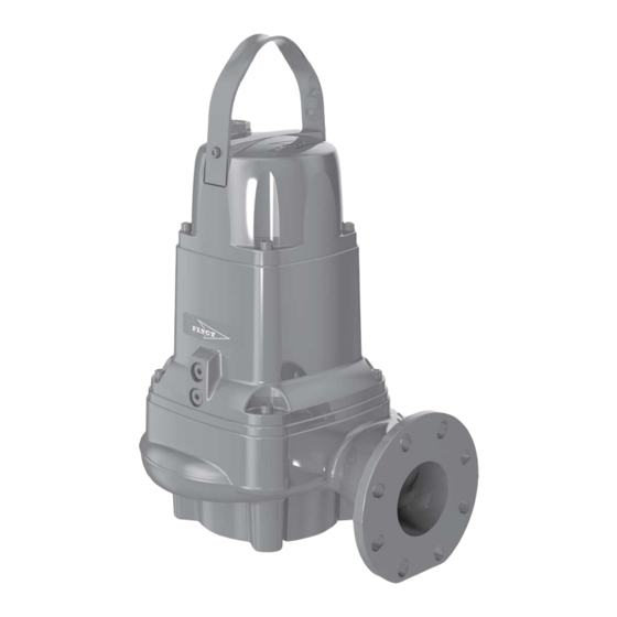
4 Product Description 4 Product Description Products included System Pump version Gateway Concertor ™ 6020.180 – Concertor ™ 6020.180 FPG 411 Concertor ™ 6020.180 FPG 412 4.1 The pump 4.1.1 Pump design The pump is designed for submersible use, and driven by a control system that is connected to a permanent-magnet synchronous motor. - Page 16 4 Product Description Illustrations Figure 1: N 6020.180 MT/100, iron Concertor ™ 6020 Installation, Operation, and Maintenance Manual...
- Page 17 4 Product Description Figure 2: N 6020.180 LT/150, aluminum Parts Position Part Insert ring with a guide pin Pump housing, without flush valve connection Seal housing cover Stator housing unit with a leakage sensor Cooling jacket Connection housing with integrated control system Lifting handle Cable entry Support bearing...
-
Page 18: The Data Plate
4 Product Description Position Part Adaptive-N impeller Gateway Pressure class, discharge connection LT/150 Low head MT/100 Medium head HT/80 High head 4.1.2 The data plate 1. Serial number, see Product denomination on page 16 2. Product number 3. Additional information 4. -
Page 19: The Gateways
4 Product Description Codes and parameters XXYYYY YYY YYY YYYY Type of Callout Number Indication Type of code Sales denomination Product code Serial number Parameter Hydraulic end Type of installation Sales code Version Production year Production cycle Running number 4.2 The gateways 4.2.1 Product design ™... -
Page 20: Parts
4 Product Description 4.2.3 Parts 1. Front connections 2. Status LEDs 3. Top connections 4. Back plane bus 5. Bottom connections 4.2.4 The data plate 1. Brand 2. Product 3. Batch number. Edition number. 4. Country of origin. Manufacturer. 5. Approvals 6. -
Page 21: Mechanical Installation
5 Mechanical Installation 5 Mechanical Installation 5.1 Precautions General precautions Before starting work, make sure that the safety instructions in the chapter Introduction and Safety on page 3 have been read and understood. Electrical precautions DANGER: Electrical Hazard Before starting work on the unit, make sure that the unit and the control panel are isolated from the power supply and cannot be energized. -
Page 22: Requirements
5 Mechanical Installation 5.2 Requirements General requirements • Use the dimensional drawing to make sure that the installation is correct. • Always remove all debris and waste materials from the sump and piping before installation. Piping requirements NOTICE: Never force piping to make a connection with a pump. 5.3 Make the mechanical installation 5.3.1 Prepare the site: new P-installation For more information, see the separate accessories documentation. -
Page 23: Install The Pump: P-Installation
5 Mechanical Installation 5.3.2 Install the pump: P-installation P Semipermanent, wet well arrangement with the pump installed on two guide bars. The connection to the discharge is automatic. 1. Install the sliding bracket unit on the pump. For more information, see the separate accessories documentation. 2. -
Page 24: Install The Pump: S-Installation
5 Mechanical Installation 4. Attach the permanent lifting device to the sump structure. 5. Secure the motor cable. Make sure that the cable cannot be sucked into the pump inlet and that it is not sharply bent or pinched. 6. Connect the motor cable according to the separate instructions. Clean all the debris from the sump before the pump is started. -
Page 25: Install The Gateway
5 Mechanical Installation Make sure that the pump cannot fall over or sink. 5. Connect the discharge line to the discharge connection. 6. Attach the permanent lifting device to the sump structure. 7. Secure the motor cable. Make sure that the cable cannot be sucked into the pump inlet and that it is not sharply bent or pinched. -
Page 26: Electrical Installation
6 Electrical Installation 6 Electrical Installation 6.1 Precautions General precautions Before starting work, make sure that the safety instructions in the chapter Introduction and Safety on page 3 have been read and understood. Electrical precautions DANGER: Electrical Hazard Before starting work on the unit, make sure that the unit and the control panel are isolated from the power supply and cannot be energized. -
Page 27: Requirements
6 Electrical Installation DANGER: Explosion/Fire Hazard Special rules apply to installations in explosive or flammable atmospheres. Do not install the product or any auxiliary equipment in an explosive zone unless it is rated explosion- proof or intrinsically-safe. If the product is EN/ATEX-, MSHA- or FM-approved, then see the specific EX information in the Safety chapter before taking any further actions. -
Page 28: Make The Electrical Connections
6 Electrical Installation Cable requirements NOTICE: Leakage into the electrical parts can cause damaged equipment or a blown fuse. Keep the cable ends dry at all times. • The cables must be in good condition, not have any sharp bends, and not be pinched. •... -
Page 29: Connect The Motor Cable To The Pump
6 Electrical Installation 6. Aluminum foil 7. Ground (earth) core with green/yellow shrink hose 8. Uncovered screen/braided wire ® Figure 3: The prepared screened SUBCAB cable 1. Peel off the outer sheath at the end of the cable. 2. Prepare the control element: a) Peel the sheath (if applicable) and the copper foil. -
Page 30: Connect The Motor Cable To Mains And To The Monitoring Equipment
6 Electrical Installation 6.3.3 Connect the motor cable to mains and to the monitoring equipment DANGER: Explosion/Fire Hazard Special rules apply to installations in explosive or flammable atmospheres. Do not install the product or any auxiliary equipment in an explosive zone unless it is rated explosion- proof or intrinsically-safe. - Page 31 6 Electrical Installation Cable Terminal External Hand-Off-Auto control Hand on: DI3 is high and DI4 is low Hand off: DI3 is low and DI4 is high Auto: DI3 is low and DI4 is low Pump run feedback Sum alarm A Sum alarm B Pump cleaning in progress Actual power...
-
Page 32: Cable Charts
6 Electrical Installation 6.4 Cable charts Connection plate 6020.180 U, V, W 1 - 15 6020.090 L1, L2, L3 (2x) 791 48 01_7 Connections Connection V1 W1 Earth/Ground continuity U V W 1 2 3 4 5 6 7 8 9 10 11 12 13 14 15 Screen as ground conductor Shrink hose GNYE... - Page 33 6 Electrical Installation 1. Screen 2. Ground (earth) 3. Functional ground 4. Leakage sensor 5. Terminal block Color code standard Code Description Brown Black White Orange Green GNYE Green-Yellow Grey Blue Yellow Concertor ™ 6020 Installation, Operation, and Maintenance Manual...
-
Page 34: Operation
7 Operation 7 Operation 7.1 Precautions Before taking the unit into operation, check the following: • All recommended safety devices are installed. • The cable and cable entry have not been damaged. • All debris and waste material has been removed. NOTICE: Never operate the pump with the discharge line blocked, or the discharge valve closed. -
Page 35: Alarm Handling
7 Operation WARNING: Crush Hazard Never put your hand into the pump housing. 2. Turn on the power supply for the system. Make sure that the external controller, the gateways, and the pump receive power. The pump runs at preset values. For more information about the operation of the system, see the User Guide. -
Page 36: Maintenance
8 Maintenance 8 Maintenance Precautions Before starting work, make sure that the safety instructions in the chapter Introduction and Safety on page 3 have been read and understood. DANGER: Crush Hazard Moving parts can entangle or crush. Always disconnect and lock out power before servicing to prevent unexpected startup. -
Page 37: Torque Values
8 Maintenance Inspect the work area before permit-required hot work WARNING: Explosion/Fire Hazard Before starting any permit-required hot work such as welding, gas cutting, grinding, or using electrical handtools, do the following: 1. Check the explosion risk. 2. Provide sufficient ventilation. Ground continuity verification A ground (earth) continuity test must always be performed after service. -
Page 38: Maintenance Intervals
8.2 Maintenance intervals Type of service Purpose Inspection interval Initial inspection A Xylem-authorized personnel checks the pump condition. From Within the first year of the results, the personnel recommends the intervals for the operation. periodical inspection and major overhaul for the installation. -
Page 39: Major Overhaul
8 Maintenance Service item Action Zinc anodes If applicable, replace the zinc anodes. Anodes are replaced when the anode mass is reduced to a selected fraction of its initial mass. The recommended interval for the selection fraction is 0.25–0.50 (25– 50%). -
Page 40: Change The Oil
8 Maintenance 3. Replace the O-ring and install the inspection plug. Tightening torque: 44 Nm (33 ft-lb). 8.4 Change the oil Item Label Description OIL OUT Oil plug for the oil drainage OIL IN Oil plug for the oil refill Figure 6: Oil plugs Empty the oil CAUTION: Compressed Gas Hazard... - Page 41 8 Maintenance 2. Put a container under the pump and turn the pump. Remove the oil plug, OIL IN, to simplify the process. Fill with oil The oil must be a medical white oil of paraffin type that fulfills FDA Sec. 172.878 (a) requirements.
- Page 42 8 Maintenance 4. Turn the pump so that OIL IN faces upwards. 5. Fill with oil. Quantity: approximately 1 L (1 quarts) 6. Refit and tighten the oil plug, OIL IN. Tightening torque: 44 Nm (33 ft-lb) Concertor ™ 6020 Installation, Operation, and Maintenance Manual...
-
Page 43: Replace The Impeller
8 Maintenance 8.5 Replace the impeller CAUTION: Cutting Hazard Worn parts can have sharp edges. Wear protective clothing. NOTICE: When laying the pump on its side, do not allow the weight of the pump to rest on any portion of the impeller. The impeller must not be allowed to make contact with the concrete floor or other hard and rough surfaces. - Page 44 8 Maintenance 2. Prepare the shaft: a) Make sure that the end of the shaft is clean and free from burrs. Polish off any flaws with a fine emery cloth. b) Coat the inner conic and the outer cylindrical surfaces of the sleeve with a thin layer of grease.
- Page 45 8 Maintenance Tightening torque: 44 Nm (33 ft-lb). 9. Tighten it a further 1/8 turn (45°). 10.Check that the impeller can rotate freely. WARNING: Crush Hazard Beware of the pinch point hazard between the rotating impeller and the guide pin. 11.Use an extended feeler gauge to make sure that the impeller clearance is 0.1–0.7 mm (0.004–0.028 in).
-
Page 46: Troubleshooting
9 Troubleshooting 9 Troubleshooting Introduction DANGER: Electrical Hazard Troubleshooting a live control panel exposes personnel to hazardous voltages. Electrical troubleshooting must be done by a qualified electrician. Follow these guidelines when troubleshooting: • Disconnect and lock out the power supply except when conducting checks that require voltage. -
Page 47: The Impeller Does Not Rotate
9 Troubleshooting 9.2 The impeller does not rotate DANGER: Crush Hazard Moving parts can entangle or crush. Always disconnect and lock out power before servicing to prevent unexpected startup. Failure to do so could result in death or serious injury. WARNING: Electrical Hazard The permanent-magnet motor generates voltage when the shaft rotates, even if power sources are disconnected. -
Page 48: The Pump Does Not Receive Commands From The Gateway
9 Troubleshooting If the problem persists, contact the local sales and service representative. Always state the product number and the serial number of your product. 9.5 The pump does not receive commands from the gateway Cause Remedy There is no communication between 1. - Page 49 9 Troubleshooting WARNING: Electrical Hazard The permanent-magnet motor generates voltage when the shaft rotates, even if power sources are disconnected. Never perform any electrical work if the shaft could rotate. NOTICE: Do NOT override the motor protection repeatedly if it has tripped. Doing so may result in equipment damage.
-
Page 50: Technical Reference
10 Technical Reference 10 Technical Reference 10.1 The pump 10.1.1 Motor data The drive unit includes a synchronous motor with IE4 equivalent efficiency. NOTICE: Do not connect a starter or a Variable Frequency Drive (VFD) to this unit. Feature Description Input frequency 50–60 Hz Supply... -
Page 51: Ip-Rating
10 Technical Reference Parameter Value Operating humidity Relative humidity, non-condensing: 90% Sunlight exposure UV-resistant Maximum altitude • With UL approval: 2000 m (6562 ft) • Without UL approval: 4000 m (13 123 ft) 10.2.3 IP-rating IP20 10.2.4 Electrical data Parameter Value Supply voltage + 24 VDC... -
Page 52: Source Code
10 Technical Reference Section Terminal Description Flygt FOP 312 interface, DeviceNet 1: Ground 2: CAN low 3: Shield 4: CAN high 5: +24 VDC RS485 Modbus slave RS485 24 VDC ±10% 24 VDC < 700 mA. Typical: 150 mA − Fuse: 1 A Potential free relay output Maximum 250 VAC, 5 A... - Page 56 For more information on how Xylem can help you, go to xyleminc.com Refer to www.xylemwatersolutions.com/contacts/ for contact details of your local sales and service representative.