Table of Contents
Advertisement
USER GUIDE AND SPECIFICATIONS
NI 6528/6529
Contents
Français
Deutsch
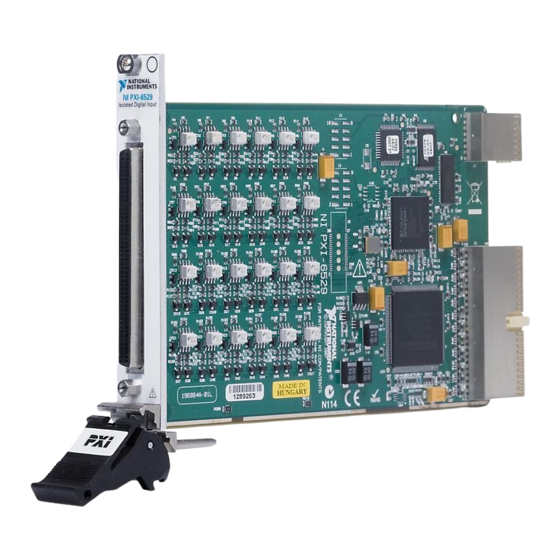
The NI PCI/PXI-6528 device provides 24 isolated input channels and
24 isolated output channels, and the NI PXI-6529 provides 48 isolated
input channels. The NI 6528/6529 features digital filtering, change
detection, and Real-Time System Integration (RTSI) capabilities. The
NI 6528 also features programmable power-up output states and a
watchdog timer. The NI 6528/6529 is ideal for high-voltage isolation
and switching in both industrial and laboratory environments.
Configuration .......................................................................................... 2
Programming Devices in Software .................................................. 3
Functional Overview............................................................................... 4
Safety Information .................................................................................. 5
Related Documentation........................................................................... 7
Features ................................................................................................... 8
Digital Filtering................................................................................ 8
Digital Filtering Example ......................................................... 9
RTSI................................................................................................. 9
Change Detection............................................................................. 10
Change Detection and RTSI ..................................................... 10
Change Detection Example ...................................................... 11
Programmable Power-Up Output States (NI 6528 Only) ................ 11
Watchdog Timer (NI 6528 Only) .................................................... 12
Watchdog Timer and RTSI....................................................... 12
Digital I/O ............................................................................................... 13
I/O Connector .................................................................................. 13
Pin Assignments .............................................................................. 13
Signal Descriptions .......................................................................... 15
ni.com/manuals
Advertisement
Table of Contents

Related Manuals for NI 6528


Summary of Contents for NI 6528
-
Page 1: Table Of Contents
Français Deutsch ni.com/manuals The NI PCI/PXI-6528 device provides 24 isolated input channels and 24 isolated output channels, and the NI PXI-6529 provides 48 isolated input channels. The NI 6528/6529 features digital filtering, change detection, and Real-Time System Integration (RTSI) capabilities. The NI 6528 also features programmable power-up output states and a watchdog timer. -
Page 2: Configuration
• Verify that you are using the correct version of NI-DAQ (NI-DAQ 7.1 or later for the NI 6528, and NI-DAQ 8.6 or later for the NI 6529). To download the most recent National Instruments drivers, go to ni.com/drivers •... -
Page 3: Programming Devices In Software
• NI PCI-6528 devices must be installed into a slot that provides 3.3 V. Check that the 3.3 V LED (reference designator DS1—located on the visible edge of the underside of the installed device) is lit. If not, check that the PC motherboard provides 3.3 V to the PCI bus. -
Page 4: Functional Overview
• NI-DAQmx examples for ANSI C are in the directory NI-DAQ\Examples\DAQmx ANSI C Dev • Traditional NI-DAQ (Legacy) examples for ANSI C are in the directory NI-DAQ\Examples\VisualC For additional examples, refer to zone.ni.com Functional Overview Figures 1 and 2 illustrate the key functional components of the NI 6528/6529 device. -
Page 5: Safety Information
If you need to clean the DIO device, use a soft, nonmetallic brush. Make sure that the DIO device is completely dry and free from contaminants before returning it to service. © National Instruments Corporation NI 6528/6529 User Guide and Specifications... - Page 6 Working voltage is the highest rms value of an AC or DC voltage that can occur across any particular insulation. MAINS is defined as a hazardous live electrical supply system that powers equipment. Suitably rated measuring circuits may be connected to the MAINS for measuring purposes. NI 6528/6529 User Guide and Specifications ni.com...
-
Page 7: Related Documentation
• DAQ Getting Started guides—These guides describes how to install the NI-DAQ software, the DAQ device, and how to confirm that the device is operating properly. • NI-DAQmx Help—This help file contains information about using NI-DAQmx to program National Instruments devices. -
Page 8: Features
Digital Filtering Use the digital filter option available on the NI 6528/6529 input lines to eliminate glitches on input data. When used with change detection, filtering can also reduce the number of changes to examine and process. -
Page 9: Digital Filtering Example
RTSI-compatible devices. Use the National Instruments RTSI cable to connect the NI PCI-6528 to other RTSI-compatible devices. The NI PXI-6528/6529 uses pins on the RTSI connector to connect the RTSI bus to the PXI trigger bus, as defined in the PXI Hardware Specification, Revision 2.1. -
Page 10: Change Detection
Change Detection and RTSI You can program the NI 6528/6529 to send a 200 ns pulse to any or all RTSI lines when a change is detected. The pulse generates when a change detection event occurs. -
Page 11: Change Detection Example
If the switch closure is noisy, enable digital filtering for this line. In this example, the NI 6528/6529 reports rising edges only on bit 1, falling edges only on bit 0, and rising and falling edges on bits 7, 6, 5, and 4. The NI 6528/6529 reports no changes for bits 3 and 2. -
Page 12: Watchdog Timer (Ni 6528 Only)
You can program the NI 6528 to send a 200 ns logic high pulse to any or all RTSI lines when the watchdog timer expires. Additionally, you can program the watchdog timer to expire when it detects either a rising or a falling edge on a single RTSI line. -
Page 13: Digital I/O
For input ports on the NI 6528/6529, connect the higher voltage to the PX.Y+ pin and the lower voltage to the PX.Y– pin. For output ports on the NI 6528, you can connect signals to the two pins of each line, regardless of which has the higher voltage. The output lines on the NI 6528 are solid-state relays and act as bi-directional switches. - Page 14 P3.0– +5 V +5 V NI 6528 (Pins 1–48) Direction Input—Ports 0, 1, and 2 (Pins 51–98) Direction Output with Readback—Ports 3, 4, and 5 NI 6529 (Pins 1–48, 51–98) Direction Input—Ports 0 through 5 Figure 4. NI 6528/6529 Pinout NI 6528/6529 User Guide and Specifications ni.com...
-
Page 15: Signal Descriptions
Refer to the Signal Descriptions section for information about the signals available on this connector. Signal Descriptions Table 3 and Table 4 list the signals and descriptions for all signals available on the NI 6528/6529 devices. Table 3. NI 6528 Signal Descriptions Signal Name Direction Description P<0..2>.<7..0>+ Input Isolated input ports <0..2>, positive terminals—Take... -
Page 16: Optically Isolated Inputs
These pins are not isolated. Optically Isolated Inputs Pins 1 through 48 on the NI 6528 and pins 1 through 48 and 51 through 98 on the NI 6529 are optically isolated input signal pins. These inputs consist of a light-emitting diode (LED), a depletion-mode MOSFET-based current limiting circuit, and digital filtering and change-detection circuitry. -
Page 17: Signal Connection Example
When the switch is open, no current flows through the load and no voltage is applied to the load or to the NI 6528/6529 device input. The digital logic of the NI 6528/6529 device then registers a logic low for the channel. -
Page 18: Solid-State Relay Outputs (Ni 6528 Only)
Solid-State Relay Outputs (NI 6528 Only) The solid-state relay (SSR) output channels on the NI 6528 device consist of an LED and two MOSFETs that are connected to form a bi-directional switch. Depending on how the load is connected to the terminals, an output can either source or sink current. -
Page 19: Using The Ni 6528 As A Ttl-Level Device
Using the NI 6528 as a TTL-Level Device Using the +5 V line from the NI 6528 device allows you to use it as a TTL-level output device with non-isolated power. Figure 8 shows a signal connection example for both sinking and sourcing current. -
Page 20: Maximum Power Ratings
This fuse is not customer replaceable. If the fuse is blown, return the device to NI for repair. The power pins, +5 V and GND, connect to the computer power supply and are Caution not isolated. -
Page 21: Isolation Circuitry
The Clare LAA125 solid-state relays provide isolation on the output for the NI 6528. Each IC has two independent solid-state relays, each of which provides isolation at each channel of output. Isolation Voltages The positive and negative (PX.Y+ and PX.Y–) terminals of each channel are... -
Page 22: Accessories
CB-50LP connector block, panel mount (777101) RTSI cable (776249) — For more information about optional equipment available from National Instruments, refer to the National Instruments catalog or visit the National Instruments Web site at ni.com NI 6528/6529 User Guide and Specifications ni.com... -
Page 23: Specifications
Specifications This section lists the specifications for the NI 6528/6529 device. These specifications are typical at 25 °C, unless otherwise noted. Power Requirement +5 VDC (±5%)........250 mA, typical (excluding the power consumed through the I/O connector) +3.3 VDC (±5%) NI 6528 ........... - Page 24 Input current ...........3.0 mA/channel, max Minimum pulse-width for change detection .......150 s Propagation delay ........65 s, typical Solid-State Relay Outputs (NI 6528 Only) Number of channels........24, each with two terminals that are isolated from other channels Relay type ..........Normally open form A solid-state...
- Page 25 (6.3 in. × 3.9 in.) Weight PCI-6528 ......... 107.7 g (3.8 oz) PXI-6528/6529........ 130.4 g (4.6 oz) Environmental The NI 6528/6529 device is intended for indoor use only. Operating Environment Ambient temperature range....0 to 55 °C (tested in accordance with IEC-60068-2-1 and IEC-60068-2-2) Relative humidity range ......
- Page 26 ICES-001: Class A emissions For the standards applied to assess the EMC of this product, refer to the Online Note Product Certification section. For EMC compliance, operate this device with shielded cables. Note NI 6528/6529 User Guide and Specifications ni.com...
- Page 27 CVI, National Instruments, NI, ni.com, and LabVIEW are trademarks of National Instruments Corporation. Refer to the Terms of Use section on ni.com/legal for more information about National Instruments trademarks. The mark LabWindows is used under a license from Microsoft Corporation.
Need help?
Do you have a question about the 6528 and is the answer not in the manual?
Questions and answers