Table of Contents
Advertisement
USER GUIDE AND SPECIFICATIONS
NI myRIO-1900
The National Instruments myRIO-1900 is a portable reconfigurable I/O (RIO) device that
students can use to design control, robotics, and mechatronics systems. This document contains
pinouts, connectivity information, dimensions, mounting instructions, and specifications for the
NI myRIO-1900.
2
1
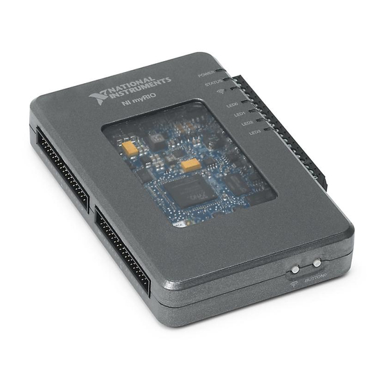
NI myRIO-1900
2
myRIO Expansion Port (MXP) Breakouts (One
Included in Kit)
3
Power Input Cable
4
USB Device Cable
5
USB Host Cable (Not Included in Kit)
Figure 1. NI myRIO-1900
3
4
1
9
6
LEDs
7
Mini System Port (MSP) Screw-Terminal
Connector
8
Audio In/Out Cables (One Included in Kit)
9
Button0
5
6
7
8
Advertisement
Table of Contents

Related Manuals for NI myRIO-1900


Summary of Contents for NI myRIO-1900
- Page 1 USER GUIDE AND SPECIFICATIONS NI myRIO-1900 The National Instruments myRIO-1900 is a portable reconfigurable I/O (RIO) device that students can use to design control, robotics, and mechatronics systems. This document contains pinouts, connectivity information, dimensions, mounting instructions, and specifications for the NI myRIO-1900.
- Page 2 The maximum length for USB cables is 2.0 m (6.6 ft), and the maximum length for signal wires is 30.0 cm (11.8 in.). Caution The mounting keyholes on the back of the NI myRIO-1900 are sensitive to electrostatic discharge (ESD). When handling the device, be careful not to touch inside the keyholes.
- Page 3 Hardware Overview The NI myRIO-1900 provides analog input (AI), analog output (AO), digital input and output (DIO), audio, and power output in a compact embedded device. The NI myRIO-1900 connects to a host computer over USB and wireless 802.11b,g,n. The following figure shows the arrangement and functions of NI myRIO-1900 components.
- Page 4 Connector Pinouts NI myRIO-1900 Expansion Port (MXP) connectors A and B carry identical sets of signals. The signals are distinguished in software by the connector name, as in ConnectorA/DIO1 . Refer to the software documentation for information about configuring ConnectorB/DIO1 and using signals.
- Page 5 DIO lines. UART.TX DGND Output UART transmit output. UART lines are electrically identical to DIO lines. DGND Reference for digital signals, +5 V, and +3.3 V. NI myRIO-1900 User Guide and Specifications | © National Instruments | 5...
- Page 6 General-purpose digital lines with Output 3.3 V output, 3.3 V/5 V-compatible input. Refer to the DIO Lines section for more information. DGND Reference for digital lines and +5 V power output. 6 | ni.com | NI myRIO-1900 User Guide and Specifications...
- Page 7 Analog Input Channels The NI myRIO-1900 has analog input channels on myRIO Expansion Port (MXP) connectors A and B, Mini System Port (MSP) connector C, and a stereo audio input connector. The analog inputs are multiplexed to a single analog-to-digital converter (ADC) that samples all channels.
- Page 8 Caution Before using headphones to listen to the audio output of the NI myRIO-1900, ensure that the audio output is at a safe level. Listening to audio signals at a high volume may result in permanent hearing loss. 8 | ni.com | NI myRIO-1900 User Guide and Specifications...
- Page 9 ±10 V Left Audio Output ±2.5 V Right Accelerometer The NI myRIO-1900 contains a three-axis accelerometer. The accelerometer samples each axis continuously and updates a readable register with the result. Refer to the Accelerometer section of the Specifications for the accelerometer sample rates.
- Page 10 Maximum Negative Reading = -2048 * 3.906 mg = -8.000 g DIO Lines The NI myRIO-1900 has 3.3 V general-purpose DIO lines on the MXP and MSP connectors. MXP connectors A and B have 16 DIO lines per connector. On the MXP connectors, each DIO line from 0 to 13 has a 40 kΩ...
- Page 11 You can add a stronger resistor to a DIO line to cause it to float in the opposite direction. UART Lines The NI myRIO-1900 has one UART receive input line and one UART transmit ouput line on each MXP connector. The UART lines are electrically identical to DIO lines 0 to 13 on the MXP connectors.
- Page 12 When the NI myRIO-1900 is in safe mode, you can communicate with it by using the UART lines on MXP connector A. You need the following items to communicate with the myRIO device over UART: •...
- Page 13 Understanding LED Indications Power LED The Power LED is lit while the NI myRIO-1900 is powered on. This LED indicates that the power supply connected to the device is adequate. Status LED The Status LED is off during normal operation. The NI myRIO-1900 runs a power-on self test (POST) when you apply power to the device.
- Page 14 104.5 mm (4.11 in.) 94.3 mm (3.71 in.) 87.5 mm (3.44 in.) 80.6 mm (3.17 in.) 73.8 mm (2.90 in.) 0.0 mm (0.0 in.) 0.0 mm 88.6 mm (0.0 in.) (3.49 in.) 14 | ni.com | NI myRIO-1900 User Guide and Specifications...
- Page 15 19 x 3.8 mm (0.15 in.) (0.94 in.) 16.4 mm (0.65 in.) 12.2 mm (0.48 in.) 0.0 mm (0.0 in.) 0.0 mm 46.0 mm (0.0 in.) (1.81 in.) Pin 1 NI myRIO-1900 User Guide and Specifications | © National Instruments | 15...
- Page 16 Mounting the NI myRIO-1900 Using the Key Holes You can use the provided key holes on NI myRIO-1900 to mount the device on a flat surface. Install the NI myRIO-1900 as shown in Figure 16. Use Unified #4 or ISO M3 screws to mount the NI myRIO-1900 using the key holes.
- Page 17 Secure the panel to the NI myRIO-1900. You must use the included 4-40 × 1/4 in. screw to attach the panel mounting kit to the NI myRIO-1900. Tighten the screw to 0.76 N · m (6.7 lb · in.) of torque. Do not exceed 0.87 N ·...
- Page 18 Fasten the panel mounting kit to the panel or wall using screws appropriate for the surface. The following figure shows the dimensions of the NI myRIO-1900 with the panel mounting kit installed. Figure 18. Dimensions of NI myRIO-1900 with Panel Mounting Kit 57.2 mm...
- Page 19 Use a cable tie to secure the power and USB cables to the panel mounting kit as shown in Figure 19. Figure 19. Securing the Power and USB Cables to the Panel Mounting Kit NI myRIO-1900 User Guide and Specifications | © National Instruments | 19...
- Page 20 Info Code ni.com/info SSDBP FPGA FPGA type ............Xilinx Z-7010 Wireless Characteristics Radio mode ............IEEE 802.11 b,g,n Frequency band..........ISM 2.4 GHz Channel width ...........20 MHz 20 | ni.com | NI myRIO-1900 User Guide and Specifications...
- Page 21 Configuration..........One stereo input consisting of two AC-coupled, single-ended channels Input impedance ........10 kΩ at DC Nominal range .......... ±2.5 V Bandwidth..........2 Hz to >20 kHz NI myRIO-1900 User Guide and Specifications | © National Instruments | 21...
- Page 22 MSP connector..........1 port of 8 DIO lines Direction control ..........Each DIO line individually programmable as input or output Logic level ............5 V compatible LVTTL input; 3.3 V LVTTL output 22 | ni.com | NI myRIO-1900 User Guide and Specifications...
- Page 23 Maximum current on each connector ..100 mA +3.3 V power output Output voltage .......... 3.0 V to 3.6 V Maximum current on each connector ..150 mA NI myRIO-1900 User Guide and Specifications | © National Instruments | 23...
- Page 24 Typical idle power consumption.......2.6 W Environmental To meet these specifications, you must operate the NI myRIO-1900 with the window facing away from the mounting surface and ensure that there is at least 1 in. of clearance in front of the window during use.
- Page 25 Online Product Certification section. Caution Using the NI myRIO-1900 in a manner not described in this document may impair the protection the NI myRIO-1900 provides. Hazardous Locations The NI myRIO-1900 is not certified for use in hazardous locations. Electromagnetic Compatibility...
- Page 26 For additional environmental information, refer to the Minimize Our Environmental Impact web page at . This page contains the environmental regulations and ni.com/environment directives with which NI complies, as well as other environmental information not included in this document. Waste Electrical and Electronic Equipment (WEEE) EU Customers At the end of the product life cycle, all products must be sent to a WEEE recycling center.
- Page 27 Canada. To reduce potential radio interference to other users, the antenna type and its gain should be so chosen that the equivalent isotropically radiated power (e.i.r.p.) is not more than that necessary for successful communication. NI myRIO-1900 User Guide and Specifications | © National Instruments | 27...
- Page 28 éventuelle pour les autres utilisateurs, le type et le gain de l’antenne doivent être choisis de manière à ce que la puissance isotrope rayonnée équivalente (p.i.r.e.) minimale nécessaire à une bonne communication soit fournie. 28 | ni.com | NI myRIO-1900 User Guide and Specifications...
- Page 29 1999/5/EC. Magyar Alulírott, National Instruments nyilatkozom, hogy a NI myRIO-1900 [Hungarian] megfelel a vonatkozó alapvetõ követelményeknek és az 1999/5/EC irányelv egyéb elõírásainak. NI myRIO-1900 User Guide and Specifications | © National Instruments | 29...
- Page 30 överensstämmelse med de väsentliga egenskapskrav och övriga relevanta bestämmelser som framgår av direktiv 1999/5/EG. Íslenska Hér með lýsir National Instruments yfir því að NI myRIO-1900 er í [Icelandic] samræmi við grunnkröfur og aðrar kröfur, sem gerðar eru í tilskipun 1999/5/EC.
- Page 31 Warranty For customers other than private individual users in the EU: The NI myRIO-1900 is warranted against defects in materials and workmanship for a period of one year from the date of shipment, as evidenced by receipts or other documentation. National Instruments will, at its option, repair or replace equipment that proves to be defective during the warranty period.
- Page 32 Refer to the NI Trademarks and Logo Guidelines at ni.com/trademarks for more information on National Instruments trademarks. Other product and company names mentioned herein are trademarks or trade names of their respective companies. For patents covering National Instruments products/technology, refer to the appropriate location: Help»Patents in your software, the patents.txt file on your media, or the...
Need help?
Do you have a question about the myRIO-1900 and is the answer not in the manual?
Questions and answers