
Subscribe to Our Youtube Channel
Related Manuals for hilscher COMX Series


Summary of Contents for hilscher COMX Series
- Page 1 Design Guide COMX Communication Modules Hilscher Gesellschaft für Systemautomation mbH www.hilscher.com DOC100901DG18EN | Revision 18 | English | 2013-12 | Released | Public...
-
Page 2: Table Of Contents
3.1.9 Signals of the Host Interface – Serial Dual-Port Memory Mode ............58 Fieldbus Interface.........................59 LEDs.............................60 Diagnostic Interface ........................62 3.4.1 Diagnostic Interface RS232C ......................62 COMX Communication Modules | Design Guide DOC100901DG18EN | Revision 18 | English | 2013-12 | Released | Public © Hilscher, 2002-2013... -
Page 3: Introduction
4.1.18 COMX 100CN-DP ........................... 74 4.1.19 COMX 100CN-RE ........................... 74 Appendix ...............................75 List of Tables..........................75 List of Figures..........................77 Contacts ............................78 COMX Communication Modules | Design Guide DOC100901DG18EN | Revision 18 | English | 2013-12 | Released | Public © Hilscher, 2002-2013... -
Page 4: Introduction
COM Modules are the previous generation of communication modules. The COM Modules are de- scribed in an own manual. The following two tables give a comparison of both COM and COMX Modules. COMX Communication Modules | Design Guide DOC100901DG18EN | Revision 18 | English | 2013-12 | Released | Public © Hilscher, 2002-2013... -
Page 5: Comparison Comx And Com Modules
Slave (third generation) supported VARAN Client (Slave) supported Table 2: Comparison of supported protocols for COM and COMX COMX Communication Modules | Design Guide DOC100901DG18EN | Revision 18 | English | 2013-12 | Released | Public © Hilscher, 2002-2013... -
Page 6: List Of Revisions
Update of section “SYNC Signals” 4.1.11 Added new EMV data section for COMX 51CA-RE Table 3: List of Revisions COMX Communication Modules | Design Guide DOC100901DG18EN | Revision 18 | English | 2013-12 | Released | Public © Hilscher, 2002-2013... -
Page 7: Technical Features
COMX 10 and COMX 51 modules offer a serial dual-port memory mode as interface to the host CA and CN Types of COMX Modules For the COMX family, Hilscher offers modules with angled and without fieldbus connectors: COMX 10CN and COMX 100CN COMX Modules without fieldbus respectively Ethernet connector ... - Page 8 Generally the firmware and the configuration data are stored permanently in FLASH memory by loading the data through the dual-port memory. Figure 1: Block Diagram of the COMX Modules COMX Communication Modules | Design Guide DOC100901DG18EN | Revision 18 | English | 2013-12 | Released | Public © Hilscher, 2002-2013...
-
Page 9: Module Names
COMX-CA-DPS COMX 100CA-DP COMX-CN-DPS COMX 100CN-DP COMX 10CA-DPS COMX 10CN-DPS Table 4: comX Modules – Old and new Names COMX Communication Modules | Design Guide DOC100901DG18EN | Revision 18 | English | 2013-12 | Released | Public © Hilscher, 2002-2013... -
Page 10: References To Documents
Hilscher Gesellschaft für Systemautomation mbH: Getting Started Guide, Serial Dual-Port Memory Interface with netX, Revision 1, English, 2012 Hilscher Gesellschaft für Systemautomation mbH: Technical Data Reference Guide, netX 10, Revision 0.9, English, 2011-12 Hilscher Gesellschaft für Systemautomation mbH: Technical Data Reference Guide, netX 51/52, Revision 2, English, 2012-13 Hilscher Gesellschaft für Systemautomation mbH: EtherCAT V4 Protocol API, Revision 3,... -
Page 11: Legal Notes
There is no entitlement to revisions of delivered documents. The manual delivered with the product applies. Hilscher Gesellschaft für Systemautomation mbH is not liable under any circumstances for direct, indirect, incidental or follow-on damage or loss of earnings resulting from the use of the information contained in this publication. -
Page 12: Exclusion Of Liability
1.7.3 Exclusion of Liability The software was produced and tested with utmost care by Hilscher Gesellschaft für Systemauto- mation mbH and is made available as is. No warranty can be assumed for the performance and flawlessness of the software for all usage conditions and cases and for the results produced when utilized by the user. -
Page 13: Design-In - Mechanical Aspects
(depends on loaded firmware) COMX 100CN-RE Realtime Ethernet Master or Slave (depends on loaded firmware) Table 6: Available comX Modules COMX Communication Modules | Design Guide DOC100901DG18EN | Revision 18 | English | 2013-12 | Released | Public © Hilscher, 2002-2013... - Page 14 CN Types Figure 2: COMX CA Type - Connector X1 Figure 3: COMX CN Type - Connectors X1 and X2 COMX Communication Modules | Design Guide DOC100901DG18EN | Revision 18 | English | 2013-12 | Released | Public © Hilscher, 2002-2013...
-
Page 15: Mechanical Dimensions
CN type, the parts defining the height of these modules are the DC/DC converter and the trans- former. In order to assure the long-term availability of the modules, Hilscher claims the right to perform a redesign if necessary due to changes in availability of components and to exchange these compo- nents by similar ones which might differ in their dimensions. - Page 16 M0900164 Mechanical dimension of cover and connector of COMX 100CA-XXX (fieldbus) M1100052 Mechanical dimension of cover and rotary switch of COMX 50-CA-CCS COMX Communication Modules | Design Guide DOC100901DG18EN | Revision 18 | English | 2013-12 | Released | Public © Hilscher, 2002-2013...
- Page 17 Design-In - Mechanical Aspects 17/78 COMX Communication Modules | Design Guide DOC100901DG18EN | Revision 18 | English | 2013-12 | Released | Public © Hilscher, 2002-2013...
- Page 18 Design-In - Mechanical Aspects 18/78 COMX Communication Modules | Design Guide DOC100901DG18EN | Revision 18 | English | 2013-12 | Released | Public © Hilscher, 2002-2013...
- Page 19 Design-In - Mechanical Aspects 19/78 COMX Communication Modules | Design Guide DOC100901DG18EN | Revision 18 | English | 2013-12 | Released | Public © Hilscher, 2002-2013...
- Page 20 Design-In - Mechanical Aspects 20/78 COMX Communication Modules | Design Guide DOC100901DG18EN | Revision 18 | English | 2013-12 | Released | Public © Hilscher, 2002-2013...
- Page 21 Design-In - Mechanical Aspects 21/78 COMX Communication Modules | Design Guide DOC100901DG18EN | Revision 18 | English | 2013-12 | Released | Public © Hilscher, 2002-2013...
- Page 22 Design-In - Mechanical Aspects 22/78 COMX Communication Modules | Design Guide DOC100901DG18EN | Revision 18 | English | 2013-12 | Released | Public © Hilscher, 2002-2013...
- Page 23 Design-In - Mechanical Aspects 23/78 COMX Communication Modules | Design Guide DOC100901DG18EN | Revision 18 | English | 2013-12 | Released | Public © Hilscher, 2002-2013...
- Page 24 Design-In - Mechanical Aspects 24/78 COMX Communication Modules | Design Guide DOC100901DG18EN | Revision 18 | English | 2013-12 | Released | Public © Hilscher, 2002-2013...
-
Page 25: Type Of Connector
Please use the same type of connector on the motherboard if you have chosen the COMX CN type module. COMX Communication Modules | Design Guide DOC100901DG18EN | Revision 18 | English | 2013-12 | Released | Public © Hilscher, 2002-2013... - Page 26 Design-In - Mechanical Aspects 26/78 COMX Communication Modules | Design Guide DOC100901DG18EN | Revision 18 | English | 2013-12 | Released | Public © Hilscher, 2002-2013...
-
Page 27: Storage And Contact Reliability Of Host-Side Connector
Hilscher only uses highly reliable connectors in the comX modules. The supplier of the connector warrants a minimum expected storage time of 5 years without any loss of spring tension when the connectors have been mounted. -
Page 28: Mounting Of Comx Modules
'normal' via (drill 0,3 mm) to feed the signals to the bottom side. Figure 4: How to layout the Signals at the Connectors X1 and X2 COMX Communication Modules | Design Guide DOC100901DG18EN | Revision 18 | English | 2013-12 | Released | Public © Hilscher, 2002-2013... - Page 29 The drawing for an assembled bolt is shown on the following drawing: M0200402 Mechanical dimension how to assemble COM-CA-XXX on the mother board COMX Communication Modules | Design Guide DOC100901DG18EN | Revision 18 | English | 2013-12 | Released | Public © Hilscher, 2002-2013...
- Page 30 Design-In - Mechanical Aspects 30/78 COMX Communication Modules | Design Guide DOC100901DG18EN | Revision 18 | English | 2013-12 | Released | Public © Hilscher, 2002-2013...
- Page 31 Design-In - Mechanical Aspects 31/78 COMX Communication Modules | Design Guide DOC100901DG18EN | Revision 18 | English | 2013-12 | Released | Public © Hilscher, 2002-2013...
- Page 32 Design-In - Mechanical Aspects 32/78 COMX Communication Modules | Design Guide DOC100901DG18EN | Revision 18 | English | 2013-12 | Released | Public © Hilscher, 2002-2013...
- Page 33 Design-In - Mechanical Aspects 33/78 COMX Communication Modules | Design Guide DOC100901DG18EN | Revision 18 | English | 2013-12 | Released | Public © Hilscher, 2002-2013...
-
Page 34: Material Recommendation For The Faceplate
Example: For station address 12 set the left address switch to 1 and the right address switch to 2. COMX Communication Modules | Design Guide DOC100901DG18EN | Revision 18 | English | 2013-12 | Released | Public © Hilscher, 2002-2013... -
Page 35: Canopen Slave
Example: For MAC ID 12 set the left address switch to 1 and the right address switch to 2. COMX Communication Modules | Design Guide DOC100901DG18EN | Revision 18 | English | 2013-12 | Released | Public © Hilscher, 2002-2013... -
Page 36: Cc-Link Slave
1 … 63 1 … 62 1 … 61 Table 14: Value Range for Station Address depending on Number of Stations COMX Communication Modules | Design Guide DOC100901DG18EN | Revision 18 | English | 2013-12 | Released | Public © Hilscher, 2002-2013... -
Page 37: Comx 50Ca-Ccs
1 … 63 1 … 62 1 … 61 Table 16: Value Range for Station Address depending on Number of Stations COMX Communication Modules | Design Guide DOC100901DG18EN | Revision 18 | English | 2013-12 | Released | Public © Hilscher, 2002-2013... - Page 38 … Invalid, Error Invalid, Error Table 17: Settings for CC-Link Slave Address with the Address Switch of COMX 50CA-CCS COMX Communication Modules | Design Guide DOC100901DG18EN | Revision 18 | English | 2013-12 | Released | Public © Hilscher, 2002-2013...
-
Page 39: Design-In - Electrical Aspects
So not all address lines need to be used. Unused address lines may be equipped with a pull-down resistor of 560 Ω. COMX Communication Modules | Design Guide DOC100901DG18EN | Revision 18 | English | 2013-12 | Released | Public © Hilscher, 2002-2013... -
Page 40: Host Interface: Parallel Or Serial Dual-Port Memory Mode
Important: Never drive the host interface mode signal (DPM_DIRQn). Instead, operation with pull- down and pull-up resistors is recommended. COMX Communication Modules | Design Guide DOC100901DG18EN | Revision 18 | English | 2013-12 | Released | Public © Hilscher, 2002-2013... -
Page 41: Comx Pinning Of The System Bus Connector X1 - Parallel Mode
Host mode selection LVTTL Input Table 20: COMX Pinning of the System Bus Connector X1- Parallel DPM Mode (Part 1) COMX Communication Modules | Design Guide DOC100901DG18EN | Revision 18 | English | 2013-12 | Released | Public © Hilscher, 2002-2013... - Page 42 SYNC0 and SYNC1 are available on COMX 100CA-RE, COMX 100CN-RE, COMX 51CA-RE and COMX 50CA-REFO only. Table 22: Notes for COMX Pinning of the System Bus Connector X1 COMX Communication Modules | Design Guide DOC100901DG18EN | Revision 18 | English | 2013-12 | Released | Public © Hilscher, 2002-2013...
-
Page 43: Comx Pinning Of The System Bus Connector X1 - Serial Mode
Note 3 Table 23: COMX Pinning of the System Bus Connector X1- Serial DPM Mode COMX 10/COMX 51 (Part 1) COMX Communication Modules | Design Guide DOC100901DG18EN | Revision 18 | English | 2013-12 | Released | Public © Hilscher, 2002-2013... -
Page 44: Pad Type Explanation
Output driver can source / sink 9 mA Output driver can source / sink 18 mA XTAL Crystal input or output COMX Communication Modules | Design Guide DOC100901DG18EN | Revision 18 | English | 2013-12 | Released | Public © Hilscher, 2002-2013... - Page 45 (TDOTAC33NN06, (TDBIAPCUNLP36C) TDOPAC33NN09) TDOTAC33NN09) (TDIPAC33D) (TDIPAC33N) (TDIPAC33U) IOZUS9 (TDIPAC33DS) (TDIPAC33US) (TDBIAC33WN09S) Figure 6: Schematic View of netX Pad Types COMX Communication Modules | Design Guide DOC100901DG18EN | Revision 18 | English | 2013-12 | Released | Public © Hilscher, 2002-2013...
-
Page 46: Signal Overview And Pinning Of The Fieldbus Connector X2 On Comx Cn
LVTTL Signals can only be used without the hardware interface on the COMX. Ask for special customer ver- sion. Table 28: Notes for Fieldbus Connector X2 for CC-Link Slave COMX Communication Modules | Design Guide DOC100901DG18EN | Revision 18 | English | 2013-12 | Released | Public © Hilscher, 2002-2013... -
Page 47: Fieldbus Connector X2 For Canopen-Master/-Slave
LVTTL Signals can only be used without the hardware interface on the COMX. Ask for special customer ver- sion. Green LED for COMX 100CN-CO Table 30: Notes for Fieldbus Connector X2 for CANopen-Master/-Slave COMX Communication Modules | Design Guide DOC100901DG18EN | Revision 18 | English | 2013-12 | Released | Public © Hilscher, 2002-2013... -
Page 48: Fieldbus Connector X2 For Devicenet-Master/-Slave
LVTTL Signals can only be used without the hardware interface on the COMX. Ask for special customer ver- sion. Table 32: Notes for Fieldbus Connector X2 for DeviceNet-Master/-Slave COMX Communication Modules | Design Guide DOC100901DG18EN | Revision 18 | English | 2013-12 | Released | Public © Hilscher, 2002-2013... -
Page 49: Fieldbus Connector X2 For Profibus-Master/-Slave
LVTTL Signals can only be used without the hardware interface on the COMX. Ask for special customer ver- sion. Green LED for COMX 100CN-DP Table 34: Notes for Fieldbus Connector X2 for PROFIBUS-Master/-Slave COMX Communication Modules | Design Guide DOC100901DG18EN | Revision 18 | English | 2013-12 | Released | Public © Hilscher, 2002-2013... -
Page 50: Fieldbus Connector X2 For Real Time Ethernet
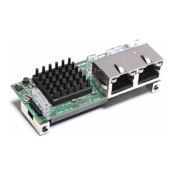
The Pin layout is designed to fit for a RJ45 connector with integrated transformers, LEDs and ter- mination. Suggested part: 203313, ERNI or J8064D628ANL, Pulse COMX Communication Modules | Design Guide DOC100901DG18EN | Revision 18 | English | 2013-12 | Released | Public © Hilscher, 2002-2013... - Page 51 Figure 7: Ethernet Connection COMX-CN-RE The following figure shows the ERNI connector 203313 as an example: Figure 8: Ethernet Connector Example (ERNI 203313) COMX Communication Modules | Design Guide DOC100901DG18EN | Revision 18 | English | 2013-12 | Released | Public © Hilscher, 2002-2013...
-
Page 52: Common Signals Of The Host Interface
Please refer to the special documents for the basic description of the data model and communica- tion methods with devices based on the netX. COMX Communication Modules | Design Guide DOC100901DG18EN | Revision 18 | English | 2013-12 | Released | Public © Hilscher, 2002-2013... -
Page 53: Address Bus And Data Bus
10 kΩ pull-up resistor for COMX 100 and COMX 50CA-CCS, a 50 kΩ pull-up resistor for COMX 50CA-REFO. COMX Communication Modules | Design Guide DOC100901DG18EN | Revision 18 | English | 2013-12 | Released | Public © Hilscher, 2002-2013... -
Page 54: Busy Line To The Host System
(no burst access). Moreover there must be a recovery time during two accesses. For further details please refer the following timing diagrams. COMX Communication Modules | Design Guide DOC100901DG18EN | Revision 18 | English | 2013-12 | Released | Public © Hilscher, 2002-2013... -
Page 55: Timing Diagram Parallel Dual-Port Memory Interface
The following diagram shows the timing for dual-port memory write access. Figure 10: COMX Timing Diagram for Write Access Description and values are on the next page. COMX Communication Modules | Design Guide DOC100901DG18EN | Revision 18 | English | 2013-12 | Released | Public © Hilscher, 2002-2013... - Page 56 Note 3: DPM_BHEn is only used for 16 bit interface. COMX Communication Modules | Design Guide DOC100901DG18EN | Revision 18 | English | 2013-12 | Released | Public © Hilscher, 2002-2013...
-
Page 57: Integration Of Comx Module Into A Host System
D[15:8] 0 (low) low byte access D[7:0] no access, illegal Table 38: Function Table of Decode Logic COMX Communication Modules | Design Guide DOC100901DG18EN | Revision 18 | English | 2013-12 | Released | Public © Hilscher, 2002-2013... -
Page 58: Signals Of The Host Interface - Serial Dual-Port Memory Mode
For information about the software implementation and the protocol see section Host Software Im- plementation and section Serial DPM Protocol Description in [4]. COMX Communication Modules | Design Guide DOC100901DG18EN | Revision 18 | English | 2013-12 | Released | Public © Hilscher, 2002-2013... -
Page 59: Fieldbus Interface
Design-In - Electrical Aspects 59/78 Fieldbus Interface Figure 13: Fieldbus Interface Connections COMX Communication Modules | Design Guide DOC100901DG18EN | Revision 18 | English | 2013-12 | Released | Public © Hilscher, 2002-2013... -
Page 60: Leds
100CN-DN, COMX 100CN-DP. This is the new design for all COMX modules which is compatible to the COM-CN modules. Figure 14: Example how to connect the LEDs COMX CN Fieldbus COMX Communication Modules | Design Guide DOC100901DG18EN | Revision 18 | English | 2013-12 | Released | Public © Hilscher, 2002-2013... - Page 61 Figure 15: Example how to connect the LEDs COMX 100CN-RE The meaning of the LED is documented in [2] (english language) and in [3] (german language). COMX Communication Modules | Design Guide DOC100901DG18EN | Revision 18 | English | 2013-12 | Released | Public © Hilscher, 2002-2013...
-
Page 62: Diagnostic Interface
The module has not integrated drivers. Figure 16: RS232C Interface Circuit for the Diagnostic Interface The diagnostic interface is galvanically coupled (not potential free). COMX Communication Modules | Design Guide DOC100901DG18EN | Revision 18 | English | 2013-12 | Released | Public © Hilscher, 2002-2013... -
Page 63: Diagnostic Interface Usb
COMX 100CA-DP COMX 100CN-DP COMX 100CA-RE COMX 100CN-RE Table 39: Hardware Revision of COMX Modules with new USB Interface COMX Communication Modules | Design Guide DOC100901DG18EN | Revision 18 | English | 2013-12 | Released | Public © Hilscher, 2002-2013... - Page 64 Hardware Revision of COMX Modules with new USB Interface on page 63. Figure 18: USB Interface Circuit Modification for the Diagnostic Interface COMX Communication Modules | Design Guide DOC100901DG18EN | Revision 18 | English | 2013-12 | Released | Public © Hilscher, 2002-2013...
- Page 65 COMX 100CN-DP COMX 50CA-CCS COMX 100CA-RE COMX 100CN-RE Table 40: Hardware Revision of COMX Modules with old USB Interface COMX Communication Modules | Design Guide DOC100901DG18EN | Revision 18 | English | 2013-12 | Released | Public © Hilscher, 2002-2013...
-
Page 66: Sync Signals
III Slave CON_CLK DIV_CLK 3.0.10.0 Configurable Output Output Table 41: Meaning of the SYNC Signals for each Protocol COMX Communication Modules | Design Guide DOC100901DG18EN | Revision 18 | English | 2013-12 | Released | Public © Hilscher, 2002-2013... -
Page 67: Technical Data
40 x 70 x 21.5 mm for further extension Weight 35 gr. 40 gr. Table 44: Technical Data – Mechanical Dimensions COMX Communication Modules | Design Guide DOC100901DG18EN | Revision 18 | English | 2013-12 | Released | Public © Hilscher, 2002-2013... -
Page 68: Product Tests
+ 2 kV Programmable Controllers EN 61000-4-5 Surge Communication lines (shielded) 1 kV Table 47: Product Tests COMX 10CA-COS – Immunity COMX Communication Modules | Design Guide DOC100901DG18EN | Revision 18 | English | 2013-12 | Released | Public © Hilscher, 2002-2013... -
Page 69: Comx 10Cn-Cos
+ 2.5 kV Programmable Controllers EN 61000-4-5 Surge Communication lines (shielded) 1 kV Table 50: Product Tests COMX 10CN-DPS – Immunity COMX Communication Modules | Design Guide DOC100901DG18EN | Revision 18 | English | 2013-12 | Released | Public © Hilscher, 2002-2013... -
Page 70: Comx 10Ca-Dns
EN 61131-2 (2008-04)+A11, A12 Communication lines (shielded) + 2 kV Programmable Controllers Table 53: Product Tests COMX 50CA-REFO – Immunity COMX Communication Modules | Design Guide DOC100901DG18EN | Revision 18 | English | 2013-12 | Released | Public © Hilscher, 2002-2013... -
Page 71: Comx 50Ca-Ccs
Surge Communication lines (shielded) 1 kV 2 Ohm / 18 μF Table 56: Product Tests COMX 100CA-CO – Immunity COMX Communication Modules | Design Guide DOC100901DG18EN | Revision 18 | English | 2013-12 | Released | Public © Hilscher, 2002-2013... -
Page 72: Comx 100Ca-Dn
Programmable Controllers EN 61000-4-5 Surge Communication lines (shielded) 1 kV Table 59: Product Tests COMX 100CA-RE Rev.8 – Immunity COMX Communication Modules | Design Guide DOC100901DG18EN | Revision 18 | English | 2013-12 | Released | Public © Hilscher, 2002-2013... -
Page 73: Comx 100Cn-Co
(unshielded) (24 V---PE, GND---PE) DeviceNet 24 V power supply 0,6 kV (unshielded) (24 V---GND) Table 61: Product Tests COMX 100CN-DN – Immunity COMX Communication Modules | Design Guide DOC100901DG18EN | Revision 18 | English | 2013-12 | Released | Public © Hilscher, 2002-2013... -
Page 74: Comx 100Cn-Dp
Surge Communication lines (shielded) 1 kV 2 Ohm / 18 μF Table 63: Product Tests COMX 100CN-RE - Immunity COMX Communication Modules | Design Guide DOC100901DG18EN | Revision 18 | English | 2013-12 | Released | Public © Hilscher, 2002-2013... -
Page 75: Appendix
Table 62: Product Tests COMX 100CN-DP – Immunity....................74 Table 63: Product Tests COMX 100CN-RE - Immunity ....................74 COMX Communication Modules | Design Guide DOC100901DG18EN | Revision 18 | English | 2013-12 | Released | Public © Hilscher, 2002-2013... - Page 76 Appendix 76/78 COMX Communication Modules | Design Guide DOC100901DG18EN | Revision 18 | English | 2013-12 | Released | Public © Hilscher, 2002-2013...
-
Page 77: List Of Figures
Figure 17: USB Interface Circuit for the Diagnostic Interface .................... 63 Figure 18: USB Interface Circuit Modification for the Diagnostic Interface ................ 64 COMX Communication Modules | Design Guide DOC100901DG18EN | Revision 18 | English | 2013-12 | Released | Public © Hilscher, 2002-2013... -
Page 78: Contacts
+49 (0) 6190 9907-50 E-Mail: info@hilscher.com Support Phone: +49 (0) 6190 9907-99 E-Mail: de.support@hilscher.com Subsidiaries China Japan Hilscher Systemautomation (Shanghai) Co. Ltd. Hilscher Japan KK 200010 Shanghai Tokyo, 160-0022 Phone: +86 (0) 21-6355-5161 Phone: +81 (0) 3-5362-0521 E-Mail: info@hilscher.cn E-Mail: info@hilscher.jp...
Need help?
Do you have a question about the COMX Series and is the answer not in the manual?
Questions and answers