Table of Contents
Advertisement
Advertisement
Chapters
Table of Contents

Related Manuals for Multiaqua MAC120 Series


Summary of Contents for Multiaqua MAC120 Series
-
Page 2: Table Of Contents
Table of Contents (Hydronic) Page About Us System Modeling Software Multi-Zoning and Energy Cost Features and Benefits Water Products Overview DX Products Overview Accessory Products Overview Equipment Sound Data MAC120 Air-Cooled Chiller Nomenclature Breakdown Guide Specifications Product Specifications Capacities Installation and Operating Manual Wiring Diagrams Certified Drawing MAC036,048 and 060 Air Cooled Chiller... - Page 3 Table of Contents (Hydronic Continued) Page MCCW (Ceiling Concealed) 2-Pipe Chilled and Hot Water. 4 to 5 Tons Nomenclature Breakdown Guide Specifications Product Specifications Chilled Water Capacities Hot Water Capacities CFM and Glycol Adjustments Capacity Adjustment Factors Installation and Operating Manual Wiring Diagrams Certified Drawing MHWW (Hi-Wall) 2-Pipe Chilled and Hot Water.
- Page 4 Table of Contents (Direct Expansion) Page MHCCX (Ceiling Concealed) DX with Electric Heat. 1 to 3 Tons Nomenclature Breakdown Guide Specifications Product Specifications Capacities CFM Adjustments Installation and Operating Manual Wiring Diagrams Certified Drawing MCCX (Ceiling Concealed) DX Only. 4 to 5 Tons Nomenclature Breakdown Guide Specifications Product Specifications...
- Page 5 Table of Contents (Accessories) Accessories Page Storage Tanks Expansion Tank and Air Scoop Liquid Solution Bypass Valve Liquid Solution Control Valves Condensate Pump Control Thermostats Wye Strainer Circulating Pumps (1,1.5 & 2 HP) Circulating Pump Curve (1,1.5 & 2 HP) Circulating Pumps (.5 HP) Circulating Pump Curve (.5 HP) Ceiling Concealed Enclosures...
-
Page 6: About Us
Experience The Future At Multiaqua, we invite you to come experience the future of air conditioning and see why more and more companies are discovering the new standard of air conditioning excellence. And by combining cost effectiveness, innovation and quality, Multiaqua will continue to provide air conditioning products that will be the most sought after in the world. -
Page 7: System Modeling Software
Sample Design Shown Introducing System Modeling Software Multiaqua has teamed up with HVAC Solutions and would like to introduce the newest version of the HSS Software. This software will contain a selection model that includes Mutiaqua’s Air Cooled Chillers, Fan Coils and Air Handling Units. - Page 9 Ductless and Ducted Hydronic Air Conditioning & Heating Systems. FOR MULTIZONING FACILITIES • Zoning saves energy • Better Control of Humidity • Separate Climate in each Room 1. More Energy Efficient Thru Zoned Comfort Cooling. 2. Zoning Allows For Diversity. 3.
-
Page 10: Water Products Overview
Water Product Overview Page 44 Page 9 MAC036, 048 & 060 Air Cooled Chiller MAC120 Air Cooled Chiller • 3, 4 & 5 Ton Air Cooled Chiller • 10 Ton Air Cooled Chiller • Copeland Scroll Compressor Technology • Copeland Scroll Compressor Technology •... -
Page 11: Dx Products Overview
DX Product Overview DX Fan Coils are Compatible with R410a Refrigerant and are 13 SEER Compatible All DX Coils come Shipped From the Factory with a TXV Installed. MHCCX (Ceiling Concealed) DX 2-Pipe MHNCCX (Ceiling Concealed) DX 4-Pipe With or Without Electric Heat with Hot Water •... - Page 12 Accessories Overview Page 385 Page 387 Page 388 Storage Tanks Expansion Tank & Air Scoop Liquid Solution Bypass Valve 20 & 42 Gallon Page 389 Page 395 Page 391 Wye Strainer Condensate Pump Motorized Valves 2 & 3-Way Page 392 Page 396 Page 398 Thermostats...
- Page 13 January 2008 Multiaqua Equipment Sound Levels The following will detail the “Sound Levels” of the Multiaqua equipment line. Air Cooled Chillers MAC 036, 048, 060 Chillers: 69 dbs (A) MAC120 Chillers: 75 dbs (A) Hi-Wall Fan Coils MHWX-09 / MHWW-09: DX and chilled water Hi-Wall fan coils: 42 dbs (A).
-
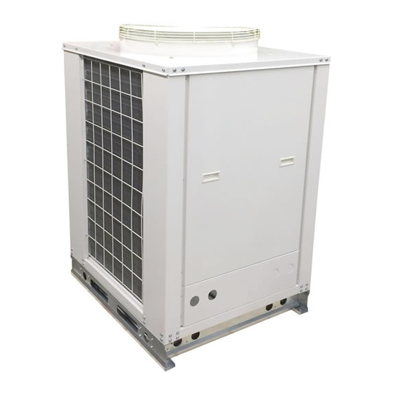
Page 14: Mac120 Air-Cooled Chiller
MAC120 Air-Cooled Chiller Air-Cooled Chillers for Global Residential and Light Commercial MicroClimates... -
Page 15: Nomenclature Breakdown
MAC120 NOMENCLATURE BREAKDOWN MAC120 - XX - X - R407 10-Ton Accessory Air-Cooled Chiller Options N= No Options L= Low Ambient Kit Voltage 01 = 208/230-1-50/60 02 = 208/230-3-50/60 03 = 380/460-3-50/60 Available Model Numbers MAC120-01-N-R407 MAC120-01-L-R407 MAC120-02-N-R407 MAC120-02-L-R407 MAC120-03-N-R407 MAC120-03-L-R407... -
Page 16: Guide Specifications
MAC120-03-N-407, MAC120-03-L-407 Part 1-General 1.01 System Description Multiaqua air-cooled liquid chillers are designed using scroll compressors and low sound condenser fans. 1.02 Quality Assurance A. Certified in accordance with U.L. Standard 95, latest version (U.S.A.) B. Construction shall comply with ASHRAE 15 Safety Code, NEC and ASME applicable codes. (U.S.A. - Page 17 F. Pump: 1. Unit shall be capable of incorporating a field installed chilled liquid solution pump. (Space restricted) 2. Unit shall have provisions to allow for chilled liquid solution piping to the exterior of the cabinet. G. Evaporator: 1. Evaporator shall have two independent refrigerant circuits. 2.
-
Page 18: Product Specifications
Internal Pressure Drop 18 ft of head Multiaqua chillers are designed to operate exclusively with R407c refrigerant in a self-contained, pre-charged refrigerant system. Do not access the closed refrigerant circuit for any reason other than after-sale, after installation component replacement. Routine maintenance and service is to be performed by qualified personnel only. - Page 19 *Use Propylene Glycol Only Important If the outside temperature is expected to fall below freezing (32°F) in the area the Multiaqua chiller is to be installed; the installer must take the following precautions. Failure to do so will void the warranty.
-
Page 20: Capacities
MAC120 Cooling Performance Data MAC120 CAPACITIES with 0% Glycol ENTERING AIR TEMPERATURE (°F) LWT (°F) TONS GPM TONS GPM TONS GPM TONS GPM TONS GPM 28.8 28.8 28.8 28.8 28.8 10.1 10.4 10.0 11.3 10.9 10.5 10.4 10.3 12.3 11.8 11.4 11.2 11.1... - Page 21 MAC120 Cooling Performance Data MAC120 CAPACITIES with 30% Glycol ENTERING AIR TEMPERATURE (°F) LWT (°F) TONS GPM TONS GPM TONS GPM TONS GPM TONS GPM 28.8 28.8 28.8 28.8 28.8 10.1 11.0 10.6 10.2 10.1 10.0 11.9 11.5 11.1 10.9 10.8 MAC120 CAPACITIES with 40% Glycol ENTERING AIR TEMPERATURE (°F)
- Page 23 Table of Contents Page Introduction System Description & Sequence of Operation Electrical & Physical Data Description of Electrical Controls Chiller Controls Sequence of Operation Refrigeration System Operation Description of Refrigeration Components Piping System Components Layout & Design Banked Chiller Configuration Installation Notes Propylene Glycol Content Expansion Tank...
-
Page 24: Introduction
The Multiaqua Chiller System is not only unique in its application flexibility; it is unique in superior quality, rated capacities and rugged durability. When installed in accordance with these instructions the system will deliver years of trouble free service. -
Page 25: System Description & Sequence Of Operation
America) Manual “J”, Refer to the appendix A-2, Multi-Zone Systems. ACCA’s Internet address is http://www.acca.org/ Because of diversity a Multiaqua Chiller can serve more total air handler tonnage than chiller capacity. A 10-ton chiller may be delivering chilled liquid solution to 15 or more tons of air handler capacity. Because of cooling load diversity, the building does not need equal amounts of cooling in each area at the same time. -
Page 26: Electrical & Physical Data
ELECTRICAL AND PHYSICAL DATA The information contained in this manual has been prepared to assist in the proper installation, operation and maintenance of the chiller. Improper installation, or installation not made in accordance with these instructions can result in unsatisfactory operation and/or dangerous conditions and can cause the related warranty not to apply. - Page 27 Consult local building codes or ordinances for special installation requirements. When selecting a site to locate the chiller, consider the following: • A minimum clearance of 60” on the service access front, 12” on the rear air inlet and a 60” fan discharge clearance.
-
Page 28: Description Of Electrical Controls
Description of Electrical Controls Control Transformer: The control transformer is rated at 24 vac, 40 va (1.6 amps @ 24vac) The pump bypass timer is a 24 vac, 3-wire control. Pump Bypass Timer: When energized the timer will bypass the flow switch for 10 seconds (by creating a circuit to the pump relay), energizing the pump relay, allowing the pump to operate long enough to close the flow switch. - Page 29 Description of Electrical Controls (continued) The low-pressure switch is an automatic reset control Low Pressure Switch: that senses compressor suction line pressure. It opens at 40 PSIG and closes at 80 PSIG. Flow Switch: The flow switch senses liquid solution flow. The paddle of the switch is inserted through a fitting into the pump discharge line.
-
Page 30: Chiller Controls Sequence Of Operation
Chiller Controls Sequence of Operation When powered up, the Multiaqua chiller system energizes the control transformer creating 24 vac control voltage. First the pump bypass timer is energized and temporarily bypasses the flow switch, energizing the pump relay. The pump then starts to move liquid solution through the piping system (in a properly filled and air purged system). The movement of liquid solution from the pump discharge keeps the flow switch closed. -
Page 31: Refrigeration System Operation
10 °F below condensing temperature. Description Of Refrigerant Components Scroll Compressor: All Multiaqua chillers feature Scroll compressors. Scroll technology ensures reliable high performance at a low sound level over a wide range of operating conditions. - Page 32 The counter flow design and fluid turbulence ensures maximum heat exchange at minimal pressure drop. Thermal Expansion Valve: Multiaqua chillers are equipped with Thermal Expansion valves. The valves feature a liquid charged sensing bulb for consistent superheat at various load conditions.
-
Page 33: Piping System Components
Piping System Components Supply Storage Tank: The supply storage tank must be used in the system with less than 25 gallons of liquid solution. The tank prevents rapid cycling of the compressors and acts as a reserve for chilled liquid solution. Supply storage tank must be insulated in the field. -
Page 34: Layout & Design
Piping resistance or pressure drop is measured in feet of head. A foot of head is the amount of pressure drop imposed in lifting liquid solution one foot. Pumps in the Multiaqua system are designed to move rated liquid solution flow (see... -
Page 35: Banked Chiller Configuration
Banked Chiller Configuration Notes: Installing Multiaqua chillers in parallel is recommended. -
Page 36: Installation Notes
Installation Notes: Piping such as PEX,steel, copper or PVC can be used with the Multiaqua system. Check local building codes for material conformation. Care must be taken when using PVC as the presence of propylene glycol may destroy plastics. Pressure drop data for the selected piping material is readily available and should be used. Should the Multiaqua chiller be installed using existing steel (ferrous metal) piping system, dielectric fittings must be used at the chiller and air handler. -
Page 37: Propylene Glycol Content
Liquid solution expansion and contraction within the closed system must be compensated for with an expansion tank. The expansion tank used with the Multiaqua system, is a steel tank with a rubber bladder attached to it internally. There is air pressure on one side of the rubber bladder that keeps the bladder pushed against the sides of the tank before the system is filled with liquid solution (illustration above). -
Page 38: Filling The System With Propylene Glycol
Filling System with Liquid Solution and Coolant (Propylene Glycol) Before filling system with Propylene Glycol and water, pressure test the piping system with compressed air. Testing should be done at a maximum of 50 psi.The system should hold air pressure for a minimum of one hour with no leakage. - Page 39 MAC120-3 Ladder Wiring Diagram 380/460-3-50/60...
- Page 40 MAC120-3 Wiring Diagram 380/460-3-50/60 MULTIAQUA 380/460-3-50/60 COMP CON1` LPS1 COMP CON2 HPS1 TIMER1 REL 1 REL 2 NOTE 1 LPS2 HPS2 DTC 1 DTC 2 24 vac 24 vac MAC120-03 380/460-3-50/60 LEGEND: COMPRESSOR CONTACTOR TITLE NOTES: FACTORY WIRING FLOW SWITCH 1.PUMP STARTER RELAY...
- Page 41 MAC120-3-L with Low Ambient Kit Wiring Diagram 380/460/-3-50/60 MULTIAQUA 380/460-3-50/60 COMP CON1` LPS1 COMP CON2 HPS1 TIMER1 REL 1 REL 2 NOTE 1 FAN CYCLE PRESSURE SWITCH LPS2 HPS2 FAN CYCLE DTC 1 DTC 2 PRESSURE SWITCH 24 vac 24 vac...
- Page 42 MAC120-2 Ladder Wiring Diagram 208/230-3-50/60...
- Page 43 MAC120-2 Wiring Diagram 208/230-3-50/60...
- Page 44 MAC120-2-L with Low Ambient Kit Wiring Diagram 208/230-3-50/60...
- Page 45 MAC120-1 Ladder Wiring Diagram 208/230-1-50/60...
- Page 46 MAC120-1 Wiring Diagram 208/230-1-50/60...
- Page 47 MAC120-1-L with Low Ambient Kit Wiring Diagram 208/230-1-50/60...
- Page 48 MAC120 CERTIFIED DRAWING...
- Page 49 MAC036,048 & 060 Air-Cooled Chiller Air-Cooled Chillers for Global Residential and Light Commercial MicroClimates...
-
Page 50: Nomenclature Breakdown
MAC036,048 & 060 NOMENCLATURE BREAKDOWN MACXXX - XX - X Accessory Air-Cooled Chiller Options 036= 36,0000 BTUH N= No Options 048= 48,0000 BTUH L= Low Ambient Kit 060= 60,0000 BTUH Voltage 01 = 208/230-1-50/60 02 = 208/230-3-50/60 03 = 380/460-3-50/60 Available Model Numbers MAC036-01-N MAC048-01-N... -
Page 51: Guide Specifications
MAC060-01-N-407, MAC060-01-L-407, MAC060-02-N-407, MAC060-02-L-407, Part 1-General 1.01 System Description Multiaqua air-cooled liquid chillers are designed using scroll compressors, low sound condenser fans and high efficiency pumps. 1.02 Quality Assurance A. Certified in accordance with U.L. Standard 95, latest version (U.S.A.) B. - Page 52 F. Pump: 1. Circulating pump shall be stainless steel with high efficiency enclosed motor. 2. Unit shall have chilled liquid solution piping to the exterior of the cabinet. G. Evaporator: 1. Evaporator shall have one independent refrigerant circuit and one liquid solution circuit. 2.
-
Page 53: Product Specifications
1.68 ft of head 1.85 ft of head Multiaqua chillers are designed to operate exclusively with R407c refrigerant in a self-contained, pre-charged refrigerant system. Do not access the closed refrigerant circuit for any reason other than after-sale, after installation component replacement. Routine maintenance and service is to be performed by qualified personnel only. - Page 54 Use Propylene Glycol Only Important If the outside temperature is expected to fall below freezing (32°F) in the area the Multiaqua chiller is to be installed; the installer must take the following precautions. Failure to do so will void the warranty.
-
Page 55: Capacities
MAC036 Cooling Performance Data MAC036 CAPACITIES with 0% Glycol ENTERING AIR TEMPERATURE (°F) LWT (°F) TONS GPM TONS GPM TONS GPM TONS GPM TONS GPM 1.70 1.60 1.50 1.40 1.30 2.30 2.20 2.10 2.10 2.00 2.60 2.50 2.40 2.40 2.30 2.90 2.80 2.70... - Page 56 MAC036 Cooling Performance Data MAC036 CAPACITIES with 30% Glycol ENTERING AIR TEMPERATURE (°F) LWT (°F) TONS GPM TONS GPM TONS GPM TONS GPM TONS GPM 1.67 1.57 1.47 1.37 1.27 2.25 2.16 2.06 2.06 1.96 2.55 2.45 2.35 2.35 2.25 2.84 2.74 2.65...
- Page 57 MAC048 Cooling Performance Data MAC048 CAPACITIES with 0% Glycol ENTERING AIR TEMPERATURE (°F) LWT (°F) TONS GPM TONS GPM TONS GPM TONS GPM TONS GPM 2.70 2.50 2.40 2.30 2.30 3.30 3.10 3.00 2.90 2.90 3.60 3.40 3.30 3.20 3.10 3.90 3.70 3.60...
- Page 58 MAC048 Cooling Performance Data MAC048 CAPACITIES with 30% Glycol ENTERING AIR TEMPERATURE (°F) LWT (°F) TONS GPM TONS GPM TONS GPM TONS GPM TONS GPM 2.65 2.45 2.35 2.25 2.25 3.23 3.04 2.94 2.84 2.84 3.53 3.33 3.23 3.14 3.04 3.82 3.63 3.53...
- Page 59 MAC060 Cooling Performance Data MAC060 CAPACITIES with 0% Glycol ENTERING AIR TEMPERATURE (°F) LWT (°F) TONS GPM TONS GPM TONS GPM TONS GPM TONS GPM 3.90 3.70 3.60 3.50 3.50 4.50 4.30 4.20 4.10 4.10 4.80 4.60 4.50 4.30 4.40 5.10 4.90 4.80...
- Page 60 MAC060 Cooling Performance Data MAC060 CAPACITIES with 30% Glycol ENTERING AIR TEMPERATURE (°F) LWT (°F) TONS GPM TONS GPM TONS GPM TONS GPM TONS GPM 3.82 3.63 3.53 3.43 3.43 4.41 4.21 4.12 4.02 4.02 4.70 4.51 4.41 4.21 4.31 5.00 4.80 4.70...
- Page 61 MAC 036, 048 & 060 Chiller Pump Curve Pump Model Numbers SSP-1 = 208/230-1-50/60 SSP-2 = 208/230/460-3-50/60 0.5 Horsepower...
- Page 63 Table of Contents Page Introduction System Description & Sequence of Operation Electrical & Physical Data Description of Electrical Controls Chiller Controls Sequence of Operation Refrigeration System Operation Description of Refrigeration Components Piping System Components Layout & Design Banked Chiller Configuration Installation Notes Propylene Glycol Content Expansion Tank...
-
Page 64: Introduction
The Multiaqua Chiller System is not only unique in its application flexibility; it is unique in superior quality, rated capacities and rugged durability. When installed in accordance with these instructions the system will deliver years of trouble free service. -
Page 65: System Description & Sequence Of Operation
America) Manual “J”, Refer to the appendix A-2, Multi-Zone Systems. ACCA’s Internet address is http://www.acca.org/ Because of diversity a Multiaqua Chiller can serve more total air handler tonnage than chiller capacity. For example, a 5-ton chiller may be delivering chilled liquid solution to 7 or more tons of air handler capacity. -
Page 66: Electrical & Physical Data
ELECTRICAL AND PHYSICAL DATA The information contained in this manual has been prepared to assist in the proper installation, operation and maintenance of the chiller. Improper installation, or installation not made in accordance with these instructions can result in unsatisfactory operation and/or dangerous conditions and can cause the related warranty not to apply. - Page 67 Consult local building codes or ordinances for special installation requirements. When selecting a site to locate the chiller, consider the following: • A minimum clearance of 60” on the front fan discharge, 12” on the rear air inlet and a 24” clearance is required on the service side.
-
Page 68: Description Of Electrical Controls
Description of Electrical Controls Control Transformer: The control transformer is rated at 24 vac, 40 va (1.6 amps @ 24vac) The pump bypass timer is a 24 vac, 3-wire control. Pump Bypass Timer: When energized the timer will bypass the flow switch for 10 seconds (by creating a circuit to the pump relay), energizing the pump relay, allowing the pump to operate long enough to close the flow switch. - Page 69 Description of Electrical Controls (continued) The low-pressure switch is an automatic reset control Low Pressure Switch: that senses compressor suction line pressure. It opens at 40 PSIG and closes at 80 PSIG. Flow Switch: The flow switch senses liquid solution flow. The paddle of the switch is inserted through a fitting into the pump discharge line.
-
Page 70: Chiller Controls Sequence Of Operation
Chiller Controls Sequence of Operation When powered up the Multiaqua chiller system energizes the control transformer creating 24 vac control voltage. First the pump bypass timer is energized and temporarily bypasses the flow switch, energizing the pump relay. The pump then starts to move liquid solution through the piping system (in a properly filled and air purged system). -
Page 71: Refrigeration System Operation
10°F below condensing temperature. Description Of Refrigerant Components Scroll Compressor: All Multiaqua chillers feature Scroll compressors. Scroll technology ensures reliable high performance at a low sound level over a wide range of operating conditions. - Page 72 The counter flow design and fluid turbulence ensures maximum heat exchange at minimal pressure drop. Thermal Expansion Valve: Multiaqua chillers are equipped with Thermal Expansion valves. The valves feature a liquid charged sensing bulb for consistent superheat at various load conditions.
-
Page 73: Piping System Components
Piping System Components Supply Storage Tank: The supply storage tank must be used in the system with less than 25 gallons of liquid solution. The tank prevents rapid cycling of the compressors and acts as a reserve for chilled liquid solution. Supply storage tank must be insulated in the field. -
Page 74: Layout & Design
Pump capacities in gallons per minute and pressure drop (feet of head) are listed in table 1. Banked Chiller Configuration Notes: Installing Multiaqua chillers in parallel is recommended. - Page 75 Piping resistance or pressure drop is measured in feet of head. A foot of head is the amount of pressure drop imposed in lifting liquid solution one foot. Pumps in the Multiaqua system are designed to move rated liquid solution flow...
-
Page 76: Installation Notes
Installation Notes: Piping such as PEX, steel, copper or PVC can be used with the Multiaqua system. Check local building codes for material conformation. Care must be taken when using PVC as the presence of propylene glycol may destroy plastics. Pressure drop data for the selected piping material is readily available and should be used. Should the Multiaqua chiller be installed using existing steel (ferrous metal) piping system, dielectric fittings must be used at the chiller and air handler. -
Page 77: Propylene Glycol Content
Liquid solution expansion and contraction within the closed system must be compensated for with an expansion tank. The expansion tank used with the Multiaqua system, is a steel tank with a rubber bladder attached to it internally. There is air pressure on one side of the rubber bladder that keeps the bladder pushed against the sides of the tank before the system is filled with liquid solution (illustration above). -
Page 78: Air Elimination
Filling System with Liquid Solution and Coolant (Propylene Glycol) Concentrations of Propylene Glycol in excess of 50% will destroy o-rings in fittings and pump. Water should be added to the system first or a liquid solution diluted Propylene Glycol mix. Before filling system with Propylene Glycol and water, pressure test the piping system with compressed air. -
Page 79: Wiring Diagrams
MAC060-3 Ladder Wiring Diagram 380/460-3-50/60... - Page 80 MAC060-3 Wiring Diagram 380/460-3-50/60...
- Page 81 MAC060-3-L with Low Ambient Kit Wiring Diagram 380/460-3-50/60...
- Page 82 MAC036, 048 & 060-2 Ladder Wiring Diagram 208/230-3-50/60...
- Page 83 MAC036, 048 & 060-2 Wiring Diagram 208/230-3-50/60...
- Page 84 MAC036, 048 & 060-2-L with Low Ambient Kit Wiring Diagram 208/230-3-50/60...
- Page 85 MAC036, 048 & 060-1 Ladder Wiring Diagram 208/230-1-50/60...
- Page 86 MAC036, 048 & 060-1 Wiring Diagram 208/230-1-50/60...
- Page 87 MAC036, 048 & 060-1-L with Low Ambient Kit Wiring Diagram 208/230-1-50/60...
- Page 88 MAC036, 048 & 060 CERTIFIED DRAWING...
- Page 89 MHCCW Chilled Water Ceiling Concealed With or Without Electric Heat 2-Pipe Heat / Cool Fan Coil 12,000 - 36,000 BTUH...
-
Page 90: Nomenclature Breakdown
MHCCW NOMENCLATURE BREAKDOWN 2-Pipe Heat/Cool Ceiling Concealed Fan Coil with Electric Heat MHCCW XX - XX - XX Voltage "See Notes" 00= 208/230-1-50/60 120-1-60 2-Pipe Heat/Cool w/ Electric Heat Electric Heat 00= 0 KW 02 =2KW "See Note 2 & 3" 03= 3 KW 05= 5 KW 06= 6 KW... -
Page 91: Guide Specifications
MHCCW12 Part 1-General 1.01 System Description Multiaqua Chilled Water Fan Coils are manufactured with heavy gauge galvanized steel to resist corrosion. 1.02 Quality Assurance A. Certified in accordance with U.L. Standard 95, latest version (U.S.A.) B. Manufactured in a facility registered to ISO 9002, Manufacturing Quality Standard. - Page 92 G. Electric Heat: 1. Electric Heaters shall be of the rod and disk type. 2. Shall be protected by safeties. Part 3-Controls and Safeties 3.01 Controls A. Fan coils shall be completely factory wired and tested. B. All components shall be wired to an internal terminal block to allow for a field installed thermostat and or Fan speed control.
-
Page 93: Product Specifications
MHCCW Product Specifications Physical Data Coil Copper Water Model Height Width Depth Weight Water Drain Rows Diameter Outlet Number (in) (in) (in) (lbs) Inlet (in) (in) (in) (in) MHCCW04 10.25 37.72 21.65 66.0 2-14 MHCCW06 10.25 37.72 21.65 68.2 3-14 MHCCW08 10.25 37.72... - Page 94 MHCCW Chilled Water Performance Data MHCCW04 COOLING CAPACITIES ENTERING AIR TEMPERATURE (°F) NOMINAL PRESSURE (°F) DROP (ft) 80° D.B. / 67° W.B. 75° D.B. / 63° W.B. 11.8 15.7 12.0 13.4 10.2 13.4 10.2 14.3 11.0 10.7 11.5 15.1 11.5 14.7 10.1 10.1...
- Page 95 MHCCW Chilled Water Performance Data MHCCW06 COOLING CAPACITIES ENTERING AIR TEMPERATURE (°F) NOMINAL PRESSURE (°F) DROP (ft) 80° D.B. / 67° W.B. 75° D.B. / 63° W.B. 18.5 14.1 13.4 11.7 12.3 20.4 15.6 14.1 12.3 10.2 21.6 16.5 14.5 12.6 22.4 17.1...
- Page 96 MHCCW Chilled Water Performance Data MHCCW08 COOLING CAPACITIES ENTERING AIR TEMPERATURE (°F) NOMINAL PRESSURE (°F) DROP (ft) 80° D.B. / 67° W.B. 75° D.B. / 63° W.B. 22.7 17.3 17.5 15.4 15.1 11.5 25.9 19.7 18.6 16.3 12.9 21.4 19.5 17.0 11.2 29.4...
- Page 97 MHCCW Chilled Water Performance Data MHCCW10 COOLING CAPACITIES ENTERING AIR TEMPERATURE (°F) NOMINAL PRESSURE (°F) DROP (ft) 80° D.B. / 67° W.B. 75° D.B. / 63° W.B. 28.8 22.0 21.9 19.3 14.4 11.0 31.8 24.3 20.1 12.7 1000 33.9 25.9 10.5 23.8 20.8...
- Page 98 MHCCW Chilled Water Performance Data MHCCW12 COOLING CAPACITIES ENTERING AIR TEMPERATURE (°F) NOMINAL PRESSURE (°F) DROP (ft) 80° D.B. / 67° W.B. 75° D.B. / 63° W.B. 32.3 24.7 25.4 22.4 16.2 12.4 36.1 27.6 26.8 23.5 14.4 11.0 1200 38.9 29.7 12.0...
-
Page 99: Hot Water Capacities
MHCCW Hot Water Performance Data MHCCW-04-00 HOT WATER CAPACITIES ENTERING NOMINAL ENTERING WATER TEMPERATURE (°F) AIR (°F) 100° 110° 120° 130° 140° 150° 160° 170° 180° 190° 200° 13.0 15.6 18.1 20.7 23.3 25.9 28.5 31.1 33.7 36.3 38.9 13.6 16.3 19.0 21.7... - Page 100 MHCCW Hot Water Performance Data MHCCW-06-00 HOT WATER CAPACITIES ENTERING NOMINAL ENTERING WATER TEMPERATURE (°F) AIR (°F) 100° 110° 120° 130° 140° 150° 160° 170° 180° 190° 200° 22.6 27.1 31.7 36.2 40.7 45.2 49.8 54.3 58.8 63.3 67.9 23.6 28.3 33.1 37.8...
- Page 101 MHCCW Hot Water Performance Data MHCCW-08-00 HOT WATER CAPACITIES ENTERING NOMINAL ENTERING WATER TEMPERATURE (°F) AIR (°F) 100° 110° 120° 130° 140° 150° 160° 170° 180° 190° 200° 25.2 30.2 35.3 40.3 45.3 50.4 55.4 60.4 65.5 70.5 75.6 26.4 31.6 36.9 42.2...
- Page 102 MHCCW Hot Water Performance Data MHCCW-10-00 HEATING CAPACITIES ENTERING NOMINAL ENTERING WATER TEMPERATURE (°F) AIR (°F) 100° 110° 120° 130° 140° 150° 160° 170° 180° 190° 200° 32.1 38.5 44.9 51.3 57.7 64.2 70.6 77.0 83.4 89.8 96.2 33.5 40.2 46.9 53.6 60.3...
- Page 104 MHCCW Hot Water Performance Data MHCCW-12-00 HOT WATER CAPACITIES ENTERING NOMINAL ENTERING WATER TEMPERATURE (°F) AIR (°F) 100° 110° 120° 130° 140° 150° 160° 170° 180° 190° 200° 38.9 46.7 54.5 62.3 70.1 77.9 85.7 93.5 101.2 109.0 116.8 40.6 48.7 56.8 65.0...
- Page 105 MHCCW Electric Heat Performance Data Model Nominal Electric Number Heat BTUH MHCCW04-00 MHCCW04-03 10,200 MHCCW04-05 17,000 MHCCW04-06 20,500 MHCCW04-08 27,300 MHCCW06-00 MHCCW06-03 10,200 MHCCW06-05 17,000 MHCCW06-06 20,500 MHCCW06-08 27,300 MHCCW08-00 MHCCW08-03 10,200 MHCCW08-05 17,000 MHCCW08-06 20,500 MHCCW08-08 27,300 MHCCW10-00 1000 MHCCW10-03 1000 10,200...
-
Page 106: Cfm And Glycol Adjustments
MHCCW CFM and Glycol Adjustments CFM vs. External Static Pressure Table External Static Pressure Model Number 0.00 0.05 0.10 0.15 0.20 0.25 0.30 MHCCW04 MHCCW06 MHCCW08 MHCCW10 1145 1110 1075 1035 MHCCW12 1480 1445 1405 1365 1325 1280 1235 Example: MHCCW04 @ 0.20 ESP produces 325 cfm. -
Page 107: Capacity Adjustment Factors
MHCCW Capacity Adjustment Factors CAPACITY CORRECTION FACTORS MHCCW04 MHCCW06 MHCCW08 MHCCW10 MHCCW12 MODEL # 0.79 0.75 0.82 0.78 0.85 0.82 0.88 0.86 0.90 0.89 0.94 0.93 1.00 1.00 0.90 0.89 0.92 0.91 0.94 0.93 0.95 0.94 0.80 0.77 0.96 0.95 0.82 0.79 0.98... -
Page 109: Installation And Operating Manual
The enclosure assembly Read the entire contents of this manual can be ordered separately or field fabricated before beginning installation. Multiaqua by the installing contractor. See figure 2 for assumes no responsibility for equipment enclosure part numbers, dimensions and installed contradictory to any code weights. - Page 110 INSTALLATION & OPERATING INSTRUCTIONS MHCCW Fan Coils 1- 3 Tons FAN COIL DIMENSIONS Fan Coil Model Number MHCCW04-XX 37.72 34.56 31.41 10.23 5.51 21.65 MHCCW06-XX 37.72 34.56 31.41 10.23 5.51 21.65 MHCCW08-XX 37.72 34.56 31.41 10.23 5.51 21.65 MHCCW10-XX 43.70 40.55 37.40 10.23...
- Page 111 INSTALLATION & OPERATING MANUAL MHCCW Fan Coils 1- 3 Tons -------- CAUTION ------- Care must be taken when handling sheet metal. Sheet metal parts have sharp edges and could cause injury. INSTRUCTIONS FOR CONVERTING COIL HAND OF CONNECTION Figure 4 &...
- Page 112 INSTALLATION & OPERATING MANUAL MHCCW Fan Coils 1- 3 Tons INSTRUCTIONS FOR INSTALLING FAN COIL UNIT INTO ENCLOSURE ASSEMBLY 1. Remove the ten screws that attach the electrical assembly to the fan coil unit. Do not separate the electrical assembly from the Figure 7 blower assembly.
- Page 113 INSTALLATION & OPERATING MANUAL MHCCW Fan Coils 1- 3 Tons 4. Align the fan coil mounting bolts up with the four mounting notches provided in the coil assembly top. Secure the coil assembly to the enclosure with two mounting bolts per side. Ensure that the coil assembly is level in both directions to allow proper drainage and operation.
- Page 114 INSTALLATION & OPERATING MANUAL MHCCW Fan Coils 1- 3 Tons ELECTRICAL & CONDENSATE DRAIN 8. There are four termination points for the electrical wiring. There are two on each side of the electrical box. See pages 113,114 &115 for electrical drawings. Wiring must be installed according Optional Return to prevailing codes and regulations.
- Page 115 INSTALLATION & OPERATION MANUAL MHCCW Fan Coils 1-3 Tons RETURN AND SUPPLY AIR CONNECTIONS 10. When mounting the service access panel, louvered or non-louvered, the installing contractor must provide a frame in order to connect the enclosure assembly to the service access panel. This is required to obtain an airtight seal for the return air.
- Page 116 INSTALLATION & OPERATION MANUAL MHCCW Fan Coils 1-3 Tons SERVICE ACCESS PANEL DIMENSIONS Louvered & Non-Louvered Panel Model Number Coil Size (in) (in) (in) MAP468L(NL) 43.25 27.5 MAP468L(NL) 43.25 27.5 MAP468L(NL) 43.25 27.5 MAP10L (NL) 49.25 27.5 MAP12L (NL) 55.25 27.5 Figure 17 (typ)
- Page 117 INSTALLATION & OPERATION MANUAL MHCCW Fan Coils 1-3 Tons 12. The fan coil enclosure assembly has a supply air duct flange to allow the attachment of ductwork. Ensure when attaching ductwork to the flange that the screws are at least one and half inches away from the front of the enclosure.
- Page 118 INSTALLATION & OPERATION MANUAL MHCCW Fan Coils 1-3 Tons MAITENANCE and/or replacements in the event the unit fails to operate or is being serviced. If fuses are used, ensure 1. Air Filter(s): that the replacement fuses are of the Filters are an essential part of the same size and type as the ones you quality of air that is provided to the are replacing.
- Page 119 MHCCW Without Electric Heat Wiring Diagram 208/230-1-50/60...
- Page 120 MHCCW With Electric Heat Wiring Diagram 208/230/-1-50/60...
- Page 121 MHCCW Without Electric Heat Wiring Diagram 120-1-50/60...
-
Page 122: Certified Drawing
MHCCW CERTIFIED DRAWING... - Page 123 MHNCCW Chilled/Hot Water Ceiling Concealed 4-Pipe Heat / Cool Fan Coil 12,000 - 36,000 BTUH...
-
Page 124: Nomenclature Breakdown
MHNCCW NOMENCLATURE BREAKDOWN 4-Pipe Heat/Cool Ceiling Concealed Fan Coil MHNCCW- XX - XX 4-Pipe Heat/Cool Voltage 01= 208/230-1-50/60 03= 120-1-50/60 Nominal Tons 04 = 1 Ton 06 = 1.5 Ton 08 = 2 Ton 10 = 2.5 Ton 12 = 3 Ton Available Model Numbers MHNCCW-04-01 MHNCCW-04-03... -
Page 125: Guide Specifications
MHNCCW12 Part 1-General 1.01 System Description Multiaqua Chilled Water Fan Coils are manufactured with heavy gauge galvanized steel to resist corrosion. 1.02 Quality Assurance A. Certified in accordance with U.L. Standard 95, latest version (U.S.A.) B. Manufactured in a facility registered to ISO 9002, Manufacturing Quality Standard. - Page 126 Part 3-Controls and Safeties 3.01 Controls A. Fan coils shall be completely factory wired and tested. B. All components shall be wired to an internal terminal block to allow for a field installed thermostat and or fan speed control. C. Controls shall include the following components. 24vac transformer.
-
Page 127: Product Specifications
MHNCCW Product Specifications Physical Data Cooling Heating Copper Water Water Height Length Depth Weight Drain Model Number Rows Rows Diameter Inlet Outlet (in) (in) (in) (lbs) (in) (in) (in) (in) MHNCCW04-01(03) 37.72 21.65 66.0 2-14 2-14 MHNCCW06-01(03) 37.72 21.65 68.2 3-14 2-14 MHNCCW08-01(03) - Page 128 MHNCCW Chilled Water Performance Data MHNCCW04 COOLING CAPACITIES All capacities are based on nominal CFM PRESSURE ENTERING AIR TEMPERATURE (°F) NOMINAL (°F) DROP(ft) 80° D.B. / 67° W.B. 75° D.B. / 63° W.B. 11.8 15.7 12.0 13.4 10.2 13.4 10.2 14.3 11.0 10.7...
- Page 129 MHNCCW Chilled Water Performance Data MHNCCW06 COOLING CAPACITIES All capacities are based on nominal CFM PRESSURE ENTERING AIR TEMPERATURE (°F) NOMINAL (°F) DROP(ft) 80° D.B. / 67° W.B. 75° D.B. / 63° W.B. 18.5 14.1 13.4 11.7 12.3 20.4 15.6 14.1 12.3 10.2...
- Page 130 MHNCCW Chilled Water Performance Data MHNCCW08 COOLING CAPACITIES All capacities are based on nominal CFM PRESSURE ENTERING AIR TEMPERATURE (°F) NOMINAL (°F) DROP(ft) 80° D.B. / 67° W.B. 75° D.B. / 63° W.B. 22.7 17.3 17.5 15.4 15.1 11.5 25.9 19.7 18.6 16.3...
- Page 131 MHNCCW Chilled Water Performance Data MHNCCW10 COOLING CAPACITIES All capacities are based on nominal CFM PRESSURE ENTERING AIR TEMPERATURE (°F) NOMINAL (°F) DROP(ft) 80° D.B. / 67° W.B. 75° D.B. / 63° W.B. 28.8 22.0 21.9 19.3 14.4 11.0 31.8 24.3 20.1 12.7...
- Page 132 MHNCCW Chilled Water Performance Data MHNCCW12 COOLING CAPACITIES All capacities are based on nominal CFM PRESSURE ENTERING AIR TEMPERATURE (°F) NOMINAL (°F) DROP(ft) 80° D.B. / 67° W.B. 75° D.B. / 63° W.B. 32.3 24.7 25.4 22.4 16.2 12.4 36.1 27.6 26.8 23.5...
- Page 133 MHNCCW Hot Water Performance Data MHNCCW-04 HEATING CAPACITIES ENTERING NOMINAL ENTERING WATER TEMPERATURE (°F) AIR (°F) 100° 110° 120° 130° 140° 150° 160° 170° 180° 190° 200° 11.2 13.8 16.4 19.0 21.6 24.2 26.8 29.4 32.0 34.6 37.2 13.4 16.0 18.6 21.2 23.8...
- Page 134 MHNCCW Hot Water Performance Data MHNCCW-06 HEATING CAPACITIES ENTERING NOMINAL ENTERING WATER TEMPERATURE (°F) AIR (°F) 100° 110° 120° 130° 140° 150° 160° 170° 180° 190° 200° 13.1 17.6 22.1 26.6 31.1 35.6 40.1 44.6 49.1 53.6 58.1 17.5 21.7 25.9 30.1 34.3...
- Page 135 MHNCCW Hot Water Performance Data MHNCCW-08 HEATING CAPACITIES ENTERING NOMINAL ENTERING WATER TEMPERATURE (°F) AIR (°F) 100° 110° 120° 130° 140° 150° 160° 170° 180° 190° 200° 16.8 20.5 24.1 27.7 31.4 35.0 39.0 42.4 46.5 49.7 53.3 19.2 22.8 26.4 30.0 34.7...
- Page 136 MHNCCW Hot Water Performance Data MHNCCW-10 HEATING CAPACITIES ENTERING NOMINAL ENTERING WATER TEMPERATURE (°F) AIR (°F) 100° 110° 120° 130° 140° 150° 160° 170° 180° 190° 200° 19.5 23.7 28.0 32.3 36.5 40.7 45.2 49.2 53.9 57.7 62.0 1000 23.5 27.8 32.2 36.6...
- Page 137 MHNCCW Hot Water Performance Data MHNCCW-12 HEATING CAPACITIES ENTERING NOMINAL ENTERING WATER TEMPERATURE (°F) AIR (°F) 100° 110° 120° 130° 140° 150° 160° 170° 180° 190° 200° 20.0 24.8 29.6 34.4 39.2 44.0 49.0 53.6 58.7 63.2 68.0 1200 23.8 28.6 33.4 38.2...
-
Page 138: Cfm And Glycol Adjustments
MHNCCW CFM and Glycol Adjustments Nominal CFM vs. External Static Pressure Table Hi Speed Model Number 0.05 0.15 0.25 MHNCCW04-xx MHNCCW06-xx MHNCCW08-xx MHNCCW10-xx MHNCCW12-xx 1228 1194 1160 1126 1088 1050 Example: MHNCCW08 @ 0.15 ESP produces 700 cfm. Locate 700 cfm (for the MHNCCW08) on the Capacity Adjustment Factors on page 133. (TC =.98 & SC = .98) Multiply the stated chilled water capacity for the MHCCW08 on page 124 or the hot water capacity on page 129 by the adjustment factors to achieve the capacity adjustment. -
Page 139: Capacity Adjustment Factors
MHNCCW Capacity Adjustment Factors COOLING CAPACITY CORRECTION FACTORS MHNCCW04 MHNCCW06 MHNCCW08 MHNCCW10 MHNCCW12 MODEL # 0.88 0.86 0.90 0.89 0.94 0.93 1.00 1.00 0.89 0.88 0.91 0.90 0.93 0.92 0.95 0.94 0.97 0.96 0.89 0.87 0.98 0.97 0.91 0.89 1.00 1.00 0.93 0.91... -
Page 141: Installation And Operating Manual
The enclosure assembly Read the entire contents of this manual can be ordered separately or field fabricated before beginning installation. Multiaqua by the installing contractor. See figure 2 for assumes no responsibility for equipment enclosure part numbers, dimensions and installed contradictory to any code weights. - Page 142 INSTALLATION & OPERATING INSTRUCTIONS MHNCCW Fan Coils 1- 3 Tons FAN COIL DIMENSIONS Fan Coil Model Number MHNCCW04 37.72 34.56 31.41 10.00 5.51 21.65 MHNCCW06 37.72 34.56 31.41 10.00 5.51 21.65 MHNCCW08 37.72 34.56 31.41 10.00 5.51 21.65 MHNCCW10 43.70 40.55 37.40 10.00...
- Page 143 INSTALLATION & OPERATING MANUAL MHNCCW Fan Coils 1- 3 Tons -------- CAUTION ------- Care must be taken when handling sheet metal. Sheet metal parts have sharp edges and could cause injury. INSTRUCTIONS FOR CONVERTING COIL HAND OF CONNECTION Figure 4 1.
- Page 144 INSTALLATION & OPERATING MANUAL MHNCCW Fan Coils 1- 3 Tons INSTRUCTIONS FOR INSTALLING FAN COIL UNIT INTO ENCLOSURE ASSEMBLY 1. Remove the ten screws that attach the electrical assembly to the fan coil unit. Do not separate the electrical assembly from the Figure 7 blower assembly.
- Page 145 INSTALLATION & OPERATING MANUAL MHNCCW Fan Coils 1- 3 Tons 4. Align the fan coil mounting bolts up with the four mounting notches provided in the coil assembly top. Secure the coil assembly to the enclosure with two mounting bolts per side. Ensure that the coil assembly is level in both directions to allow proper drainage and operation.
- Page 146 INSTALLATION & OPERATING MANUAL MHNCCW Fan Coils 1- 3 Tons ELECTRICAL & CONDENSATE DRAIN 8. There are four termination points for the electrical wiring. There are two on each side of the electrical box. See pages 144 & 145 for electrical drawings. Wiring must be installed according to Optional Return prevailing codes and regulations.
- Page 147 INSTALLATION & OPERATION MANUAL MHNCCW Fan Coils 1-3 Tons RETURN AND SUPPLY AIR CONNECTIONS 10. When mounting the service access panel, louvered or non-louvered, the installing contractor must provide a frame in order to connect the enclosure assembly to the service access panel. This is required to obtain an airtight seal for the return air.
- Page 148 INSTALLATION & OPERATION MANUAL MHNCCW Fan Coils 1-3 Tons SERVICE ACCESS PANEL DIMENSIONS Louvered & Non-Louvered Panel Model Coil Number Size (in) (in) (in) MAP468L(NL) 43.25 27.5 MAP468L(NL) 43.25 27.5 MAP468L(NL) 43.25 27.5 MAP10L (NL) 49.25 27.5 MAP12L (NL) 55.25 27.5 Figure 17 (typ)
- Page 149 INSTALLATION & OPERATION MANUAL MHNCCW Fan Coils 1-3 Tons 12. The fan coil enclosure assembly has a supply air duct flange to allow the attachment of ductwork. Ensure when attaching ductwork to the flange that the screws are at least one and half inches away from the front of the enclosure.
- Page 150 INSTALLATION & OPERATION MANUAL MHNCCW Fan Coils 1-3 Tons MAITENANCE and/or replacements in the event the unit fails to operate or is being serviced. If fuses are used, ensure 1. Air Filter(s): that the replacement fuses are of the Filters are an essential part of the same size and type as the ones you quality of air that is provided to the are replacing.
- Page 151 MHNCCW-xx-01 Wiring Diagram 208/230-1-50/60...
- Page 152 MHNCCW-xx-03 Wiring Diagram 120-1-60...
-
Page 154: Certified Drawing
MHNCCW CERTIFIED DRAWING... - Page 155 MCCW Chilled/Hot Water Ceiling Concealed 2-Pipe Heat / Cool Fan Coil 48,000 - 60,000 BTUH...
-
Page 156: Nomenclature Breakdown
MCCW NOMENCLATURE BREAKDOWN 2-Pipe Heat/Cool Ceiling Concealed Fan Coil MCCW- XX - H Voltage 1= 208/230/-1-50/60 2-Pipe Heat/Cool Heat/Cool Nominal CFM 16=1600 20=2000 Available Model Numbers MCCW-16-H-1 MCCW-20-H-1... -
Page 157: Guide Specifications
MCCW20 Part 1-General 1.01 System Description Multiaqua Chilled Water Fan Coils are manufactured with heavy gauge galvanized steel to resist corrosion. 1.02 Quality Assurance A. Certified in accordance with U.L. Standard 95, latest version (U.S.A.) B. Manufactured in a facility registered to ISO 9002, Manufacturing Quality Standard. - Page 158 Part 3-Controls and Safeties 3.01 Controls A. Fan coils shall be completely factory wired and tested. B. All components shall be wired to an internal terminal block to allow for a field installed thermostat and or fan speed control. C. Controls shall include the following components. 24vac transformer.
-
Page 159: Product Specifications
MCCW Product Specifications Physical Data Cooling Copper Water Water Height Length Depth Weight Drain Model Number Rows Diameter Inlet Outlet (in) (in) (in) (lbs) (in) (in) (in) (in) MCCW-16-H-1 13.78 48.50 20.00 68.34 3-14 MCCW-20-H-1 13.78 56.10 20.00 72.80 3-14 Electrical Data Fuse or HACR Circuit Breaker... - Page 160 MCCW Chilled Water Performance Data MCCW-16 COOLING CAPACITIES ENTERING AIR TEMPERATURE (°F) NOMINAL 80° D.B. / 67° 75° D.B. / 63° (°F) W.B. W.B. 41.4 31.7 31.0 27.3 43.4 33.1 31.7 27.8 1600 45.0 34.4 32.3 28.3 46.4 35.4 10.0 32.8 28.7 MCCW-16 COOLING CAPACITIES...
- Page 161 MCCW Chilled Water Performance Data MCCW-20 COOLING CAPACITIES ENTERING AIR TEMPERATURE (°F) NOMINAL 80° D.B. / 67° 75° D.B. / 63° (°F) W.B. W.B. 52.7 40.3 37.8 33.0 54.3 41.5 10.0 38.4 33.5 11.4 11.4 2000 55.7 42.5 11.0 38.9 33.9 13.5 13.5...
- Page 162 MCCW Hot Water Performance Data MCCW-16 HEATING CAPACITIES ENTERING NOMINAL ENTERING WATER TEMPERATURE (°F) AIR (°F) 100° 110° 120° 130° 140° 150° 160° 170° 180° 190° 200° 50.9 61.0 71.2 81.4 91.5 101.7 111.9 122.1 132.2 142.4 152.6 51.8 62.2 72.5 82.9 93.2...
- Page 163 MCCW Hot Water Performance Data MCCW-20 HEATING CAPACITIES ENTERING NOMINAL ENTERING WATER TEMPERATURE (°F) AIR (°F) 100° 110° 120° 130° 140° 150° 160° 170° 180° 190° 200° 58.9 70.7 82.5 94.3 106.0 117.9 129.6 141.4 153.2 165.0 176.8 10.0 11.4 59.6 71.6 83.5...
-
Page 164: Cfm And Glycol Adjustments
MCCW CFM and Glycol Adjustments Nominal CFM vs. External Static Pressure Table Hi Speed Model Number 0.05 0.10 0.15 0.20 0.25 0.30 MCCW-16 1435 1420 1390 1355 1316 1281 MCCW-20 1435 1415 1400 1363 1325 1290 Example: MCCW-16 @ 0.30 ESP produces 1281 cfm. Locate 1281 cfm (for the MCCW-16) on the Capacity Adjustment Factors on page 157. -
Page 166: Installation And Operating Manual
GENERAL for fan coil only dimensions. Read the entire contents of this manual The coil hand of connection is field before beginning installation. Multiaqua reversible. See figures 3-5 for converting the assumes no responsibility for equipment coil hand of connection. - Page 167 INSTALLATION & OPERATING INSTRUCTIONS MCCW Fan Coils 4 & 5 Tons FAN COIL DIMENSIONS Fan Coil Model Number MCCW16 56.38 51.85 50.20 13.74 9.49 19.80 MCCW20 56.38 51.85 50.20 13.74 9.49 19.80 .5” Air Vent Water Return Water Supply .75” (MPT) Condensate Coil Drain Drain Connection...
- Page 168 INSTALLATION & OPERATING MANUAL MCCW Fan Coils 4 & 5 Tons -------- CAUTION ------- Care must be taken when handling sheet metal. Sheet metal parts have sharp edges and could cause injury. INSTRUCTIONS FOR CONVERTING COIL HAND OF CONNECTION Figure 3 1.
- Page 169 INSTALLATION & OPERATING MANUAL MHNCCW Fan Coils 1- 3 Tons INSTRUCTIONS FOR INSTALLING FAN COIL UNIT INTO ENCLOSURE ASSEMBLY 1. Remove the ten screws that attach the electrical assembly to the fan coil unit. Do not separate the electrical assembly from the Figure 6 blower assembly.
- Page 170 INSTALLATION & OPERATING MANUAL MCCW Fan Coils 4 & 5 Tons 4. Align the fan coil mounting bolts up with the four mounting notches provided in the coil assembly top. Secure the coil assembly to the enclosure with two mounting bolts per side. Ensure that the coil assembly is level in both directions to allow proper drainage and operation.
- Page 171 INSTALLATION & OPERATING MANUAL MCCW Fan Coils 4 & 5 Tons ELECTRICAL & CONDENSATE DRAIN 8. There are four termination points for the electrical wiring. There are two on each side of the electrical box. See page 169 for electrical drawings. Wiring must be installed according to prevailing Optional Return codes and regulations.
- Page 172 INSTALLATION & OPERATION MANUAL MCCW Fan Coils 4 & 5 Tons RETURN AND SUPPLY AIR CONNECTIONS 10. When mounting the service access panel, louvered or non-louvered, the installing contractor must provide a frame in order to connect the enclosure assembly to the service access panel. This is required to obtain an airtight seal for the return air.
- Page 173 INSTALLATION & OPERATION MANUAL MCCW Fan Coils 4 & 5 Tons SERVICE ACCESS PANEL DIMENSIONS Louvered & Non-Louvered Panel Model Coil Number Size (in) (in) (in) MAP468L(NL) 43.25 27.5 MAP468L(NL) 43.25 27.5 MAP468L(NL) 43.25 27.5 MAP10L (NL) 49.25 27.5 MAP12L (NL) 55.25 27.5 Figure 16...
- Page 174 INSTALLATION & OPERATION MANUAL MCCW Fan Coils 4 & 5 Tons 12. The fan coil enclosure assembly has a supply air duct flange to allow the attachment of ductwork. Ensure when attaching ductwork to the flange that the screws are at least one and half inches away from the front of the enclosure.
- Page 175 INSTALLATION & OPERATION MANUAL MCCW Fan Coils 4 & 5 Tons MAITENANCE and/or replacements in the event the unit fails to operate or is being serviced. If fuses are used, ensure 1. Air Filter(s): that the replacement fuses are of the Filters are an essential part of the same size and type as the ones you quality of air that is provided to the...
- Page 176 MCCW-xx-01 Wiring Diagram 208/230-1-50/60...
-
Page 177: Certified Drawing
MCCW CERTIFIED DRAWING... - Page 178 MHWW Chilled/Hot Water Hi-Wall Fan Coil 2-Pipe Heat / Cool Fan Coil 9,000 - 36,000 BTUH...
-
Page 179: Nomenclature Breakdown
MHWW NOMENCLATURE BREAKDOWN 2-Pipe Heat/Cool Hi-Wall Fan Coil MHWW- XX - H Voltage 1= 208/230/-1-50/60 2-Pipe Heat/Cool Heat/Cool Nominal BTUH 09 = 9,000 12 = 12,000 18 = 8,000 24 = 24,000 36 = 36,000 Available Model Numbers MHWW-09-H-1 MHWW-12-H-1 MHWW-18-H-1 MHWW-24-H-1 MHWW-36-H-1... -
Page 180: Guide Specifications
MHWW-36 Part 1-General 1.01 System Description Multiaqua Chilled Water Fan Coils are manufactured with high impact molded polymers. 1.02 Quality Assurance A. Certified in accordance with U.L. Standard 95, latest version (U.S.A.) B. Manufactured in a facility registered to ISO 9002, Manufacturing Quality Standard. - Page 181 G. Filters: Unit shall contain 65% washable filters. Part 3-Controls and Safeties 3.01 Controls A. Fan coils shall be completely factory wired and tested. B. Controls shall include a circuit board, room sensor, indoor coil thermistor, transformer and wireless remote. C.
-
Page 182: Product Specifications
MHWW Product Specifications Physical Data Cooling Copper Water Water Height Depth Weight Drain Model Number Length (in) Rows Diameter Inlet Outlet (in) (in) (lbs) (in) (in) (in) (in) MHWW-09-H-1 11.70 34.65 6.70 25.70 2-18 MHWW-12-H-1 12.00 39.00 7.10 27.50 2-18 MHWW-18-H-1 14.17 46.14... - Page 183 MHWW Chilled Water Performance Data MHWW-09 COOLING CAPACITIES ENTERING AIR TEMPERATURE (°F) (°F) 80° D.B. / 67° W.B. 75° D.B. / 63° W.B. 10.5 11.8 12.7 13.3 10.2 12.6 12.6 MHWW-09 COOLING CAPACITIES ENTERING AIR TEMPERATURE (°F) (°F) 80° D.B. / 67° W.B. 75°...
- Page 184 MHWW Chilled Water Performance Data MHWW-12 COOLING CAPACITIES ENTERING AIR TEMPERATURE (°F) (°F) 80° D.B. / 67° W.B. 75° D.B. / 63° W.B. 13.7 10.4 11.4 11.4 14.3 10.9 15.9 15.9 14.8 11.3 17.6 17.6 15.1 11.5 21.2 21.2 MHWW-12 COOLING CAPACITIES ENTERING AIR TEMPERATURE (°F) (°F) 80°...
- Page 185 MHWW Chilled Water Performance Data MHWW-18 COOLING CAPACITIES ENTERING AIR TEMPERATURE (°F) (°F) 80° D.B. / 67° W.B. 75° D.B. / 63° W.B. 18.6 14.2 13.9 12.3 19.9 15.2 14.4 12.6 20.8 15.9 14.7 12.9 21.5 16.4 15.0 13.1 MHWW-18 COOLING CAPACITIES ENTERING AIR TEMPERATURE (°F) (°F) 80°...
- Page 186 MHWW Chilled Water Performance Data MHWW-24 COOLING CAPACITIES ENTERING AIR TEMPERATURE (°F) (°F) 80° D.B. / 67° W.B. 75° D.B. / 63° W.B. 23.0 17.6 16.0 14.0 23.8 18.2 16.3 14.2 10.3 10.3 24.5 18.7 16.6 14.4 12.6 12.6 25.0 19.1 16.8 14.6...
- Page 187 MHWW Chilled Water Performance Data MHWW-36 COOLING CAPACITIES ENTERING AIR TEMPERATURE (°F) (°F) 80° D.B. / 67° W.B. 75° D.B. / 63° W.B. 33.8 25.9 24.6 21.6 11.8 11.8 34.6 26.5 24.8 21.8 13.7 13.7 35.4 27.0 25.1 22.0 15.8 15.8 36.0 27.5...
- Page 188 MHWW Hot Water Performance Data MHWW-09 HEATING CAPACITIES ENTERING ENTERING WATER TEMPERATURE (°F) AIR (°F) 100° 110° 120° 130° 140° 150° 160° 170° 180° 190° 200° 13.0 15.6 18.1 20.7 23.3 25.9 28.5 31.1 33.7 36.3 38.9 13.6 16.3 19.0 21.7 24.4 27.1...
- Page 189 MHWW Hot Water Performance Data MHWW-12 HEATING CAPACITIES ENTERING ENTERING WATER TEMPERATURE (°F) AIR (°F) 100° 110° 120° 130° 140° 150° 160° 170° 180° 190° 200° 11.4 14.4 17.3 20.2 23.0 25.9 28.8 31.7 34.6 37.5 40.3 43.2 15.9 14.7 17.6 20.5 23.5...
- Page 190 MHWW Hot Water Performance Data MHWW-18 HEATING CAPACITIES ENTERING ENTERING WATER TEMPERATURE (°F) AIR (°F) 100° 110° 120° 130° 140° 150° 160° 170° 180° 190° 200° 32.6 27.1 31.7 36.2 40.7 45.2 49.8 54.3 58.8 63.3 67.9 23.2 27.8 32.5 37.1 41.7 46.4...
- Page 191 MHWW Hot Water Performance Data MHWW-24 HEATING CAPACITIES ENTERING ENTERING WATER TEMPERATURE (°F) AIR (°F) 100° 110° 120° 130° 140° 150° 160° 170° 180° 190° 200° 25.2 30.3 35.3 40.4 45.4 50.4 55.5 60.5 65.6 70.6 75.7 10.3 25.6 30.7 35.8 40.9 46.0...
- Page 192 MHWW Hot Water Performance Data MHWW-36 HEATING CAPACITIES ENTERING ENTERING WATER TEMPERATURE (°F) AIR (°F) 100° 110° 120° 130° 140° 150° 160° 170° 180° 190° 200° 11.8 39.7 47.7 55.6 63.6 71.5 79.5 87.4 95.4 103.3 111.3 119.2 13.7 40.1 48.1 56.2 64.2...
- Page 193 MHWW Capacity and Glycol Adjustments CAPACITY CORRECTION FACTORS MHWW-09 MHWW-12 MHWW-18 MHWW-24 MHWW-36 MODEL # 0.91 0.88 0.93 0.90 0.96 0.93 0.92 0.86 0.94 0.89 0.96 0.92 0.98 0.95 0.90 0.86 0.92 0.88 0.94 0.90 0.96 0.93 0.86 0.84 0.88 0.85 0.91 0.88...
-
Page 195: Installation And Operating Manual
See figure 2 GENERAL for fan coil and mounting plate dimensions. Read the entire contents of this manual before beginning installation. Multiaqua assumes no responsibility for equipment installed contradictory to any code requirement or installation instructions. The components of this fan coil have been inspected at the factory and readied for shipment. - Page 196 INSTALLATION & OPERATING MANUAL MHWW Hi-Wall Fan Coils 9,000-36,000 BTUH FAN COIL AND MOUNTING PLATE DIMENSIONS (in) Fan Coil Model Field Field Supplied Supplied Number Hole Hole MHWW-09 34.6 11.7 MHWW-12 39.0 12.0 MHWW-18 46.0 14.2 MHWW-24 46.0 14.2 MHWW-36 57.1 14.4 Mounting Plate...
- Page 197 INSTALLATION & OPERATING MANUAL MHWW Hi-Wall Fan Coils 9,000 – 36,000 BTUH -------- CAUTION ------- Care must be taken when handling sheet metal. Sheet metal parts have sharp edges and could cause injury. INSTRUCTIONS FOR INSTALLING THE MOUNTING Figure 3 PLATE 1.
- Page 198 INSTALLATION & OPERATING MANUAL MHWW Hi-Wall Fan Coils 9,000 – 36,000 BTUH INSTRUCTIONS FOR INSTALLING FAN COIL UNIT ONTO MOUNTING PLATE 1. Route the fan coil piping, electrical, valve control wires and/or flexible drain hose through Figure 6 either of the 2.75” previously drilled holes in step 3 figure 4.
- Page 199 INSTALLATION & OPERATING MANUAL MHWW Hi-Wall Fan Coils 9,000 – 36,000 BTUH INSTRUCTIONS FOR INSTALLING FAN COIL UNIT ONTO MOUNTING PLATE 4. Ensure that the drain tubing is installed with at least 1/4” per foot of downward slope. Figure 9 5.
- Page 200 INSTALLATION & OPERATING MANUAL MHWW Hi-Wall Fan Coils 9,000 – 36,000 BTUH INSTRUCTIONS FOR REMOVING THE FAN COIL COVER AND AIR PURGING THE LIQUID SOLUTION COIL. 1. Fold up the filter cover and remove the three screw covers and screws that are located below the discharge air Figure 12 grille.
- Page 201 INSTALLATION & OPERATING MANUAL MHWW Hi-Wall Fan Coils 9,000 – 36,000 BTUH MHWW CONTROLS OPERATION GUIDE Wireless Control: Standard Control Package (Page 195) Optional Wired Control: EG-003 (Page 200)
- Page 202 INSTALLATION & OPERATING MANUAL MHWW Hi-Wall Fan Coils 9,000 – 36,000 BTUH MHWW CONTROLS OPERATION GUIDE Wireless Control: Name and function of remote controller Note: • Be sure there are no obstructions between receiver and remote controller. • The remote control signal can be received at the distance of up to about 21 feet. •...
- Page 203 INSTALLATION & OPERATING MANUAL MHWW Hi-Wall Fan Coils 9,000 – 36,000 BTUH MHWW CONTROLS OPERATION GUIDE FUNCTION 1. TRANSMISSION SOURCE - Infra red transmission source 2. POWER - Press to turn the fan coil on and off or vice versa. (Red LED left will light to indicate the control is on) 3.
- Page 204 INSTALLATION & OPERATING MANUAL MHWW Hi-Wall Fan Coils 9,000 – 36,000 BTUH MHWW CONTROLS OPERATION GUIDE FUNCTION 5. TEMPERATURE SETTING - Press “▲” to increase set temperature. - Press “▼” to decrease set temperature. - Press “▲” and “▼” Simultaneously to toggle between °C and °F display mode. - Temperature range: 16°C to 30°C in °C display mode and 60°F to 86°F in °F display mode.
- Page 205 INSTALLATION & OPERATING MANUAL MHWW Hi-Wall Fan Coils 9,000 – 36,000 BTUH MHWW CONTROLS OPERATION GUIDE 7. CANCEL - To cancel any setting on the delay timer. 8. LOUVER - Two different functions are available: 1. To set the louver stop position. There are 4 angles available. The sequence is as follows.
- Page 206 INSTALLATION & OPERATING MANUAL MHWW Hi-Wall Fan Coils 9,000 – 36,000 BTUH MHWW CONTROLS OPERATION GUIDE 11. AUTO - This function will automatically control the system switching between heating and cooling operation. If the preset auto mode is cooling, a switch to heating operation will begin only if the actual room temperature is 7°...
- Page 207 INSTALLATION & OPERATING MANUAL MHWW Hi-Wall Fan Coils 9,000 – 36,000 BTUH MHWW CONTROLS OPERATION GUIDE Optional Wired Control: EG-003 LED MODE INDICATOR FOR REMOTE CONTROLLER: INDICATOR LIGHTS SETTING FUNCTION RED-GREEN COOL COOLING OPERATION ONLY RED-RED HEAT HEATING OPERATION ONLY RED-BLINKING AUTO AUTO SELECTION BETWEEN HEAT &...
- Page 208 INSTALLATION & OPERATING MANUAL MHWW Hi-Wall Fan Coils 9,000 – 36,000 BTUH MHWW CONTROLS OPERATION GUIDE FUNCTION 4. TEMPERATURE SETTING - Press “▲” to increase set temperature. - Press “▼” to decrease set temperature. - Press “▲” and “▼” Simultaneously to toggle between °C and °F display mode. - Temperature range: 16°...
- Page 209 MHWW-09-H-1 & MHWW-12-H-1 Wiring Diagram 208/230/-1-50/60...
- Page 210 MHWW-18-H-1 Wiring Diagram 208/230/-1-50/60...
- Page 211 MHWW-24-H-1 Wiring Diagram 208/230/-1-50/60...
- Page 212 MHWW-36-H-1 Wiring Diagram 208/230/-1-50/60...
- Page 213 MHWW CERTIFIED DRAWING...
- Page 214 CFFWA Chilled/Hot Water Universal Mount Fan Coil 2-Pipe Heat / Cool Fan Coil 12,000 - 60,000 BTUH...
-
Page 215: Nomenclature Breakdown
CFFWA NOMENCLATURE BREAKDOWN 2-Pipe Heat/Cool Universal Mount Fan Coil CFFWA- XX - 1 - U Control Option 24 vac Ready 2-Pipe Heat/Cool Voltage 1=208/230/-1-50/60 Nominal CFM 04=400 06=600 08=800 12=1200 16=1600 20=2000 Available Model Numbers CFFWA-04-1-U CFFWA-06-1-U CFFWA-08-1-U CFFWA-12-1-U CFFWA-16-1-U CFFWA-20-1-U... -
Page 216: Guide Specifications
CFFWA-20-1-U Part 1-General 1.01 System Description Multiaqua Chilled Water Fan Coils are manufactured with galvanized steel and high impact molded polymers. 1.02 Quality Assurance A. Certified in accordance with U.L. Standard 95, latest version (U.S.A.) B. Manufactured in a facility registered to ISO 9002, Manufacturing Quality Standard. - Page 217 G. Filters: Unit shall contain 65% washable filters. Part 3-Controls and Safeties 3.01 Controls A. Fan coils shall be completely factory wired and tested. B. Unit shall include a terminal block that is capable of incorporating a 24 vac thermostat. C.
-
Page 218: Product Specifications
CFFWA Product Specifications Physical Data Cooling Water Water Height Length Depth Weight Rows Inlet Outlet Drain Model Number (in) (in) (in) (lbs) (in) (in) (in) CFFWA-04-1-U 25.27 40.31 9.01 79.37 2-13 CFFWA-06-1-U 25.27 40.31 9.01 83.77 3-13 CFFWA-08-1-U 25.27 40.31 9.01 88.18 4-13... - Page 219 CFFWA Chilled Water Performance Data CFFWA-04 COOLING CAPACITIES ENTERING AIR TEMPERATURE (F) (°F) 80° D.B. / 67° W.B. 75° D.B. / 63° W.B. 10.5 11.8 12.7 13.3 10.2 12.6 12.6 CFFWA-04 COOLING CAPACITIES ENTERING AIR TEMPERATURE (F) (°F) 80° D.B. / 67° W.B. 75°...
- Page 220 CFFWA Chilled Water Performance Data CFFWA-06 COOLING CAPACITIES ENTERING AIR TEMPERATURE (F) (°F) 80° D.B. / 67° W.B. 75° D.B. / 63° W.B. 18.4 14.1 13.0 11.4 14.7 14.7 19.2 14.7 13.3 11.6 19.3 19.3 19.9 15.2 13.6 11.8 24.3 24.3 20.3 15.5...
- Page 221 CFFWA Chilled Water Performance Data CFFWA-08 COOLING CAPACITIES ENTERING AIR TEMPERATURE (F) (°F) 80° D.B. / 67° W.B. 75° D.B. / 63° W.B. 23.0 17.6 16.0 14.0 23.8 18.2 16.3 14.2 10.3 10.3 24.5 18.7 16.6 14.4 12.6 12.6 25.0 19.1 16.8 14.6...
- Page 222 CFFWA Chilled Water Performance Data CFFWA-12 COOLING CAPACITIES ENTERING AIR TEMPERATURE (F) (°F) 80° D.B. / 67° W.B. 75° D.B. / 63° W.B. 37.6 28.7 26.8 23.4 12.3 12.3 38.5 29.4 27.1 23.7 14.1 14.1 39.3 30.0 27.4 23.9 16.1 16.1 40.0 30.5...
- Page 223 CFFWA Chilled Water Performance Data CFFWA-16 COOLING CAPACITIES ENTERING AIR TEMPERATURE (F) (°F) 80° D.B. / 67° W.B. 75° D.B. / 63° W.B. 49.8 38.0 34.8 30.4 26.0 26.0 50.5 38.6 35.1 30.6 28.8 28.8 1360 51.1 39.0 10.0 35.3 30.8 31.8 31.8...
- Page 224 CFFWA Chilled Water Performance Data CFFWA-20 COOLING CAPACITIES ENTERING AIR TEMPERATURE (F) (°F) 80° D.B. / 67° W.B. 75° D.B. / 63° W.B. 52.2 39.8 11.0 34.6 30.1 13.8 13.8 52.7 40.3 11.5 34.8 30.2 15.0 15.0 1335 53.3 40.7 12.0 35.0 30.4...
- Page 225 CFFWA Hot Water Performance Data CFFWA-04 HEATING CAPACITIES ENTERING ENTERING WATER TEMPERATURE (°F) AIR (°F) 100° 110° 120° 130° 140° 150° 160° 170° 180° 15.6 18.1 20.7 23.3 25.9 28.5 31.1 33.7 13.6 16.3 21.7 24.4 27.1 29.8 32.5 35.2 13.9 16.7 19.5...
- Page 226 CFFWA Hot Water Performance Data CFFWA-06 HEATING CAPACITIES ENTERING ENTERING WATER TEMPERATURE (°F) AIR (°F) 100° 110° 120° 130° 140° 150° 160° 170° 180° 14.7 20.9 29.2 33.4 37.5 41.7 45.9 50.1 54.2 19.3 21.2 25.5 29.7 33.9 38.2 42.4 46.7 50.9 55.2...
- Page 227 CFFWA Hot Water Performance Data CFFWA-08 HEATING CAPACITIES ENTERING ENTERING WATER TEMPERATURE (°F) AIR (°F) 100° 110° 120° 130° 140° 150° 160° 170° 180° 25.2 30.3 35.3 40.4 45.4 50.4 55.5 60.5 65.6 10.3 25.6 30.7 35.8 40.9 51.2 56.3 61.4 66.5 12.6...
- Page 228 CFFWA Hot Water Performance Data CFFWA-12 HEATING CAPACITIES ENTERING ENTERING WATER TEMPERATURE (°F) AIR (°F) 100° 110° 120° 130° 140° 150° 160° 170° 180° 12.3 42.3 50.7 59.2 67.7 76.1 84.6 101.5 109.9 14.1 42.7 51.2 59.7 68.3 76.8 85.4 93.9 102.4 16.1...
- Page 229 CFFWA Hot Water Performance Data CFFWA-16 HEATING CAPACITIES ENTERING ENTERING WATER TEMPERATURE (°F) AIR (°F) 100° 110° 120° 130° 140° 150° 160° 170° 180° 54.5 65.5 76.4 87.3 98.2 109.1 130.9 141.8 28.8 54.9 65.8 76.8 87.8 98.8 109.7 120.7 131.7 142.6 1360...
- Page 230 CFFWA Hot Water Performance Data CFFWA-20 HEATING CAPACITIES ENTERING ENTERING WATER TEMPERATURE (°F) AIR (°F) 100° 110° 120° 130° 140° 150° 160° 170° 180° 13.8 51.9 62.3 72.7 93.4 103.8 114.2 124.6 134.9 11.5 52.1 62.6 83.4 93.8 104.3 114.7 125.1 135.5 1335...
- Page 232 CFFWA CFM and Glycol Adjustments CAPACITY CORRECTION FACTORS CFFWA-04 CFFWA-06 CFFWA-08 CFFWA-12 CFFWA-16 CFFWA-20 MODEL # 0.88 0.84 0.90 0.86 0.92 0.88 0.95 0.90 0.91 0.87 0.98 0.92 0.93 0.89 0.95 0.91 0.98 0.93 0.87 0.84 0.89 0.86 0.92 0.88 0.94 0.90 0.88...
-
Page 234: Installation And Operating Manual
GENERAL can be mounted on a wall or ceiling. See Read the entire contents of this manual figure 2 for fan coil and mounting bracket before beginning installation. Multiaqua dimensions. assumes no responsibility for equipment installed contradictory to any code requirement or installation instructions. - Page 235 INSTALLATION & OPERATING MANUAL CFFWA Universal Mount Fan Coil 12,000-60,000 BTUH CFFWA Mounting Bracket Dimensions (in) Model Number CFFWA-04-1-U 36.49 13.00 CFFWA-06-1-U 36.49 13.00 CFFWA-08-1-U 36.49 13.00 CFFWA-12-1-U 48.30 13.00 CFFWA-16-1-U 71.97 13.00 CFFWA-20-1-U 71.97 13.00 BACK B typ Figure 2...
- Page 236 INSTALLATION & OPERATING MANUAL CFFWA Universal Mount Fan Coils 12,000 – 60,000 BTUH -------- CAUTION ------- Care must be taken when handling sheet metal. Sheet metal parts have sharp edges and could cause injury. INSTRUCTIONS FOR INSTALLING THE MOUNTING BRACKETS AND UNIT Figure 3 1.
- Page 237 INSTALLATION & OPERATING MANUAL CFFWA Universal Mount Fan Coils 12,000 – 60,000 BTUH Piping Locations...
- Page 238 INSTALLATION & OPERATING MANUAL CFFWA Universal Mount Fan Coils 12,000 – 60,000 BTUH -------- CAUTION ------- Care must be taken when handling sheet metal. Sheet metal parts have sharp edges and could cause injury. INSTRUCTIONS FOR INSTALLING THE MOUNTING BRACKETS AND UNIT Figure 6 7.
-
Page 239: Wiring Diagrams
CFFWA-xx-1-U Wiring Diagram 208/230/-1-50/60... -
Page 240: Certified Drawing
CFFWA CERTIFIED DRAWING... - Page 241 CWA2 Chilled Water Fan Coil With or Without Electric Heat 2-Pipe Heat / Cool Fan Coil 18,000 - 60,000 BTUH...
-
Page 242: Nomenclature Breakdown
CWA2 NOMENCLATURE BREAKDOWN 2-Pipe Heat/Cool with Electric Heat Multiposition Fan Coil xx- CWA2- xx KW Electric Heat Nominal BTUH 00 = 0KW 18 = 18,000 05 = 5KW 24 = 24,000 08 = 8KW 36 = 36,000 10 = 10KW 48 = 48,000 15 = 15KW 60 = 60,000... -
Page 243: Guide Specifications
60CWA2 Part 1-General 1.01 System Description Multiaqua Chilled Water Fan Coils are manufactured with heavy gauge galvanized steel to resist corrosion. 1.02 Quality Assurance A. Certified in accordance with U.L. Standard 95, latest version (U.S.A.) B. Manufactured in a facility registered to ISO 9002, Manufacturing Quality Standard. - Page 244 G. Filters: 1. Unit shall contain a filter door for easy access to the filter. 2. A filter track shall be provided. 3. Unit shall come supplied with a 1” throwaway filter. H. Electric Heaters: 1. Unit shall be capable of incorporating an electric heat package. 2.
-
Page 245: Product Specifications
CWA2 Product Specifications Physical Data Cooling Copper Water Water Model Height Length Depth Weight Drain Rows Diameter Inlet Outlet Number (in) (in) (in) (lbs) (in) (in) (in) (in) 18CWA2 39.75 17.50 21.00 118.00 4-14 24CWA2 39.75 17.50 21.00 118.00 4-14 36CWA2 39.75 17.50... - Page 246 CWA2 Chilled Water Performance Data 18CWA2-XX COOLING CAPACITIES 18CWA2-XX COOLING CAPACITIES ENTERING AIR ENTERING AIR NOMINAL NOMINAL TEMPERATURE TEMPERATURE (°F) (°F) 80° D.B. / 67° W.B. 80° D.B. / 67° W.B. 16.6 12.2 12.5 0.18 18.1 13.4 13.6 10.1 0.18 19.1 14.2 14.4...
- Page 247 CWA2 Chilled Water Performance Data 24CWA2-XX COOLING CAPACITIES 24CWA2-XX COOLING CAPACITIES ENTERING AIR ENTERING AIR NOMINAL NOMINAL TEMPERATURE TEMPERATURE (°F) (°F) 80° D.B. / 67° W.B. 80° D.B. / 67° W.B. 16.5 20.9 12.4 15.7 0.14 0.21 18.4 22.9 13.8 17.2 0.14 0.21...
- Page 248 CWA2 Chilled Water Performance Data 36CWA2-XX COOLING CAPACITIES 36CWA2-XX COOLING CAPACITIES ENTERING AIR ENTERING AIR NOMINAL NOMINAL TEMPERATURE TEMPERATURE (°F) (°F) 80° D.B. / 67° W.B. 80° D.B. / 67° W.B. 31.2 26.0 23.3 19.5 33.3 29.0 1200 1000 25.0 21.8 35.0 31.0...
- Page 249 CWA2 Chilled Water Performance Data 48CWA2-XX COOLING CAPACITIES 48CWA2-XX COOLING CAPACITIES ENTERING AIR ENTERING AIR NOMINAL NOMINAL TEMPERATURE TEMPERATURE (°F) (°F) 80° D.B. / 67° W.B. 80° D.B. / 67° W.B. 39.5 33.4 29.6 25.0 0.25 0.24 42.7 36.3 1600 1400 32.0 27.2...
- Page 250 CWA2 Chilled Water Performance Data 60CWA2-XX COOLING CAPACITIES 60CWA2-XX COOLING CAPACITIES ENTERING AIR ENTERING AIR NOMINAL NOMINAL TEMPERATURE TEMPERATURE (°F) (°F) 80° D.B. / 67° W.B. 80° D.B. / 67° W.B. 42.5 50.0 31.9 37.5 0.19 0.27 45.6 55.1 1600 34.2 2000 10.0...
- Page 251 CWA2 Hot Water Performance Data 18CWA2-00 HEATING CAPACITIES ENTERING AIR (°F) 140° 150° 160° 170° 180° 29749 32859 35970 39790 43620 0.08 31058 34314 37570 41560 45540 31658 34979 38300 42360 46420 18CWA2-00 HEATING CAPACITIES ENTERING AIR (°F) 140° 150° 160°...
- Page 252 CWA2 Hot Water Performance Data 36CWA2-00 HEATING CAPACITIES ENTERING AIR (°F) 140° 150° 160° 170° 180° 62130 68265 75000 83100 91100 1000 0.23 68302 75401 82500 83100 91100 71508 78954 86400 95600 104850 36CWA2-00 HEATING CAPACITIES ENTERING AIR (°F) 140° 150°...
- Page 253 CWA2 Hot Water Performance Data 60CWA2-00 HEATING CAPACITIES ENTERING AIR (°F) 140° 150° 160° 170° 180° 102300 112950 123600 136800 150000 1600 0.19 109120 120510 131900 145950 160000 10.5 113451 131204 137160 151750 166350 60CWA2-00 HEATING CAPACITIES ENTERING AIR (°F) 140°...
-
Page 254: Cfm And Glycol Adjustments
CWA2 CFM and Glycol Adjustments CFM vs. ESP Model Motor Number Speed High 18CWA-XX Medium High 24CWA-XX Medium 1250 1200 1120 1060 1000 High 36CWA-XX 1070 1020 Medium 1850 1700 1650 1500 1410 High 48CWA-XX 1750 1650 1450 1330 1180 Medium 1150 1060... -
Page 255: Capacity Adjustment Factors
CWA2 Capacity Adjustment Factors CWA2 CAPACITY CORRECTION FACTORS MODEL # 18CWA2 24CWA2 36CWA2 0.74 0.71 0.75 0.72 0.77 0.74 0.79 0.77 0.82 0.79 0.84 0.81 0.86 0.84 0.88 0.86 0.76 0.75 0.91 0.88 0.78 0.77 0.93 0.92 0.80 0.79 0.96 0.95 0.82 0.81... - Page 256 CWA2 Capacity Adjustment Factors CWA2 CAPACITY CORRECTION FACTORS MODEL # 48CWA2 60CWA2 0.40 0.39 0.42 0.40 0.46 0.44 0.48 0.46 0.50 0.48 0.52 0.50 1000 0.54 0.52 1025 0.55 0.53 1050 0.56 0.54 1075 0.58 0.56 1100 0.60 0.58 1125 0.62 0.60 1175...
-
Page 258: Installation And Operating Manual
GENERAL figure 2 for fan coil only dimensions. Read the entire contents of this manual The coil hand of connection is field before beginning installation. Multiaqua reversible. assumes no responsibility for equipment installed contradictory to any code requirement or installation instructions. - Page 259 INSTALLATION & OPERATING MANUAL CWA2 Chilled Water Fan Coil with Electric Heat 18,000 – 60,000 BTUH Physical Dimensions (in) Model Number 18CWA2 17.50 21.00 39.75 12.50 16.00 24CWA2 17.50 21.00 39.75 12.50 16.00 36CWA2 17.50 21.00 39.75 12.50 16.00 48CWA2 21.50 25.00 49.75...
- Page 260 INSTALLATION & OPERATING MANUAL CWA2 Chilled Water Fan Coil with Electric Heat 18,000 – 60,000 BTUH -------- CAUTION ------- Care must be taken when handling sheet metal. Sheet metal parts have sharp edges and could cause injury. INSTRUCTIONS FOR INSTALLING FAN COIL The CWA2 is a chilled water fan Figure 3 coil with electric heat designed for...
- Page 261 INSTALLATION & OPERATING MANUAL CWA2 Chilled Water Fan Coil with Electric Heat 18,000 – 60,000 BTUH 3. Remove the horizontal drain pan from the coil and re-install it on the other side. Figure 6 4. Ensure the coil mounting brackets are secure in order to avoid coil misplacement inside the cabinet.
- Page 262 INSTALLATION & OPERATING MANUAL CWA2 Chilled Water Fan Coil with Electric Heat 18,000 – 60,000 BTUH 8. All duct work must be installed per local and national codes. The return air duct and the return air opening provided in the fan coil must have the same area.
- Page 263 INSTALLATION & OPERATING MANUAL CWA2 Chilled Water Fan Coil with Electric Heat 18,000 – 60,000 BTUH INSTALLATION INSTRUCTION FOR B41HK-05, B41HK-08, B41HK-10, B41HK-15,B41HK- 15,B15HK-05, B15HK-08, B15HK-10, B15HK-15 and B15HK-20 ELECTRIC HEATER SLIDE IN MODULE TO INSTALL THE SLIDE MODULE: 1. Disconnect the unit from the power supply. Make sure no electricity is connected to the unit. Remove the door (H) from the unit.
- Page 264 INSTALLATION & OPERATING MANUAL CWA2 Chilled Water Fan Coil with Electric Heat 18,000 – 60,000 BTUH PIPING 9. This fan coil is supplied with one water coil that can be used for chilled and or hot water. The coil has one dedicated inlet and outlet.
-
Page 265: Wiring Diagrams
CWA2-00 Wiring Diagram 208/230/-1-60... -
Page 266: Certified Drawing
CWA2 CERTIFIED DRAWING... - Page 267 CWA4 Chilled & Hot Water Fan Coil 4-Pipe Heat & Cool Fan Coil 24,000 - 60,000 BTUH...
-
Page 268: Nomenclature Breakdown
CWA4 NOMENCLATURE BREAKDOWN 4-Pipe Heat & Cool Multiposition Fan Coil xx- CWA4- HW Hot Water Nominal BTUH 24=24,000 36=36,000 48=48,000 60=60,000 4-Pipe Heat & Cool Fan Coil Note: The CWA4 is only available in 120-1-60 vac Available Model Numbers 24CWA2-HW 36CWA4-HW 48CWA4-HW 60CWA4-HW... -
Page 269: Guide Specifications
60CWA4 Part 1-General 1.01 System Description Multiaqua Chilled Water Fan Coils are manufactured with heavy gauge galvanized steel to resist corrosion. 1.02 Quality Assurance A. Certified in accordance with U.L. Standard 95, latest version (U.S.A.) B. Manufactured in a facility registered to ISO 9002, Manufacturing Quality Standard. - Page 270 G. Filters: 1. Unit shall contain a filter door for easy access to the filter. 2. A filter track shall be provided. 3. Unit shall come supplied with a 1” throwaway filter. H. Hot Water Pump 1. Unit shall contain an internal hot water circulating pump. Part 3-Controls and Safeties 3.01 Controls A.
-
Page 271: Product Specifications
CWA4 Product Specifications Physical Data Chilled Chilled Cooling Heating Copper Model Height Length Depth Weight Water Water Water Water Drain Rows Rows Diameter Number (in) (in) (in) (lbs) (in) Inlet Outlet Inlet Outlet (in) (in) (in) (in) (in) 24CWA4 39.75 17.5 4-14 3-12... - Page 272 CWA4 Chilled Water Performance Data 24CWA4-HW COOLING CAPACITIES 24CWA4-HW COOLING CAPACITIES ENTERING AIR ENTERING AIR NOMINAL NOMINAL TEMPERATURE TEMPERATURE (°F) (°F) 80° D.B. / 67° W.B. 80° D.B. / 67° W.B. 16.5 20.9 12.4 15.7 0.14 0.21 18.4 22.9 13.8 17.2 0.14 0.21...
- Page 273 CWA4 Chilled Water Performance Data 36CWA4-HW COOLING CAPACITIES 36CWA4-HW COOLING CAPACITIES ENTERING AIR ENTERING AIR NOMINAL NOMINAL TEMPERATURE TEMPERATURE (°F) (°F) 80° D.B. / 67° W.B. 80° D.B. / 67° W.B. 31.2 26.0 23.3 19.5 33.3 29.0 1200 1000 25.0 21.8 35.0 31.0...
- Page 274 CWA4 Chilled Water Performance Data 48CWA4-HW COOLING CAPACITIES 48CWA4-HW COOLING CAPACITIES ENTERING AIR ENTERING AIR NOMINAL NOMINAL TEMPERATURE TEMPERATURE (°F) (°F) 80° D.B. / 67° W.B. 80° D.B. / 67° W.B. 39.5 33.4 29.6 25.0 0.25 0.24 42.7 36.3 1600 1400 32.0 27.2...
- Page 275 CWA4 Chilled Water Performance Data 60CWA4-HW COOLING CAPACITIES 60CWA4-HW COOLING CAPACITIES ENTERING AIR ENTERING AIR NOMINAL NOMINAL TEMPERATURE TEMPERATURE (°F) (°F) 80° D.B. / 67° W.B. 80° D.B. / 67° W.B. 42.5 50.0 31.9 37.5 0.19 0.27 45.6 55.1 1600 34.2 2000 10.0...
- Page 276 CWA4 Hot Water Performance Data 24CWA4-HW HEATING CAPACITIES ENTERING AIR (°F) 130° 140° 150° 160° 170° 180° 23000 26000 30300 33900 37600 41200 36CWA4-HW HEATING CAPACITIES ENTERING AIR (°F) 130° 140° 150° 160° 170° 180° 1200 45000 50000 60000 67000 74800 82000 48CWA4-HW HEATING CAPACITIES...
-
Page 277: Cfm And Glycol Adjustments
CWA4 CFM and Glycol Adjustments CFM vs. ESP Model Moter Number Speed High 24CWA4-HW Medium 1360 1310 1270 1230 1190 High 36CWA4-HW 1340 1250 1170 1090 1060 Medium 1280 1170 1040 1860 1740 1640 1530 1480 High 48CWA4-HW 1780 1620 1510 1390 1280... -
Page 278: Capacity Adjustment Factors
CWA4 Capacity Adjustment Factors CWA4 CAPACITY CORRECTION FACTORS MODEL # 24CWA4 36CWA4 48CWA4 60CWA4 0.87 0.84 0.89 0.86 0.90 0.88 0.91 0.91 0.94 0.93 0.96 0.96 0.98 0.98 1.00 1.00 1.01 1.01 1.02 1.03 0.81 0.80 0.82 0.81 1000 0.85 0.84 1025 0.87... -
Page 280: Installation And Operating Manual
GENERAL figure 2 for fan coil only dimensions. Read the entire contents of this manual The coil hand of connection is field before beginning installation. Multiaqua reversible. assumes no responsibility for equipment installed contradictory to any code requirement or installation instructions. - Page 281 INSTALLATION & OPERATING MANUAL CWA4 Chilled & Water Fan Coil 24,000 – 60,000 BTUH Physical Dimensions (in) Model Number 24CWA4 17.50 21.00 39.75 12.50 16.00 36CWA4 17.50 21.00 39.75 12.50 16.00 48CWA4 21.50 25.00 49.75 17.25 19.50 60CWA4 21.50 25.00 49.75 17.25 19.50...
- Page 282 INSTALLATION & OPERATING MANUAL CWA4 Chilled & Hot Water Fan Coil 24,000 – 60,000 BTUH -------- CAUTION ------- Care must be taken when handling sheet metal. Sheet metal parts have sharp edges and could cause injury. INSTRUCTIONS FOR INSTALLING FAN COIL The CWA4 is a chilled and hot water fan coil designed for multi- Fiqure 3...
- Page 283 INSTALLATION & OPERATING MANUAL CWA4 Chilled & Hot Water Fan Coil 24,000 – 60,000 BTUH 3. Remove the horizontal drain pan from the coil and re-install it on the other side. Figure 6 4. Ensure the coil mounting brackets are secure in order to avoid coil misplacement inside the cabinet.
- Page 284 INSTALLATION & OPERATING MANUAL CWA4 Chilled & Hot Water Fan Coil 24,000 – 60,000 BTUH Temperature Sensors 8. The hot water coil is a horizontally mounted coil in the top of the fan coil. The hot water inlet is on the right and the outlet on the left.
- Page 285 INSTALLATION & OPERATING MANUAL CWA4 Chilled & Hot Water Fan Coil 24,000 – 60,000 BTUH 11. All duct work must be installed per local and national codes. The return air duct and the return air opening provided in the fan coil must have the same area.
- Page 286 INSTALLATION & OPERATING MANUAL CWA4 Chilled & Hot Water Fan Coil 24,000 – 60,000 BTUH PIPING INLET OUTLET 12. This fan coil is supplied with one chilled water coil and one hot water coil. Each coil has one dedicated inlet and outlet.
-
Page 287: Wiring Diagrams
CWA4 Wiring Diagram 120-1-60... -
Page 288: Certified Drawing
CWA4 CERTIFIED DRAWING...
Need help?
Do you have a question about the MAC120 Series and is the answer not in the manual?
Questions and answers