Siemens Flowrite 599 Series Technical Instructions
Electronic valve actuator 24 vac proportional control advanced features
Hide thumbs
Also See for Flowrite 599 Series:
- Technical instructions (18 pages) ,
- Installation instructions (4 pages) ,
- Technical instructions (8 pages)
Advertisement
Table of Contents
Flowrite™ 599 Series
SKB/C/D 62UA Series
Electronic Valve Actuator 24 Vac
Proportional Control
Advanced Features
Description
Features
Application
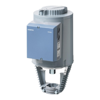
The Flowrite 599 Series SKB/C/D62UA Electronic Valve Actuator requires a 24 Vac
supply and receives a 0 to 10 Vdc or a 4 to 20 mA control signal to proportionally control
a valve. This actuator is designed to work with valves with a 3/4-inch (20 mm) or 1-1/2-
inch (40 mm) stroke.
•
Direct-coupled installation requires no special tools or adjustments
•
Visual and electronic stroke indication
•
Die-cast aluminum housing
•
Manual override
•
Spring return to fail-safe position
•
Automatic stroke calibration
•
Direct or reverse acting
•
Adjustable start and span
•
Stroke limit control
•
Choice of linear or equal-percentage flow characteristic
•
Maintenance-free
These electronic actuators are designed to be used with Flowrite 599 Series valves with
either 3/4-inch (20 mm) stroke (SKB/D) or a 1-1/2 inch (40 mm) stroke (SKC) in liquid
and steam service applications; or other manufacturer's valves with appropriate
Universal Valve Linkage Kits.
Technical Instructions
Document No. 155-717
September 25, 2018
SKB/C
SKD
Siemens Industry, Inc.
Advertisement
Table of Contents

Related Manuals for Siemens Flowrite 599 Series


Summary of Contents for Siemens Flowrite 599 Series
- Page 1 Maintenance-free Application These electronic actuators are designed to be used with Flowrite 599 Series valves with either 3/4-inch (20 mm) stroke (SKB/D) or a 1-1/2 inch (40 mm) stroke (SKC) in liquid and steam service applications; or other manufacturer's valves with appropriate Universal Valve Linkage Kits.
- Page 2 Technical Instructions Flowrite 599 Series SKB/C/D 62UA Electronic Valve Actuator Advanced Features Document Number 155-717 September 25, 2018 Product Numbers Table 1. Product Numbers. Actuator Order Number Stroke SKB62UA 3/4-inch (20 mm) SKD62UA 1-1/2 inch (40 mm) SKC62UA Warning/Caution Notations...
- Page 3 Flowrite 599 Series SKB/C/D 62UA Electronic Valve Actuator Advanced Features Technical Instructions Document Number 155-717 September 25, 2018 Terminal Y Signal Inputs Voltage 0 to 10 Vdc Input impendence 100K ohm Current 4 to 20 mA Input impedance 240 ohm Signal resolution <1%...
- Page 4 Technical Instructions Flowrite 599 Series SKB/C/D 62UA Electronic Valve Actuator Advanced Features Document Number 155-717 September 25, 2018 Materials Miscellaneous Actuator housing and bracket Die-cast aluminum Housing box and manual adjustor Plastic Conduit opening 1/2-inch NPSM Dimensions See Figure 23, Figure 24, Figure 25 and Figure 26.
-
Page 5: Service Kits
Flowrite 599 Series SKB/C/D 62UA Electronic Valve Actuator Advanced Features Technical Instructions Document Number 155-717 September 25, 2018 Accessories, 599-10071 The SKD actuator is UL listed to Continued meet NEMA TYPE 3R requirements (a degree of protection against rain, sleet, and damage... -
Page 6: Standard Operation
Technical Instructions Flowrite 599 Series SKB/C/D 62UA Electronic Valve Actuator Advanced Features Document Number 155-717 September 25, 2018 Valve Details, Continued 1. Pressure cylinder 2. Piston 3. Oscillating pump 4. Return spring 5. Bypass valve 6. Valve stem retainer 7. Manual override knob Position indicator Figure 7. -
Page 7: Mounting And Installation
Flowrite 599 Series SKB/C/D 62UA Electronic Valve Actuator Advanced Features Technical Instructions Document Number 155-717 September 25, 2018 Mounting and The vertical position is the recommended position for mounting and the only position for NEMA Type 3R rating with the Weather Shield. Acceptable mounting positions are shown Installation in Figure 10. - Page 8 Technical Instructions Flowrite 599 Series SKB/C/D 62UA Electronic Valve Actuator Advanced Features Document Number 155-717 September 25, 2018 Stroke Calibration To determine the stroke positions 0% and 100% in the valve, calibration is required when the valve/actuator are commissioned for the first time. The actuator must be mechanically connected to a valve and must have a supply voltage of 24 Vac.
- Page 9 Flowrite 599 Series SKB/C/D 62UA Electronic Valve Actuator Advanced Features Technical Instructions Document Number 155-717 September 25, 2018 Start-up, Continued Advanced Features Figure 13. DIP Switches. DIP Switches Select Sequence Control Selection of Selection of (From Left to Right) Direction of...
- Page 10 Technical Instructions Flowrite 599 Series SKB/C/D 62UA Electronic Valve Actuator Advanced Features Document Number 155-717 September 25, 2018 • With normally-closed valves, "direct-acting" means that with a 0 Vdc signal input, the valve Start-Up, is closed. continued • With Normally-open valves, "direct-acting" means that with a 0 Vdc signal input, the valve is open.
- Page 11 Flowrite 599 Series SKB/C/D 62UA Electronic Valve Actuator Advanced Features Technical Instructions Document Number 155-717 September 25, 2018 Start-up, continued When actuator pressure cylinder: Moves outward (0 to 1): Valve opens. Normally Closed Valve Moves inward (1 to 0): Valve closes.
- Page 12 Technical Instructions Flowrite 599 Series SKB/C/D 62UA Electronic Valve Actuator Advanced Features Document Number 155-717 September 25, 2018 Start-up, Continued When returning to automatic control, you must turn the crank arm of the manual setting knob counterclockwise until the red numbers disappear. It is essential that the Automatic Operation window is clear and the crank arm is snapped into position.
-
Page 13: Wiring Diagrams
Flowrite 599 Series SKB/C/D 62UA Electronic Valve Actuator Advanced Features Technical Instructions Document Number 155-717 September 25, 2018 Wiring Do not use auto-transformers. Use earth ground isolating step-down Class II power supplies. Determine supply transformer rating by summing total VA of all actuators used. - Page 14 Technical Instructions Flowrite 599 Series SKB/C/D 62UA Electronic Valve Actuator Advanced Features Document Number 155-717 September 25, 2018 Wiring Diagrams, Continued System neutral (SN) red System potential (SP) black 24 Vac/30W Figure 21. Figure 22. Auxiliary Switch Stem Heating Element ASC1.6.
- Page 15 Flowrite 599 Series SKB/C/D 62UA Electronic Valve Actuator Advanced Features Technical Instructions Document Number 155-717 September 25, 2018 Dimensions, Continued Figure 24. Dimensions of 599-10071 SKD Weather Shield in Inches (Millimeters). Figure 25. Dimensions of SKB/C Weather Shield, 599-10071 in Inches (Millimeters).
- Page 16 Information in this publication is based on current specifications. The company reserves the right to make changes in specifications and models as design improvements are introduced. Flowrite is a trademark of Siemens Industry, Inc. Other product or company names mentioned herein may be the trademarks of their respective owners.
Need help?
Do you have a question about the Flowrite 599 Series and is the answer not in the manual?
Questions and answers