Advertisement
ACVATIX™
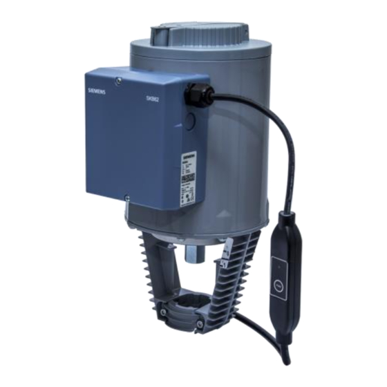
Electro-hydraulic actuators for valves
SKB..
CM1N4564en
2023-10-17
with a 20 mm stroke
●
SKB32.. Operating voltage AC 230 V, 3-position control signal
●
SKB82.. Operating voltage AC 24 V, 3-position control signal
●
SKB6.. Operating voltage AC 24 V
–
Control signal DC 0...10 V, 4...20 mA or 0...1000 Ω
–
SKB62/MO RS-485 for Modbus RTU communication
–
Selection of flow characteristic, position feedback, stroke calibration, LED
status indication, override control
–
SKB62UA with selection of direction of operation, stroke limit control,
sequence control with adjustable start point and operation range, operation of
frost protection monitors QAF21.. and QAF61..
●
Positioning force 2800 N
●
Versions with or without spring-return function
●
For direct mounting on valves; no adjustments required
●
Manual adjuster and position indicator
●
Optional functions with auxiliary switches, potentiometer, stem heater and
mechanical stroke inverter
●
SKB..U are UL-approved
Smart Infrastructure
Advertisement
Table of Contents

Related Manuals for Siemens ACVATIX SKB Series


Summary of Contents for Siemens ACVATIX SKB Series
- Page 1 ACVATIX™ Electro-hydraulic actuators for valves SKB.. with a 20 mm stroke ● SKB32.. Operating voltage AC 230 V, 3-position control signal ● SKB82.. Operating voltage AC 24 V, 3-position control signal ● SKB6.. Operating voltage AC 24 V – Control signal DC 0...10 V, 4...20 mA or 0...1000 Ω –...
- Page 2 For the operation of Siemens 2-port and 3-port valves of the types VVF.., VVG.., VXF.. and VXG.. with a 20 mm stroke as control and safety shut-off valves in heating, ventilation and air conditioning plants. Technical design Principle of electro-hydraulic actuators...
- Page 3 SKB62UA actuators. Notes on special programming of Frost the electronics are described under Electronics [➙ 5]. protection Connection diagrams for operation with frost protection thermostat or frost thermostat protection monitor can be found under Connection diagrams [➙ 26]. Siemens CM1N4564en Smart Infrastructure 2023-10-17...
- Page 4 * Factory setting: all switches OFF volumetric flow ** Only considered when DIL switch 3 ON (control signal = DC 4…20 mA) SKB60 , SKB62.. Connection terminals DIL switches LED status indication Stroke calibration Up to and including version ..K Siemens CM1N4564en Smart Infrastructure 2023-10-17...
- Page 5 DC 4...20 mA lin = linear Signal addition QAF21../QAF61.. OFF * Direct acting Stroke limit control DC 0...10 V log = equal percentage Relationship between positioning signal Y and * Factory setting: all switches OFF volumetric flow Siemens CM1N4564en Smart Infrastructure 2023-10-17...
- Page 6 In order to determine the stroke positions 0% and 100% in the valve, calibration is required on initial commissioning. Mechanical coupling of the actuator SKB6.. with a Siemens valve. Actuator must bin in „Automatic operation mode“ enabling stroke calibration to capture the effective 0% and 100% values.
- Page 7 Check mains network, check wiring Dark Electronics faulty Replace electronics As a general rule, the LED can only assume the states shown above – continuously lit red or green, flashing red or green, or off/dark. Siemens CM1N4564en Smart Infrastructure 2023-10-17...
- Page 8 ● With normally-closed valves, “direct acting” means that with a signal input of 0 V, the valve closes (applies to all Siemens valves listed under Equipment combinations [➙ 12]). ● With normally-open valves, “direct acting” means that with a signal input of 0 V, the valve is open.
- Page 9 The operating range of the frost protection monitor QAF21.. or QAF61.. can be defined with rotary switches LO and UP. Position of LO Sequence control Position of UP QAF21.. / QAF61.. start point operating range → QAF21.. → QAF61.. Siemens CM1N4564en Smart Infrastructure 2023-10-17...
-
Page 10: Type Summary
Accessories / spare parts Accessories Type Auxiliary Double Potentiometer Stem heater Mechanical 1000 Ω switch auxiliary AC 24 V stroke inverter switch ASC1.6 ASC9.3 ASZ7.3 ASZ6.6 ASK51 (S55845-Z108) Max. 2 SKB32.. Max.1 Max.1 SKB82 Max.1 Max.1 SKB6.. Max.1 Siemens CM1N4564en Smart Infrastructure 2023-10-17... - Page 11 The signal peaks that occur in the potentiometer ASZ7.3 may result in error messages on Siemens SIMATIC. This is not the case when combined with Siemens HVAC controllers. The reason is that SIMATIC has a higher resolution and faster response time.
-
Page 12: Ordering (Example)
15...40 0.16...40 N4405 VVF61.. 15...50 0.19...31 N4382 VVF63.. 15...50 0.2...36 A6V11459527 VVG41.. Threaded 15...50 0.63...40 N4363 Admissible differential pressures Δp and closing pressures Δp : cf. relevant valve data sheets Valves are no longer available Siemens CM1N4564en Smart Infrastructure 2023-10-17... -
Page 13: Product Documentation
For SKB32.. and SKB82.. the Y1 signal must be routed via an additional, freely adjustable end switch (ASC9.3) to limit the stroke. We recommend that you contact your local Siemens office for the necessary information. Product documentation SKB.. - Page 14 Dismount valve-actuator combination (control device) as complete unit. ● Disassembly only by qualified personnel. ● Send the control device along with an error report to the local Siemens office for analysis and disposal. ● Mount new control device (valve and actuator) properly.
- Page 15 Observe admissible temperatures, see Use [➙ 2] and Technical data [➙ 19]. If an auxiliary switch is used, its switching point should be indicated on the plant schematic. Every actuator must be driven by a dedicated controller, see Connection diagrams [➙ 26]. Siemens CM1N4564en Smart Infrastructure...
- Page 16 → stroke = 0 % → stroke = 100 % The manual adjuster must be rotated counter-clockwise to the end stop. This causes the Siemens valves, types VVF.. und VXF.. to close (stroke = 0 %). Operation Automatic operation For automatic operation, the crank [2] on the manual adjustment knob [1] must be engaged.
- Page 17 Release pressure in the pipes and allow them to cool off completely. WARNING Risk of injury ● Disconnect electrical connections from the terminals as neede. ● The actuator must be properly installed prior to recommissioning the valve. Siemens CM1N4564en Smart Infrastructure 2023-10-17...
- Page 18 Dismount valve-actuator combination (control device) as complete unit. ● Disassembly only by qualified personnel. ● Send the control device along with an error report to the local Siemens office for analysis and disposal. ● Mount new control device (valve and actuator) properly.
-
Page 19: Technical Data
Control signal SKB32.. 3-position SKB82.. DC 0…10 V SKB6.. DC 4…20 mA 0…1000 Ω Positioning signal Y SK6.. DC 0…10 V 100 kΩ Input impedance DC 4…20 mA 240 Ω Signal resolution < 1 % Hysteresis Siemens CM1N4564en Smart Infrastructure 2023-10-17... - Page 20 1-8-E-1 / 1-8-O-1 / 1-8-N-1 / 1-8-N-2 Factory setting 1-8-E-1 Baud rates (kBaud) Auto / 9.6 / 19.2 / 38.4 / 57.6 / 76.8 / 115.2 Factory setting Auto 120 Ω electronically switchable Bus termination Factory setting Siemens CM1N4564en Smart Infrastructure 2023-10-17...
- Page 21 AC 230 V AC 24 V UL 873 http://ul.com/database Environmental compatibility The product environmental declarations CE1E4564enX1 (SKB3.., SKB8..) , CE1E4564enX2 (SKB6..) A6V101083254 (external Modbus converter) contain data on RoHS compliance, materials composition, packaging, environmental benefit and disposal. Siemens CM1N4564en Smart Infrastructure 2023-10-17...
- Page 22 (Max. temperature 85 °C / 185 °F) At room temperature (23 °C); low ambient temperatures or high Δp may prolong these times From version ..L onward AWG = American wire gauge The documents can be downloaded at http://www.siemens.com/bt/download Siemens CM1N4564en Smart Infrastructure...
-
Page 23: Connection Diagrams
Neutral conductor SKB82.. SKB82.51 SKB82.50 AC 24 V 3-position End switch Solenoid valve for spring-return c1, c2 ASC9.3 double auxiliary switch a, b, c ASZ7.3 potentionmeter Positioning signal „open“ Positioning signal „close“ Spring-return function System potential Siemens CM1N4564en Smart Infrastructure 2023-10-17... - Page 24 Bus + (Modbus RTU) Positioning signal Bus - (Modbus RTU) Measuring neutral Operating voltage AC 24 V: System neutral (SN) Operating voltage AC 24 V: System potential (SP) Switching without power as a spring-return function Siemens CM1N4564en Smart Infrastructure 2023-10-17...
-
Page 25: Connection Terminals
Override control (Functions [➙ 8]) SKB62/MO AC 24 V Modbus RTU Connention cable System neutral (SN) Black System potential (SP) Reference line (Modbus RTU) Violet Bus + (Modbus RTU) Gray Bus - (Modbus RTU) Pink Auxiliary switch ASC1.6 Siemens CM1N4564en Smart Infrastructure 2023-10-17... - Page 26 Connection diagrams SKB32.. SKB32.51 SKB32.50 AC 230 V 3-position Positioning signal „open“ Safety limiter (e.g. temperature limiter) Positioning signal „close“ N1, N2 Controller Phase Y1, Y2 Actuators Neutral Spring-return function Siemens CM1N4564en Smart Infrastructure 2023-10-17...
- Page 27 SKB82.50, SKB82.50U AC 24 V 3-position Safety limiter (e.g. (Y1), Controller contacts temperature limiter) (Y2) Positioning signal „open“ System potential AC 24 V Positioning signal „close“ N1, N2 Controller System neutral Y1, Y2 Actuators Spring-return function Siemens CM1N4564en Smart Infrastructure 2023-10-17...
- Page 28 G0 (SN) System neutral Terminals: 1-2 Frost hazard/sensor is interrupted (thermostat closes with frost) 1-3 Normal operation Only SKB62UA: only with sequence control and the appropriate selector switch settings, see Electronics [➙ 5], Functions [➙ 6] Siemens CM1N4564en Smart Infrastructure 2023-10-17...
- Page 29 When using the safety limiter F1, ensure that no mistakes may occur on cable insulation that may cancel out the temperature limiter function (applies to both 230 V as well as 24 V types). ● For SN earthing (e.g. PELV) comply under all circumstances with the note above. Siemens CM1N4564en Smart Infrastructure 2023-10-17...
- Page 30 SKB..U: with knockouts for standard ½" conduit connectors (∅ 21.5 mm) > 100 mm, minimum clearance form ceiling or wall for mounting > 200 mm, connection, operation, maintenance, etc. Stroke inverter ASK51 All dimensions in mm Maximum stroke = 20 mm Siemens CM1N4564en Smart Infrastructure 2023-10-17...
-
Page 31: External Modbus Converter
External Modbus converter All dimensions in mm 250 mm Siemens CM1N4564en Smart Infrastructure 2023-10-17... - Page 32 SKB82.50 SKB62UA SKB82.50U SKB62/MO SKB82.51 SKB82.51U Issued by © Siemens Switzerland Ltd, 1998 - 2023 Siemens Switzerland Ltd Technical specifications and availability subject to change without notice. Smart Infrastructure Global Headquarters Theilerstrasse 1a CH-6300 Zug Tel. +41 58 724 2424 www.siemens.com/buildingtechnologies...
Need help?
Do you have a question about the ACVATIX SKB Series and is the answer not in the manual?
Questions and answers