Table of Contents
Advertisement
Advertisement
Table of Contents
Troubleshooting

Related Manuals for Heska Element DC


Summary of Contents for Heska Element DC
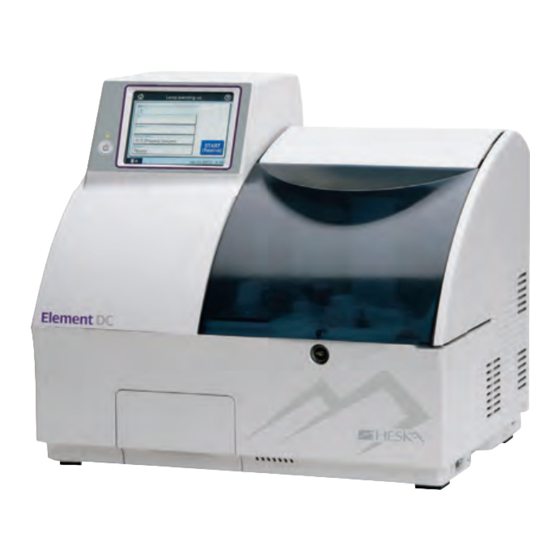
- Page 1 Element DC Veterinary Chemistry Analyzer product manual...
- Page 2 Introduction Thank you for purchasing the Element DC® Veterinary Chemistry Analyzer The Element DC is a diagnostic medical device for veterinary hospital use to analyze blood by colorimetric end-point, rate and ISE tests, using the DRI-CHEM SLIDES. Before using this equipment, please read this manual carefully to follow the precautions so that you can operate it correctly.
-
Page 3: Table Of Contents
Element DC Table of Contents Veterinary Chemistry Analyzer SECTION 1: SAFETY USAGE AND HANDLING PRECAUTIONS Definition of Specific Safety Precautions ..................................1 Precautions Before Operating This Equipment ..............................1 Biohazards and Disposal ........................................2 Explosive Hazards............................................2 Electrical Hazards ............................................2 Electromagnetic Compatibility (EMC)..................................3 Moving Parts ..............................................3 Installation Site Requirements ......................................4... - Page 4 SECTION 3: PRINCIPLES OF OPERATION Slide Loading ............................................25 Sample Loading ............................................25 Sampling and Spotting ........................................25 Incubation ..............................................25 Photometer and Potentiometer Readout................................25 Disposal of Consumables ........................................26 Preparations ...............................................26 3.7.1 List for Daily Maintenance Before Use ..............................26 3.7.2 Preparations before Turning the Power On (Daily Maintenance before Use #1) .............26 3.7.3 Turning the Power On (Daily Maintenance before Use #2) ....................27 3.7.4...
- Page 5 Inspecting and Replacing the Sampler O-ring ..............................58 4.7.1 Inspecting the Sampler O-ring ................................58 4.7.2 Replacing the Sampler O-ring .................................66 SECTION 5: TROUBLESHOOTING Error Indications ............................................61 5.1.1 Error Codes Table ......................................61 5.1.2 Printout Indications Table ...................................63 Troubleshooting .............................................65 5.2.1 Startup Errors ........................................65 5.2.2 Display or Printer Trouble ...................................65 5.2.3...
- Page 6 Basic/External I/F Settings <Admini.> ..................................86 6.8.1 Language Setting ......................................86 6.8.2 Date Format Setting.......................................87 6.8.3 Host I/F Settings .......................................88 6.8.4 Barcode Reader .........................................92 Display Settings <Admini.> ......................................94 6.9.1 Unit Conversion ........................................94 6.9.2 Display Method for Outside of Measurement Range .......................95 6.9.3 Reference Interval Settings ..................................97 6.9.4 Result Display Setting ....................................
-
Page 7: Definition Of Specific Safety Precautions
Veterinary Chemistry Analyzer Safe Usage and Handling Precautions This section contains safety precautions which must be followed for the safe operation of the Element DC® Veterinary Chemistry Analyzer. Before using this equipment, please read this chapter carefully and follow the precautions given, so that you can operate it correctly. -
Page 8: Biohazards And Disposal
WARNING When discarding the Element DC body that may be contaminated with blood samples, be sure to process it correctly in compliance with any applicable regulations in your country because it must never be disposed of as a general waste. -
Page 9: Electromagnetic Compatibility (Emc)
Consult the manufacturer or field service technician for help. CAUTION Do not use other devices (such as mobile phone) which generate and can radiate radio frequency energy near the Element DC. Otherwise, physical damage or malfunction on the Element DC may occur. Moving Parts WARNING Do not place your hands near the moving part (sampler, slide transfer bar, spotting part) whenever operating the equipment, including maintenance. -
Page 10: Installation Site Requirements
Type of protection against electrical shock: CLASS 1 EQUIPMENT Plug the Element DC into an independent AC outlet separate from other devices. Empty space is necessary at least 4 in (10 cm) on the back and the both sides of the equipment (Empty space on the back is necessary to unplug the power cable connector from the appliance inlet of the equipment). -
Page 11: Dri-Chem Slides
1.10 DRI-CHEM SLIDES (Henceforth, DRI-CHEM SLIDE is shortened into “slide” in this manual.) WARNING Do not touch used slides with bare hands as this may cause contamination. If any part of the body comes in contact with used slides, immediately rinse the contaminated body part thoroughly under running water and then use ethyl alcohol as a disinfectant. - Page 12 List of DRI-CHEM SLIDES for the Element DC. Alkaline Phosphatase v-AMY Amylase Creatine Phosphokinase Gamma Glutamyltransferase Enzymes GOT/AST Aspartate Aminotransferase GPT/ALT Alanine Aminotransferase Lactate Dehydrogenase v-LIP Pancreatic Lipase Albumin Blood Urea Nitrogen Calcium Biochemical Tests Creatinine Glucose Inorganic Phosphorus General...
-
Page 13: Qc Card System
For ISE tests, the reference fluid is necessary. Refer to the Instructions for Use for the slides. IMPORTANT Do not use products other than specified products designed for the Element DC, as using non-specified products could cause inaccurate test results and damage the analyzer. -
Page 14: Dri-Chem Auto Tips, Sample Tubes And Dri-Chem Mixing Cups
The sampler of the Element DC performs pipetting automatically. However, it is necessary to prepare the DRI-CHEM AUTO TIPS, Sample Tubes (Heparin Tube or Plain Tube) and DRI-CHEM MIXING CUPS designed for use with the Element DC. The Sample Tubes include the following: Heparin Tube 1.5... -
Page 15: Warning Labels
1.18 Warning Labels Warning labels and safety labels on the Element DC are: High temperature caution label Lamp caution label Biohazard label Key caution label Chemicals caution label Finger caution label Name-plate Power switch Power button Name-plate Power button Finger caution label... -
Page 16: Section 2: Component Names And Functions
Element DC Section 2: Component Names and Functions Veterinary Chemistry Analyzer Component Names Printer LCD Touch Panel Sampler Cover LCD Under Cover Card Reader Front Under Cover Disposal Box Sampler Incubator Cable Sample Rack Incubator Cover Light Source Lamp Slide Reader (inside) - Page 17 Circuit Protector LAN Terminal Appliance Inlet RS232C Connector Air Filter (Louver) Power Switch Sampler Cover Lock USB Connector (Only for the sample barcode reader) NOTE: Do not connect any USB device other than the sample barcode reader...
-
Page 18: Names And Functions Of Touch Panel Display
TOP dialogue is displayed. ① Help button The Help button is used for displaying the help dialogue. Element DC (Refer to Section 2.2.5) Measurement button ② The Measurement button is used for displaying the test ③... -
Page 19: Test Preparation Dialogue
2.2.2 Test Preparation Dialogue The test preparation dialogue is for preparing and setting a test. The dialogue is displayed after the power is turned on and the analyzer starts up. IMPORTANT In dialogues (including test preparation dialogue) displayed when performing tests, there are 2 kinds of dialogue: one is the basic dialogue, which does not display the sample state display area;... - Page 20 c. [Animal]: Reference interval settings When touching ANIMAL FIELD, the animal dialogue is displayed. Select the animal. If there is more than one animal page, touch the button to switch page. NOTE: To cancel the reference interval settings, touch X. d.
- Page 21 Operation Steps and Screen Displays for Basic Dialogue ① Basic Before Testing Make sure [Ready to test] is displayed. Input the sample information. If the device is connected to PMS, you can obtain test requests by touching WORK LIST in the test preparation dialogue before performing tests.
- Page 22 Operation Steps and Screen Displays for Advanced Dialogue Before Testing ① Advanced Make sure [Ready to Test] is displayed. Touch NEW TEST, and input the sample information. If the device is connected to PMS, you can obtain test requests by touching WORK LIST in the test preparation dialogue before performing tests.
-
Page 23: Mode Function Dialogue
The correlation coefficients reset to a=1 and b=0, the units reset to Unit (A) and the dilution factors reset to no dilution. (Refer to Section 6.2) NOTE: this is not used for Heska Chemistry Control. MODE FUNCTION buttons <Normal> The MODE FUNCTION buttons are used for displaying a respective MODE FUNCTION dialogue to be used by normal operators. - Page 24 Result data SCROLL button ① ② ③ The Result data SCROLL button is used for scrolling up or down a list of the test results. Result Data Display Area Test results are displayed in the result data display area. You can display or hide indicator.
-
Page 25: Help Dialogue
2.2.5 Help Dialogue The procedure of [Set (Blood)] or [Maintenance] (periodic maintenance) is displayed. [Others] provides descriptions of the test result signs. Operation method ITEM button ① The ITEM button is used for displaying help items. ② X button The X button is used to close the help dialogue. ITEM DETAIL buttons The ITEM DETAIL buttons are used for displaying details of a respective help item. -
Page 26: Names And Functions Of Screen Keyboard
Names and Functions of Screen Keyboard There are 2 kinds of screen keyboards: one is the ten-key keyboard; another is the alphanumeric keyboard. When entering numbers or letters during operation or setting, the screen keyboard pops up automatically. 2.3.1 Ten-Key Input Dialogue Numeric characters are input with ten-key. -
Page 27: Alphanumeric Input Dialogue
2.3.2 Alphanumeric Input Dialogue Alphanumeric characters are input. The input dialogue can be switched with the ABC button, abc button, 123 button or # button. <If the ABC button is selected> Capital letters and numbers can be input. NUMERIC buttons The NUMERIC buttons are used for inputting numeric characters. - Page 28 <If the abc button is selected> Lower case letters and numbers can be input. NUMERIC buttons The numeric buttons are used for inputting numeric characters. ALPHABETICAL (Lower case letters) buttons The ALPHABETICAL buttons are used for inputting alphabet in lower case letters. BKSP (Backspace) button The BKSP (Backspace) button is used for deleting the character on the left side of the cursor.
- Page 29 <If the 123 button is selected> Numeric characters can be input with ten-key. Refer to Section 2.3.1 for names and functions of the ten-key buttons. <If the # button is selected> Symbols and numeric characters can be input. NUMERIC buttons The NUMERIC buttons are used for inputting numeric characters.
-
Page 30: Slide Loading
Veterinary Chemistry Analyzer Operation This section provides an overview of the operations and the process that the Element DC needs to produce test results. Slide Loading The analyzer can compensate for the differences between the slide production lots by reading the QC card in the box of slides. -
Page 31: Disposal Of Consumables
Disposal of Consumables Used slides and tips are discarded into a disposal box. The used sample tubes, diluent, reference fluid, and mixing cups must be replaced by hand. Preparations To turn the power on the first time, depress the [ I ] side of the power switch which is located the right side of the analyzer. -
Page 32: Turning The Power On (Daily Maintenance Before Use #2)
Cutter-edge WARNING Do not touch the edge of the paper cutter with bare hands. 3.7.3 Turning the Power On (Daily Maintenance before Use #2) Close the sampler cover. Lock the sampler cover with the key. WARNING During sample processing, ensure the LCD under cover and sampler cover are closed to prevent injuries and biohazard. - Page 33 NOTE: Turning the power on for the first time or leaving the power continuously off for a long time may cause the date error (error code: E0500) prompting the resetting of the date. In this case, set the date and the time using the [Date & Time Settings] of MODE FUNCTION. (Refer to Section 6.3) NOTE: At the beginning of a month, the [Perform Periodic Maintenance] dialogue may be displayed.
-
Page 34: List For Daily Maintenance After Use
Be sure to replace the mixing cup for tests that require dilution. NOTE: If analyzer will not be used for a long time, depress the Element DC [ ] side of the power switch. Remove the disposal box and dispose of the tips and slides. -
Page 35: Sample Racks
Clean around the sample rack and the spotting part. Clean Use swabs moistened with ethyl alcohol as a disinfection for cleaning. WARNING When disinfecting (cleaning) the analyzer, always follow biohazard procedures (e.g., wearing gloves, lab coat, and safety goggles). If any part of the body comes in contact with contaminated parts, immediately rinse the contaminated body part thoroughly under running water and then use ethyl alcohol as a disinfectant. -
Page 36: Producing Samples Using Sample Tubes
Sample rack assembly for a 0.5 mL sample tube. Insert the tube holder “4” (for 0.5 mL tubes) in the hole. Place label “0.5 ml”. Insert pins “7” in the right (back view) and the center holes. The tube contents of a blood collection tube determine which slide is applicable. The following is general information about tube contents and the applicable tests. -
Page 37: Qc Card System
Make sure [Ready to test] or [Warming up] is displayed. b. Insert a QC card into the card reader on the right-hand side of the Element DC, and pull it towards you slightly. c. The test name and lot number are indicated on the display and the printer. -
Page 38: Measurement
Measurements 3.8.1 Basic Measurements (excluding ISE tests and tests that require dilution) Make sure [Ready to Test] is displayed. Open the sampler cover. Set a sample rack. Set a specified sample rack for the test tube to be used at the 1 SET POSITION (indicated by the label) on the analyzer. - Page 39 IMPORTANT The sample type and the sample type setting of the Element DC must be same. Otherwise, the wrong test result will be obtained. IMPORTANT For further information of the reference interval settings, refer to the Reference interval settings of MODE FUNCTION.
- Page 40 (Supplement) About Automatic Test Start If the analyzer is not used for a period of time, the light source Element DC lamp is turned off to save lamp life. This time period is set in the lamp configuration MODE FUNCTION.
-
Page 41: Usage Of The Work List Button
NOTE: PMS is sold separately. Touch the WORK LIST button. The Element DC receives a work list (a list of patients and their samples to be tested) from PMS. The work list index dialogue is displayed. - Page 42 Touch an item listed. The requested item is displayed in the work list test preparation dialogue. If there is more than one list, touch the button to or move to another page. NOTE: By touching CANCEL, the display returns to the test preparation dialogue.
-
Page 43: Ise Tests
3.8.3 ISE Tests Make sure [Ready to Test] is displayed. Open the sample cover. Set a sample rack. Set a specified sample rack for the test tube to be used at the 1 SET POSITION (indicated by the label) on the analyzer. NOTE: Be sure to set the sample rack down to the bottom. -
Page 44: Tests That Require Dilution
Section 2.2.2. Refer to Section 2.3 for input at the screen keyboard dialogue. IMPORTANT The sample type and the sample type setting of the Element DC must be same. Otherwise, the wrong test result will be obtained. IMPORTANT For further information of the reference interval settings, refer to the Reference interval settings of MODE FUNCTION. - Page 45 Make sure [Ready to Test] is displayed. Open the sampler cover. Set a sample rack. Set a specified sample rack for the test tube to be used at the 1 SET POSITION (indicated by the label) on the analyzer. NOTE: Be sure to set the sample rack down to the bottom. Obtain test information from PMS (If the device is connected to PMS).
- Page 46 Section 2.2.2. Refer to Section 2.3 for input at the screen keyboard dialogue. IMPORTANT The sample type and the sample type setting of the Element DC must be same. Otherwise, the wrong test result will be obtained. IMPORTANT For further information of the reference interval settings, refer to the Reference interval settings of MODE FUNCTION.
-
Page 47: Setting Slides
15. After the tests are completed, dispose of the used mixing cup and remove the remaining sample. WARNING When discarding used mixing cups, always follow biohazard procedures (e.g., wearing gloves, lab coat, and safety goggles), referring to the sample handling rules at your facility. If any part of the body comes in contact with samples, immediately rinse the contaminated body part thoroughly under running water and then use ethyl alcohol as a disinfectant. -
Page 48: Rerunning Tests
Inappropriate slide stacking orders Avoid performing tests with more than one dilution factor setting for one sample. NOTE: One dilution factor can be set for one sample. The example shows 2 ISE slides stacked on the slide cartridge. When performing an ISE test, tips are disposed of each time an ISE slide is measured. -
Page 49: Sample Barcode Reader
(Refer to Section 6.8.4) CAUTION The sample barcode reader specified for the Element DC can be used. Do not connect a barcode reader other than specified for the Element DC. Otherwise, physical damage or danger of fire may result. IMPORTANT Depending on the printing quality of barcode labels or malfunction of the sample barcode reader, wrong barcode data may be read. -
Page 50: Operating Procedures
NOTE: Please carefully read the instruction included with the sample barcode reader before using it. A maximum of 13 alphanumerical characters can be input for a sample ID. Always use the sample barcode reader below 3,000 cd/m (lux), avoiding direct sunlight. NOTE: Turn on the analyzer after connecting the sample barcode reader to the analyzer. -
Page 51: Editing Sample No. And Sample Id
Sample ID scanned by the barcode reader After completing the reading, a beep will be heard and the Sample ID will be displayed. IMPORTANT Make sure that the barcode data (sample ID) displayed in the test result dialogue is correct. Wrong reading will cause an incorrect report to doctors. -
Page 52: Section 4: Periodic Maintenance
Section 4: Periodic Maintenance Veterinary Chemistry Analyzer Periodic Maintenance In order to keep the Element DC performance at its best, perform the periodic maintenance by users and the specific maintenance by technical support (dealer). WARNING When performing maintenance (cleaning the analyzer), always follow biohazard procedures (e.g., wearing gloves, lab coat, and safety goggles). -
Page 53: User Daily/Periodic Maintenance
If the air filter is not cleaned, the temperature inside the analyzer will increase resulting in adverse effects on test results. 4.2.1 Cleaning procedures Turn off the power of the Element DC. Remove the louver, and then take out the air filter. Louver... -
Page 54: Cleaning The Incubator, Spotting Part And Ise Unit
Remove dust adhering to the filter with a vacuum cleaner or running water. If washing the filter with running water, make sure it is dried well before putting it back. Air filter Set the filter in the louver and close cover. IMPORTANT If the analyzer is used without setting the filter, adverse effects on test results may occur. - Page 55 Confirm the results displayed in the Reference plate level check dialogue. Check result: [1(0%) OK] a. If the result is [1 (0%) OK], cleaning is not needed. Touch to return to the TOP dialogue. b. If the result is [2(50%) OK] or [3(80%) NG], cleaning is needed.
- Page 56 b. Remove the incubator cover. Incubator cover c. Unscrew 5 screws on upper incubator and remove the incubator. Thumbscrew d. Wipe off 13 pressure plates on the underside of the incubator Pressure plate with soft gauze-like cloth or cotton swab moistened and tightly wrung out with sterilizing ethyl alcohol or isopropyl alcohol.
- Page 57 Turn over the reference plate and clean the white plate Reference Reference black plate white plate and the black plate with a dry cotton swab. IMPORTANT Do not touch the surface of the black plate and the white plate with bare hands. Otherwise, adverse effects on test results may occur.
- Page 58 Wipe off the spotting part with soft gauze-like cloth or cotton swab moistened with water. Spotting part Cleaning the slide transfer bar. Transfer (slide feed) bar Wipe off the slide transfer bar with soft gauze-like cloth or cotton swab moistened with water. NOTE: For the slide transfer bar left edge, move the slide transfer bar to the right.
-
Page 59: Cleaning The Slide Reader
Incubator cable Incubator cover IMPORTANT Tighten the thumbscrews securely. Otherwise, adverse effects on the test results may occur. IMPORTANT Be sure to set incubator cover. If the analyzer is used without setting the cover, adverse effects on test results may occur. NOTE: To avoid stressing the cable, ensure that the incubator Incubator cable cable is not twisted. -
Page 60: Replacing The Recording Paper
A red line appearing along the sides of the recording paper means that the printer is nearly out of paper. Replace the recording paper roll with a new one. NOTE: Use specified recording paper for the Element DC. 4.5.1 Replacement procedure Open the printer cover. -
Page 61: Replacing And Cleaning The Light Source Lamp
(10)Pass paper through Lock the lever. opening and close cover Make sure that the paper will advance straight and then lower the lever to lock the paper. 10. Close the printer cover. Pass the paper through the cutter opening on the printer cover and close the cover. - Page 62 Lens Wipe off the light source unit lens in the analyzer using a dry cotton swab. NOTE: If cleaning with alcohol, always wipe off the lens using a dry cotton swab to dry it well. Unscrew the thumbscrew of the lamp unit and replace the lamp with a new one.
-
Page 63: Inspecting And Replacing The Sampler O-Ring
Inspecting and Replacing the Sampler O-ring The sampler nozzle O-ring wears with use. Periodic inspection (once a month) and replacement (once a year) is necessary. IMPORTANT If the analyzer is used without inspecting and replacing the sampler O-ring, spotting volume may be inaccurate to cause adverse effects on test results. - Page 64 Touch OK. The sampler leak check is executed, and the leak check proceeding dialogue is displayed. After the leak check is complete, the leak check result dialogue is displayed. NOTE: By touching , the check results are printed out. NOTE: When touching RESULT DETAILS, the check result details dialogue is displayed.
-
Page 65: Replacing The Sampler O-Ring
After the leak check is complete, the leak check result dialogue is displayed. NOTE: By touching , the check results are printed out. NOTE: When touching RESULT DETAILS, the check result details dialogue is displayed. By touching OK, the check result details dialogue disappears. f. -
Page 66: Section 5: Troubleshooting
Element DC Section 5: Troubleshooting Veterinary Chemistry Analyzer Troubleshooting WARNING When performing troubleshooting, always follow biohazard procedures (e.g., wearing gloves, lab coat, and safety goggles). If any part of the body comes in contact with contaminated parts, immediately rinse the contaminated body part thoroughly under running water and then use ethyl alcohol as a disinfectant. - Page 67 Error Code Error Description Reference Section Reference Page E0129 Failed to detect reference fluid surface 5.2.4 E0140–E0146 Liquid volume error 5.2.4 E0200–E0210 Errors related to slide transfer 5.2.6 E0300–E0302 Reference white plate read error during initialization 5.2.8 E0500, E0501 Date error 5.2.8 E0509, E0510 Circuit board malfunction...
-
Page 68: Printout Indications Table
Error Code Error Description Reference Section Reference Page W090, W097, W099 Data communication error 5.2.12 W110 No tip has been set 5.2.4 W112 No tip for the next test 5.2.4 W115, W116 Tip eject error 5.2.4 W120 Tip sensor error 5.2.4 W140 An ISE slide is loaded in incorrect direction... - Page 69 Printout Message Description and status Solution Impossible to calculate the concentration of the sample because of some Check other errors previously interruption (e.g., slide jam) of testing. occurred, and perform the necessary troubleshooting. The test results will be printed out as “****”. Rerun the tests.
-
Page 70: Troubleshooting
Check that the power cable is properly connected and the circuit protector is not turned off. Then try turning on the analyzer again. If the analyzer does not start, please contact Heska's Technical Support Services for assistance. If the circuit protector is turned off (button protruding), contact Heska's Technical Support Services for assistance. 5.2.2 Display or Printer Trouble White lines appear or certain parts of characters are not printed out: •... -
Page 71: Sampler Errors
5.2.4 Sampler Errors Error Code Error Message Error Status Solution W110 No tip WARNING During the tip detection Put a tip in the setting position and rerun the No tip detected. Check tips "a" to "d". process, the analyzer could tests from the beginning. - Page 72 Sampler rotation motor ERR movement area. Remove foreign matter if exists. E1101 E1103 c. Turn the power switch on. d. If the error still occurs, please contact Heska's E1102 Sampler rotation motor operation ERR Technical Support Services for assistance. E1200 Syringe motor ERR...
-
Page 73: Photometer Errors
E510 Faulty A/D controller The circuit board has malfunction Turn the power switch off and on. If the (abnormal reference white plate error still occurs, please contact Heska's reading). Technical Support Services for assistance. E0900 Filter motor ERR Interference motor drive error has E0901 occurred. -
Page 74: Transfer Errors
Feed motor ERR 3. Spotting part cleaning (Refer to E0207 Rerun the tests. Section 4.3). E0210 Feed motor ERR If the error still occurs, please contact Heska's Technical Support Services for E0600 Incubator motor ERR assistance. E0601 E0602 Incubator motor ERR E0603 Incubator motor ERR Check Disposal box. -
Page 75: Circuit Board Malfunction
Set date & time. been reset. MODE FUNCTION. (Refer to Section 6.3) If the error still occurs, please contact Heska's Technical Support Services for assistance. Turning the power on for the first time or turning the power continuously off for a long time may cause the date error. -
Page 76: Qc Card/Di Card Read Error
Read the QC card again. (Refer to Section Read QC card again. information. 3.7.8.) If the error still occurs, please contact E4001 QC card ERR Heska's Technical Support Services for Read QC card after the assistance. measurement completed. E4003− QC card ERR E4009 Read QC card again. - Page 77 W141 Error Code Error Message Error Status Solution W141 Unacceptable ISE test E0530—E0532 occurred; analyzer has not Turn the power switch off and on, and ISE tests cannot run. been turned off (reset). then rerun the tests from the beginning. Turn the power SW OFF and ON.
-
Page 78: Errors Related To Data Communication Or Sample Barcode Reader
• Make sure that the status of the host computer is ready to communicate. • Make sure that the communication settings have been set correctly. (See Section 6.8.3) If the error still occurs, please contact Heska's Technical Support Services for assistance. W200 Barcode reader ERR... -
Page 79: Other Errors
• Make sure that the status of the host computer is ready to communicate. • Make sure that the communication settings have been set correctly. (See Section 6.8.3) If the error still occurs, please contact Heska's Technical Support Services for assistance. 5.2.13 Other Errors... -
Page 80: Section 6: Mode Settings And Functions
Element DC Section 6: Mode Settings and Functions Veterinary Chemistry Analyzer Mode Setting Procedure and Description There are 2 kinds of modes: one is the administrator mode, which can only be operated by administrators; another is the normal mode, which can be operated by normal operators. -
Page 81: How To Select Each Mode
Mode Function Menu Main Setting Menu Sub-Setting Menu Reference Section Operator Correlation coefficients 6.10.1 For administrator Coefficients/Test settings Lot compensation 6.10.2 coefficients Admin Dilution factor 6.10.3 Spotting count 6.10.4 Print sheets of test 6.10.5 results 6.1.2 How to Select Each Mode In the MODE FUNCTION menu dialogue, touch a MODE FUNCTION to be set. -
Page 82: Control Mode
Execution of the Control Mode This mode is only used for FUJI DRI-CHEM CONTROL QP-L or QP-H. This mode is not used for Heska Chemistry Control. When the control mode is selected, the analyzer calculates the concentration with the correlation coefficients for all tests reset to a=1 and b=0. -
Page 83: Buzzer Volume
Touch REGISTER. The set screen brightness is registered, and then the display returns to the MODE FUNCTION menu dialogue. NOTE: To cancel setting, touch CANCEL. Buzzer Volume <Normal> This mode is used to change the beep sound settings (error warning, end of a test). -
Page 84: Test End Sound
Touch REGISTER. The set error sound is registered, and then the display returns to the MODE FUNCTION menu dialogue. NOTE: To cancel setting, touch CANCEL. 6.5.2 Test End Sound Touch BUZZER VOLUME in the MODE FUNCTION menu dialogue. The buzzer volume dialogue is displayed. IMPORTANT There are 2 types of buzzer sound: one is error sound;... -
Page 85: Lamp Configuration
Touch REGISTER. The set test end sound is registered, and then the display returns to the MODE FUNCTION menu dialogue. NOTE: To cancel setting, touch CANCEL. Lamp Configuration <Normal> This mode is used to display and reset the cumulative illumination time of the lamp currently installed in the analyzer. The illumination time will be counted up to 9,999 hours without reset. - Page 86 To leave the lamp ON a. Touch NO in the [Lamp OFF:]. The [Lamp OFF Time:] field is grayed out and becomes invalid. b. Touch REGISTER. The [Lamp OFF:] is set to “No”, and then the display returns to the MODE FUNCTION menu dialogue. NOTE: To cancel setting, touch CANCEL.
-
Page 87: Display Information
Display Information <Normal> This mode is used to display the following: • Error log • Display temperature & humidity • Lot information • DI card information 6.7.1 Error log This mode is used to display error logs memorized in the analyzer. Touch DISPLAY INFORMATION in the MODE FUNCTION menu dialogue. -
Page 88: Display Temperature & Humidity
6.7.2 Display Temperature & Humidity This mode is used to display CM & ISE incubator temperature and environmental temperature & humidity (inner body). Touch DISPLAY INFORMATION in the MODE FUNCTION menu dialogue. The display INFORMATION menu dialogue is displayed. Touch DISPLAY TEMPERATURE & HUMIDITY in the menu dialogue. -
Page 89: Di Card Information
Touch LOT INFORMATION in the menu dialogue. The lot information dialogue is displayed. By touching or , you can see all lot information. NOTE: Test name, test type, lot No. and expire date are displayed. NOTE: Test names are displayed in ascending order of test code. Sample types are displayed in order of: [P/S] and [W]. - Page 90 Display information on the selected test. a. Touch desired test name. The DI card information item dialogue is displayed. By touching or , you can see all test information. NOTE: Test name, sample type and DI value are displayed. NOTE: Sample types are displayed in order of: [P/S] and [W]. NOTE: When touching , all lot information presently registered are printed out.
-
Page 91: Basic/External I/F Settings
Basic/External I/F Settings <Admini.> This mode is used to display the following. • Language setting • Date format setting • Host IF settings • Barcode reader 6.8.1 Language Setting This mode is used to set a language to be used in the equipment. Touch BASIC/EXTERNAL I/F SETTINGS in the ADMINISTRATOR MODE FUNCTION menu dialogue. -
Page 92: Date Format Setting
6.8.2 Date Format Setting This mode is used to set the order of the date (year, month and day). Touch BASIC/EXTERNAL I/F SETTINGS in the ADMINISTRATOR MODE FUNCTION menu dialogue. The BASIC/EXTERNAL I/F SETTING menu dialogue is displayed. NOTE: For information about how to display the ADMINISTRATOR MODE FUNCTION menu dialogue, refer to Section 6.1.2. Touch DATE FORMAT SETTING in the menu dialogue. -
Page 93: Host I/F Settings
6.8.3 Host I/F Settings This mode is used to connect the Element DC to a host computer (PC) and to set communication parameters. Also, this mode is used for turning the built-in printer ON/OFF. NOTE: Do not connect the Element DC to the host computer, which has not been approved by IEC/UL60950−1. - Page 94 To not connect to the host computer a. Touch NO. NOTE: Other buttons except for REGISTER and CANCEL are grayed out and become unselectable. b. Touch REGISTER. The host I/F setting is set to [No], and then the display returns to the BASIC/EXTERNAL I/F SETTING menu dialogue.
- Page 95 Select ON to use the printer. Select OFF to not use the printer. d. Touch LAN SETTINGS. The LAN settings dialogue is displayed. NOTE: The LAN settings’ defaults are as follows. Element DC settings IP address: 192.168.100.1 Port No.: 65535 PC settings IP address: 192.168.100.2...
- Page 96 Section 2.3. NOTE: To cancel EDIT and return to the LAN settings dialogue, touch X. f. Enter the IP address (Element DC), and then touch OK. The screen keyboard to enter the Port No. (Element DC) is displayed.
-
Page 97: Barcode Reader
This mode is used to perform the setting to connect the sample barcode reader to the USB connector. CAUTION The sample barcode reader specified for the Element DC can be used. Do not connect a barcode reader other than one specified for the Element DC. Otherwise, physical damage or danger of fire may result. - Page 98 Touch BARCODE READER in the menu dialogue. The BARCODE READER SETTING menu dialogue is displayed. To use the barcode reader: To not use the barcode reader: To use the barcode reader a. Touch YES. b. Touch REGISTER. The barcode reader setting is set to [Yes], and then the display returns to the BASIC/EXTERNAL I/F SETTING menu dialogue.
-
Page 99: Display Settings
b. Touch REGISTER. The barcode reader setting is set to [No], and then the display returns to the BASIC/EXTERNAL I/F SETTING menu dialogue. NOTE: To cancel setting, touch CANCEL. Display Settings <Admini.> The following settings are possible in this mode. •... -
Page 100: Display Method For Outside Of Measurement Range
Touch UNIT to be changed. (e.g.,) Change the unit for GLU from [mg/dl] to [mmol/l]. Touch REGISTER. The set unit conversion is registered, and then the display returns to the DISPLAY SETTINGS menu dialogue. NOTE: To cancel setting, touch CANCEL. 6.9.2 Display Method for Outside of Measurement Range This mode is used to switch the display method for results outside of the measurement range for all tests. - Page 101 To display a numeric value with “@” mark for the value outside of the measurement range a. Touch @. IMPORTANT Measured values with a “@” mark may NOT be accurate. Rerun the tests. b. Touch REGISTER. The set @ is registered, and then the display returns to the DISPLAY SETTINGS menu dialogue.
-
Page 102: Reference Interval Settings
6.9.3 Reference Interval Settings This mode is used to change the display order of items shown in the dialogue, and also is used to edit or add items. A reference interval must be set for each item name and sample type ([P/S or W]). Touch DISPLAY SETTINGS in the ADMINISTRATOR MODE FUNCTION menu dialogue. - Page 103 To change the display order of reference interval items in the dialogue: To edit a reference interval item : 2 To edit a reference interval item: 3 To change the display order of reference interval items in the dialogue. a. Touch the item to be changed. (e.g.,) Select [Cat (18)] The selection dialogue is displayed.
- Page 104 To edit a reference interval item a. Touch the item to be changed. (e.g.,) Select [Cat (18)] The selection dialogue is displayed. b. Touch EDIT. The edit dialogue is displayed. NOTE: By touching [P/S, W] the display switches from one tab to another.
- Page 105 To edit a reference interval item a. Touch the item to be changed. (e.g.,) Select [Cat (18)] The selection dialogue is displayed. b. Touch EDIT. The edit dialogue is displayed. NOTE: By touching [P/S, W] the display switches from one tab to another.
-
Page 106: Result Display Setting
f. Enter values in the [Lower limit:] field, and then touch OK. The screen keyboard to input the upper limit appears. g. Enter values in the [Upper limit:] field, and then touch OK. The edit dialogue for an individual test name is displayed. h. -
Page 107: Sample No./Id Settings
Touch YES or NO in the [Indicator:]. Touch YES or NO in the [Reference interval printout:]. Touch REGISTER. The result display settings are registered, and then the display returns to the DISPLAY SETTINGS menu dialogue. NOTE: To cancel setting, touch CANCEL. 6.9.5 Sample No./ID Settings This mode is used to set the display/not display of sample No. -
Page 108: Work List Selection Setting
Touch YES or NO in the [Keep sequence No.:]. Touch REGISTER. The sample No./ID settings are registered, and then the display returns to the DISPLAY SETTINGS menu dialogue. NOTE: To cancel setting, touch CANCEL. 6.9.6 Work List Selection Setting This mode is used to set the work list index display. Touch DISPLAY SETTINGS in the ADMINISTRATOR MODE FUNCTION menu dialogue. -
Page 109: Correlation Coefficients
6.10.1 Correlation Coefficients This mode is used to input, reset or print out correlation coefficients (a, b) for each test and for each sample type (P/S, and W). For further details, refer to the Description of the Correlation Function at the end of this section. IMPORTANT Incorrect inputs for (a, b) will cause incorrect test results. - Page 110 Touch the test name to be edited. (Example) GLU The edit dialogue is displayed. NOTE: The sample type presently recorded in the analyzer has been selected. NOTE: When touching RESET, the reset confirmation dialogue appears. Touch OK to reset the selected test name and the correlation coefficients for the selected sample type.
- Page 111 Description of the correlation function Y=aX+b This function is designed to determine the correlation between the measured data obtained using the Element DC and the data obtained using the conventional measuring method with your own instruments. On the X-axis, the measured data obtained using your instruments are plotted and on the Y-axis, the measured data obtained using the Element DC.
- Page 112 X = (Y-b)/a In this way, the Element DC’s measured data (Y) are adjusted to match those that would be obtained using your instruments with the conventional method. NOTE: In order to obtain a better correlation, it is essential to exercise caution regarding the amount of data and the sample.
-
Page 113: 6.10.2 Lot Compensation Coefficients
IMPORTANT Measured values with a “@” mark may NOT be accurate. Rerun the tests. 6.10.2 Lot Compensation Coefficients This mode is used to input the values (c, d, e) printed on the QC cards included with slides. This mode is needed if it is not possible to read in the data directly from a QC card that was lost or damaged. - Page 115 Input value in the [c: ], and then touch OK. The screen keyboard to input the lot compensation coefficient (d ) appears. Input value in the [d:], and then touch OK. The screen keyboard to input the lot compensation coefficient (e ) appears.
-
Page 116: Dilution Factor
11. Touch REGISTER. The input values are registered, and then the display returns to the lot No. list dialogue. NOTE: To cancel setting, touch CANCEL. 6.10.3 Dilution Factor This mode is used to set dilution factors for each test and for each sample type (P/S or W). -
Page 117: Spotting Count
Select the desired dilution factors for the [PS:], and then touch REGISTER. Dilution factor settings are registered, and the display returns to the dilution factor dialogue. NOTE: A dilution factor of 1 means no dilution. A dilution factor of 2 is a 1:1 dilution, etc. NOTE: To cancel setting, touch CANCEL. - Page 118 Touch PRINT SHEETS OF TEST RESULTS in the menu dialogue. The dialogue to set a number of test result print sheets is displayed. NOTE: To cancel setting, touch CANCEL. Select the desired number of sheets, and then touch REGISTER. The setting is registered, and then the display returns to the COEFFICIENTS/TEST SETTINGS menu dialogue.
-
Page 119: Data Communication
The Element DC Veterinary Chemistry Analyzer can transmit test results to the host computer or PC which has already been approved by IEC/UL60950−1. Do not connect the Element DC Veterinary Chemistry Analyzer to a host computer or PC which has not been approved by IEC/UL60950−1. -
Page 120: Section 8: Specifications/Consumables
Element DC Section 8: Specifications/Consumables Veterinary Chemistry Analyzer Specifications and Standard Accessories 8.1.1 Specifications Throughput: 128 tests per hour (simultaneous CM and ISE tests) Number of incubator cells: CM 12, ISE 1 Incubation temperature: 98.6°F (37°C) (CM) 86°F (30°C) (ISE) -
Page 121: Standard Accessories
NOTE: Do not change AC power cable to inappropriate one. NOTE: Specifications and capabilities are subject to change without notice. Consumables and Optional Accessories For purchasing consumables or optional accessories listed below, please contact the dealer from whom you purchased the Element DC. 8.2.1 Consumables Accessories Package... -
Page 122: Optional Accessories
*Slide weight CAUTION The sample barcode reader specified for the Element DC can be used. Do not connect a sample barcode reader other than one specified for the Element DC. Otherwise, damage or danger of fire may result. NOTE: Parts names marked with “ * ” are the same parts packed with the Element DC. -
Page 123: Section 9: Glossary
Element DC Section 9: Glossary Veterinary Chemistry Analyzer Glossary of the Display and Printout Messages Because the display spaces and printouts are limited, some abbreviations are used. Periods will not be used after abbreviations on the display and printout messages. - Page 124 For further assistance, please call Heska’s Technical Support Services at 800.464.3752, option 3. ©2018 Heska Corporation. All Rights Reserved. DRI-CHEM is a registered trademark of FUJIFILM Corporation. HESKA and Elemend DC are registered trademarks of Heska Corporation in the U.S.
Need help?
Do you have a question about the Element DC and is the answer not in the manual?
Questions and answers