
Related Manuals for Caen N957


Summary of Contents for Caen N957
- Page 1 Technical Information Manual Revision n. 6 28 May 2012 MOD. N957 8K MULTICHANNEL ANALYZER NPO: 00105/04:N957x.MUTx/06...
- Page 2 User. It is strongly recommended to read thoroughly the CAEN User's Manual before any kind of operation. CAEN reserves the right to change partially or entirely the contents of this Manual at any time and without giving any notice. Disposal of the Product The product must never be dumped in the Municipal Waste.
-
Page 3: Table Of Contents
Document type: Title: Revision date: Revision: User's Manual (MUT) Mod. N957 8k Multi-Channel Analyzer 28/05/2012 TABLE OF CONTENTS GENERAL DESCRIPTION......................... 6 ............................... 6 VERVIEW TECHNICAL SPECIFICATIONS ......................7 .............................. 7 ACKAGING ... - Page 4 Document type: Title: Revision date: Revision: User's Manual (MUT) Mod. N957 8k Multi-Channel Analyzer 28/05/2012 3.11 ) ....................23 ALIBRATION ET REGISTER 3.12 ) .................... 23 ALIBRATION LEAR REGISTER 3.13 ) ......................23 CRATCH REGISTER ...
- Page 5 Document type: Title: Revision date: Revision: User's Manual (MUT) Mod. N957 8k Multi-Channel Analyzer 28/05/2012 LIST OF FIGURES . 1.1: M . N957 B ....................... 6 LOCK IAGRAM . 3.1: M . N957 F ........................8 RONT PANEL ...
-
Page 6: General Description
1. General description Overview The Mod. N957 is a 8k Multi-Channel (MCA) with USB port, housed in a 1-unit wide standard NIM module. The multichannel analyzer performs the essential function of collecting the data and producing output, in the form of converted value of input peaks. -
Page 7: Technical Specifications
Revision date: Revision: User's Manual (MUT) Mod. N957 8k Multi-Channel Analyzer 28/05/2012 2. Technical specifications Packaging The Model N957 is housed in a single width NIM module. Power requirements Table 2.1: Power requirements +12 V 220 mA -12 V 220 mA... -
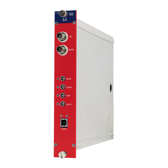
Page 8: Front And Back Panel
Revision date: Revision: User's Manual (MUT) Mod. N957 8k Multi-Channel Analyzer 28/05/2012 Front and back panel Mod. N957 GATE BUSY CONV OUTP TX/RX LINK ON LINK Fig. 2.1: Mod. N957 Front panel NPO: Filename: Number of pages: Page: 00105/04:N957x.MUTx/06 N957_REV6... -
Page 9: Input/Output Connections
Document type: Title: Revision date: Revision: User's Manual (MUT) Mod. N957 8k Multi-Channel Analyzer 28/05/2012 Input/Output connections Type: Input Function: Unipolar (positive) or bipolar in a range from 0 to +10 V, with a rise time greater than 0.1 µs, high impedance. BNC connector (to be connected to Amplifier Analog output);... -
Page 10: Internal Hardware Components
“Back up” firmware must be loaded at power on; (default position: STD). SW1 switch for DAUGHTER BOARD NIM/TTL logic level selection J6 jumper for firmware selection N957 FPGA USB SECTION Fig. 2.2: Mod. N957 PCB boardand component location NPO: Filename: Number of pages: Page: 00105/04:N957x.MUTx/06 N957_REV6... -
Page 11: Technical Specification Table
Revision: User's Manual (MUT) Mod. N957 8k Multi-Channel Analyzer 28/05/2012 Technical specification table Table 2.2: Mod. N957 Technical Features No. of ADC channels Unipolar (positive) or bipolar, 300 mV ÷ 10 V range, Input signals rise time> 0.1 µs 13 bit (8192 channels - 8064 valid if sliding scale enabled see 2.8) Resolution 0.8 µs... -
Page 12: Analog To Digital Conversion Timing
Title: Revision date: Revision: User's Manual (MUT) Mod. N957 8k Multi-Channel Analyzer 28/05/2012 2.8.1 Analog to digital conversion timing The signal conversion timing is shown in the following figures (Fig. 2.3, Fig. 2.4, Fig. 2.5 ); the diagram includes five different logic states: ... - Page 13 Document type: Title: Revision date: Revision: User's Manual (MUT) Mod. N957 8k Multi-Channel Analyzer 28/05/2012 Threshold Input Peak detection Auto-Gate (Internal) PEAK section Output BUSY Output Conversion digitisa idle track settling clear idle Logic tion State 2s 0.8s 2s Fig. 2.3: Signal conversion timing Auto Gate mode (No Pileup)
-
Page 14: Pile Up Rejection
Document type: Title: Revision date: Revision: User's Manual (MUT) Mod. N957 8k Multi-Channel Analyzer 28/05/2012 INPUT Peak detection (absolute peak over threshold) GATE PEAK section Output BUSY Output Conversion Logic digitisa settling idle track clear idle tion State 2s 0.8s 2s... -
Page 15: Data Readout
Title: Revision date: Revision: User's Manual (MUT) Mod. N957 8k Multi-Channel Analyzer 28/05/2012 Data readout Converted peaks are stored into a 64 KSamples buffer memory, available for data readout via built-in USB2.0 interface (also compatible with USB1.1). Data rate depends, besides the connected PC capabilities, on the board setting via N957_ReadData function, which allows to read a data block of programmable size;... -
Page 16: Scaler And Timers
Document type: Title: Revision date: Revision: User's Manual (MUT) Mod. N957 8k Multi-Channel Analyzer 28/05/2012 2.10 Scaler and Timers The board houses one 32 bit scaler and two 32 bit timers (named Timer and Livetime). 2.10.1 Scaler description Scaler counts the ADC conversion. - Page 17 Document type: Title: Revision date: Revision: User's Manual (MUT) Mod. N957 8k Multi-Channel Analyzer 28/05/2012 Threshold Input Peak detection Auto-Gate (Internal) PEAK section Output BUSY Output Conversion digitisa idle track settling clear idle Logic tion State Livetime STOP COUNT COUNT...
-
Page 18: Firmware Upgrade
Document type: Title: Revision date: Revision: User's Manual (MUT) Mod. N957 8k Multi-Channel Analyzer 28/05/2012 Timer and Livetime are cleared by the following operation: Dummy write access Software Clear register Dummy write access Software Reset register Timer and Livetime read operation description: 1. - Page 19 List of available parameters with relevant default value and usage example: params_list: -ifilename | -Ifilename filename= upgrade input file. If not specified 'N957.rbf' will be assumed. example: N957Upgrade -i"N957_new.rbf" N957Upgrade -Iupgrade.dat -s | -S upgrade standard flash page. Default flash page value is 'standard'.
-
Page 20: Software Interface
Document type: Title: Revision date: Revision: User's Manual (MUT) Mod. N957 8k Multi-Channel Analyzer 28/05/2012 3. Software interface The module can be operated via a set of software accessible registers, whose description is reported in the subsequent sections. Register map... -
Page 21: Status Register (0X00, R)
Document type: Title: Revision date: Revision: User's Manual (MUT) Mod. N957 8k Multi-Channel Analyzer 28/05/2012 Status register (0x00, r) Bit Name Function FLASH BUSY FLAG 0 = Flash ready 1 = Flash busy MEMORY FULL 0 = Data Memory is not full... -
Page 22: Firmware Revision Register (0X02, R)
Document type: Title: Revision date: Revision: User's Manual (MUT) Mod. N957 8k Multi-Channel Analyzer 28/05/2012 Firmware revision register (0x02, r) Name Function 15..8 FPGA firmware revision (x.y) 7..0 FPGA firmware revision (x.y) Firmware download register (0x03, r/w) Name Function Allows to read/write words from/to the on-board flash memory. Must be 15..0... -
Page 23: Potentiometer Control Register (0 X 08, R / W )
Document type: Title: Revision date: Revision: User's Manual (MUT) Mod. N957 8k Multi-Channel Analyzer 28/05/2012 3.10 Potentiometer Control register (0x08, r/w) Name Function On board digital trimmer control register. Must be accessed only through POTCTRL 7..0 software library API calls. -
Page 24: Timer Low Register
Document type: Title: Revision date: Revision: User's Manual (MUT) Mod. N957 8k Multi-Channel Analyzer 28/05/2012 3.17 Timer Low register (0x0F, r/w) Name Function Acquisition Real Time(bits 15..0); LSB=1ms. Enabled via Timers/scaler TIMER_L enable FLAG (see § 3.3). A write access to this register allows to freeze the 15..0... -
Page 25: Software Tools
For Windows Users and software tool releases < 2.03 (only 32-bit compliant): Device driver for N957 board is automatically installed by the setup procedure. The host PC should automatically load N957 drivers when connecting USB cable to a powered board. Anyway, if driver files (n957.inf, n957.sys) are requested during installation, they can be found into the following directories: n957.inf :C:\Windows\inf... -
Page 26: Software Installation: Demo Folder
4.1.1.4 Software installation: Lib Folder The Lib Folder contains the library N957lib.lib. 4.1.1.5 Software installation: Upgrade folder This folder provides a console application for the firmware upgrade of the N957 module. The structure of the applications menu appears as follows: NPO:... -
Page 27: Driver Installation
(X.Y.Z is the driver release, while KK is 32 or 64). 3. Connect the USB cable’s A-type connector to an available USB port on your PC. 4. Connect the USB cable’s B-type connector to the USB port on your N957 5. Turn ON the NIM crate. - Page 28 Document type: Title: Revision date: Revision: User's Manual (MUT) Mod. N957 8k Multi-Channel Analyzer 28/05/2012 Once installed, the USB driver is reloaded every time the USB cable connects the N957 board to the computer. NPO: Filename: Number of pages: Page: 00105/04:N957x.MUTx/06...
-
Page 29: Library And Demo Software Overview
5.1.1 N957Tool library: Overview N957Tool library is a C-language implemented software tool, which allows the Users to develop applications for operating the N957 board. Fig. 5.1: Software layers The library includes a set of functions grouped by purpose and hardware level ... -
Page 30: N957Tool Library: Typical Usage
5.2.1 Demo software: N957Demo 5.2.1.1 N957Demo: overview N957Demo is a command line application which shows the N957 operation using the APIs displayed by N957Lib. Demo configures the board according to the parameters provided by the configuration files and executes readout cycles from the board itself. The result of readout (acquired measures) may be issued (if enabled by configuration files) on file in text format and hexadecimal representation. -
Page 31: N957Demo: Configuration File Format
Document type: Title: Revision date: Revision: User's Manual (MUT) Mod. N957 8k Multi-Channel Analyzer 28/05/2012 If the parameter value includes spaces (example: fiel names), these must be written between quotation marks without spaces after the parameter id (example: f" my config.conf") ... -
Page 32: N957Demo: Output Data Format
N957Demo: practical example In the Demo folder, the N957Demo.exe file is a simple practical example of controlling the N957 board. Here follows a step-by-step procedure (Windows) to use it for acquiring, plotting and saving data from an hardware set-up consisting in:... - Page 33 Document type: Title: Revision date: Revision: User's Manual (MUT) Mod. N957 8k Multi-Channel Analyzer 28/05/2012 3. Double click on the N957Demo.exe file: Fig. 5.2: N957Demo prompt 4. Type ‘s’ on your keyboard to start the acquisition: Fig. 5.3: N975Demo in acquisition mode...
- Page 34 Document type: Title: Revision date: Revision: User's Manual (MUT) Mod. N957 8k Multi-Channel Analyzer 28/05/2012 Fig. 5.4: Histogram plot of Co source in progress Type ‘r’ key to reset the histogram and the ‘p’ key to pause/resume the acquisition. 5. Type ‘s’ key to stop the acquisition session: Fig.
- Page 35 Revision date: Revision: User's Manual (MUT) Mod. N957 8k Multi-Channel Analyzer 28/05/2012 Note that, in the src folder, the sources of the N957Demo application are provided as reference to those users who want to develop their own control software basing on this demo.
Need help?
Do you have a question about the N957 and is the answer not in the manual?
Questions and answers