
Related Manuals for Ricoh WXC1110 Y0AB


Summary of Contents for Ricoh WXC1110 Y0AB
- Page 1 Kaus-PJ1 RICOH PJ RICOH PJ WXC1110 Machine Codes: Y0AB Field Service Manual May, 2016...
-
Page 3: Important Safety Notices
Important Safety Notices Important Safety Notices Prevention of physical injury 1. Before disassembling or assembling parts of the main machine and peripherals, make sure that the power cord of the main machine is unplugged. 2. The wall outlet should be near the machine and easily accessible. 3. -
Page 4: Table Of Contents
TABLE OF CONTENTS Important Safety Notices........................... 1 Important Safety Notices..........................1 Prevention of physical injury......................... 1 Health safety conditions........................1 Observance of electrical safety standards..................1 Safety and Ecological Notes for Disposal....................1 1. Product Information Overview................................5 Main Unit................................ 5 Control Panel.............................. - Page 5 I/O Cover............................27 Bottom Cover............................28 Speaker................................ 30 FPC Cable..............................30 Multimedia Board............................31 Keypad................................. 32 Engine Module.............................33 Fans................................34 Main Board..............................36 Adjustable Foot............................37 4. Adjustment Required Action after Replacing Parts ......................39 Special Tools..............................40 Service Mode ..............................41 How to enter the Service Mode........................41 Service Mode Settings..........................42 Calibration................................
- Page 6 Checking the Error Log..........................56 6. Firmware Update Overview of the Firmware Update......................... 59 System Firmware Upgrade..........................60 Equipment Needed............................60 DLP Composer Lite Setup Procedure......................60 Firmware Upgrade Procedure........................63 AM8250 Firmware Upgrade......................... 69 Equipment Needed............................69 USB Driver Upgrade Procedure......................... 69 AM8250 Firmware Upgrade Procedure....................
-
Page 7: Product Information
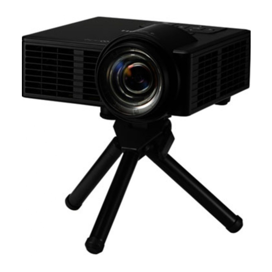
1. Product Information Overview Main Unit... - Page 8 1. Product Information 1. Control panel 2. Focus ring 3. Lens 4. Adjustable foot 5. Lens cap 6. Ventilation (inlet) 7. Infrared remote sensor 8. Connection ports 9. Ventilation (outlet)
-
Page 9: Control Panel
Overview Control Panel Ind. Part Name Description Power Turns the projector on/off. Temp LED Indicate the projector's temperature status. Error LED Indicate the projector's error status. Menu Press this key to launch the Onscreen display (OSD). Four Directional Use , , , or to select items or make adjustments to your Select Keys selection. -
Page 10: Connection Ports
1. Product Information Connection Ports 1. Anti-theft lock hole 2. Micro SD card slot 3. USB Type A terminal 4. DC IN plugged jack 5. Headphone jack 6. HDMI / MHL terminal 7. Computer In terminal... -
Page 11: Remote Control
Overview Remote Control Ind. Part Name Description Power Turns the projector on/off. Mutes/unmutes audio and/or video depending on the chosen mute AV Mute option in the OSD menu ("Setup" > "Advanced" > "Mute"). Turns the main menu on/off or returns to upper level in the menu Menu operations. - Page 12 1. Product Information Ind. Part Name Description Four Directional Uses to operate menu. Select Exit Returns to the previous page. Enter Confirms your section of items in menu system. Fast Forward Searches forward. Enlarge part of the screen image. Reduce the enlarged part of the Magnify +/- image.
-
Page 13: Specifications
Specifications Specifications Product Highlights • RICOH PJ WXC1110 is a portable data projector with Multimedia playback function & Office viewer native to deliver min. • 600 lumens with WXGA (1280*800) resolution & 1.5 Watts mono speaker. With expandable memory from micro SD card slot, it can display photo, video, music, PDF & Microsoft Office documents directly via embedded multimedia module. -
Page 14: General Specifications
1. Product Information General Specifications Item Description Dimensions W112.5 x D105 x H40.5mm (not including focus ring, rubber foot & protruding parts) (W x D x H) Weight < 460g • Auto-ranging: AC100–240V ±10%, 50–60Hz Power Supply • DC Output: 19V/3.42A, 65W (max.) Engine Platform 2nd Gen. -
Page 15: Computer Compatibility
Specifications Item Description • 0.43–3.44m (mechanical travel range); Throw Distance • 0.86–1.72m (optical travel range) • 25–200" (mechanical travel range) Image Size • 50–100" (optical travel range) optimize at 60" • Typical: 800:1 Contrast Ratio • Minimum: 600:1 Uniformity • Typical: 88% (JBMA standard) •... -
Page 16: Lens
1. Product Information PC (HDMI and VGA) and Macintosh compatible Mode Resolution Refresh rate [Hz] Notes for Mac 480i/480p 576i/576p HDMI, 720p 50/60 YPbPr(via VGA port) 1080i 50/60 1080p 24/50/60 *1 3D timing for TI DLP 3D *2 Down-scaling from 1024x768 to 800x600 to fit the front-end output specification, and then up- scaling into DPP6401 Lens F#1.9, F=8.02 mm (at 60"... - Page 17 Specifications Video Formats Decode Max. Max Bit Rate File Format Video Codec Audio Codec Profile Resolution (bps) 1920 x 1080 MPEG1 L1-3, MPG, MPEG MPEG1/2 30M bps LPCM 30fps BP(Baseline Profile)/ 1920 x 1080 AVI, MOV, MP(Main H.264 30M bps MP4, MKV Profile)/ 30fps...
- Page 18 1. Product Information Office Viewer Formats File Format Supported Version Page/Lines Limitation Size Limitation PDF 1.0, 1.1, 1.2, 1.3, Up to 360 pages (One Adobe PDF Up to 32 MB File) British Word 95 Because office viewer Up to 20 MB does not load all pages Word 97, 2000, of MS/Word file at the...
- Page 19 Specifications • (*) Row limit, column limit, and sheet limit can not appear in one Excel file simultaneously. • Animations are not supported when viewing MS PowerPoint files. • When projecting files, some documents may not be displayed the same as shown on the screen of a PC.
- Page 20 1. Product Information...
-
Page 21: Installation
2. Installation Installation Requirements Environment/Power Requirements Operating temperature 5°C to 40°C 20% to 80% humidity (no condensation) Power supply 100 to 240VAC ± 10%, 50 to 60Hz 19V/3.42A, 65W (Auto-ranging and DC Output) Machine Space Requirements Do not block projector in/out air vents. Leave at least the following space. Machine Dimensions 112.5 (W) x 105 mm (D) x 40.5 mm (H) (excluding protruding parts) -
Page 22: Main Machine Installation
2. Installation Main Machine Installation The user must set this projector up. • About the handling of this machine, follow the contents with reference to Safety Information in the user manual. Accessory Check... -
Page 23: Precautions
Main Machine Installation Description Q'ty Projector with lens cap Remote controller (CR2025 battery is included) AC adapter Power cord RGB cable CD-ROM (User's Guide) USB A to A cable Carry Bag Due to different applications in each country, some regions may have different accessories. Precautions •... - Page 24 2. Installation...
-
Page 25: Replacement
3. Replacement Equipment Needed 1. Screw Driver (+): No.00 2. Screw Driver (+): No.1 3. Screw Driver (-): 2.5mm 4. Projector... -
Page 26: Parts List
3. Replacement Parts List Service Parts List 1. FPC cable 2. Users guide (CD-ROM) 3. Quick start card (sheet) 4. Power cord 5. VGA cable 6. USB Type A to A cable 7. Remote controller 8. AC adapter 9. Focus ring 10. -
Page 27: Part Replacement
Part Replacement Part Replacement • Before you start: This process is protective level II. Operators should wear electrostatic chains. • If you need to replace the main board, you have to get into service mode and record the LED usage hour (page 41 "Service Mode "). Exterior Cover Top Cover Remove screws on the Bottom Cover (M1.6x5... - Page 28 3. Replacement Insert a flathead screwdriver from the area indicated by a blue circle and release the I/O cover’s hooks (indicated by red arrows). Open the I/O cover [A]...
-
Page 29: I/O Cover
Part Replacement Release the lock of the FPC [A], and disconnect the bottom of the FPC. Insert a flathead screwdriver under the top cover [A], remove 7 hooks (indicated by red arrows), and then remove the top cover [A]. I/O Cover Top cover (page... -
Page 30: Bottom Cover
3. Replacement Unplug one connector to remove the I/O cover ( x1). Bottom Cover Top Cover (page I/O Cover (page... - Page 31 Part Replacement Disconnect the connector ( Remove the Engine module with the Main board [A] (M1.6*4 x3). Bottom cover [B]...
-
Page 32: Speaker
3. Replacement • When installing the new bottom cover, be sure to apply a new dissipation sheet [A]. Speaker I/O Cover (page Speaker [A] (M2.0 x1). FPC Cable Top Cover (page... -
Page 33: Multimedia Board
Part Replacement FPC cable [A] Multimedia Board Top Cover (page FPC Cable (page... -
Page 34: Keypad
3. Replacement Multimedia Board [A] (4 1.6 x4). Keypad Top Cover (page Multimedia Board (page Keypad [A]... -
Page 35: Engine Module
Part Replacement Engine Module Bottom Cover (page Remove screws (M1.6*4 x3). -
Page 36: Fans
3. Replacement Engine Module with Focus Ring [A] Focus Ring [A] (M1.7*4 x3). Fans Engine Module (page... - Page 37 Part Replacement Fans [A]: Left Fan ( [B]: Front Fan ( [C]: Rear Fan ( • All fans are fastened by a double-sided adhesive tape. • Direction of the ventilation: See "page 5 "Main Unit"". • Route the Front Fan [B] cable through the back side of the board as shown below.
-
Page 38: Main Board
3. Replacement Main Board Engine Module (page Remove three fans ( x3). (page 34 "Fans") Main Board [A]... -
Page 39: Adjustable Foot
Part Replacement Adjustable Foot Adjustable foot [A]... - Page 40 3. Replacement...
-
Page 41: Adjustment
4. Adjustment Required Action after Replacing Parts After replacing parts, execute the related items shown in the table below. Changed parts Software Required Action Description page Multimedia Engine Main Board Firmware Board Module page 43 "ADC ADC calibration Calibration" page 47 Factory Reset "Factory Reset"... -
Page 42: Special Tools
4. Adjustment Special Tools Make sure that engineers are equipped with the following tools, which will be necessary in order to update the firmware, and to perform adjustments that are necessary after replacing the optical engine or main board. • RS232 cable (9-pin to 9-pin) •... -
Page 43: Service Mode
Service Mode Service Mode How to enter the Service Mode Turn on the projector. Press the "Power [1]", "Left [2]", "Left [3]", and "Menu [4]" keys sequentially. The service mode menu appears. • You can use the remote controller to enter the service mode in the same way. -
Page 44: Service Mode Settings
4. Adjustment • To exit from the service mode or return to the previous menu, select "Exit". Service Mode Settings Setting Item Description System Hours The projector’s cumulative time that it has been switched on. LED Hours The LED’s cumulative operation time. LED Hours (low) The LED’s cumulative operation time in low power mode. -
Page 45: Calibration
Calibration Calibration • If you don't have professional equipment such as Quantum Data 802B or Chroma 2327, please use a PC that supports HDTV resolution and has an independent graphic card to output the corresponding PC pattern. You can download the "test pattern by PC" from SERES as shown below. -
Page 46: Procedure
4. Adjustment • The calibration pattern should be in full screen mode. Procedure Project the test pattern. Get into the service mode. (page 41 "Service Mode ") Select "Analog Settings". Select "ADC Calibration". When the calibration has finished, "Success" appears. -
Page 47: Criteria
Calibration Execute "Factory Reset". (page 47 "Factory Reset") After the ADC Calibration, project the test Pattern (64 gray RGBW with 1280 X 800 @60HZ) and check the following criteria. 64 gray RGBW Criteria • The screen must appear normal, without abnormalities such as lines. (The unidentified color levels on both left and right sides should not be over 8 color levels.) •... - Page 48 4. Adjustment Select "G Sensor Calibration". • "G Sensor Calibration" must have a value; it must not be blank.
-
Page 49: Factory Reset
Factory Reset Factory Reset Factory Reset allows you to erase all OSD menu, restore the default setting, and clear the Failure Log. Factory Reset Procedure Get into the service mode (page 41 "Service Mode ") Select "Factory Reset". Select "Yes". When the factory reset has finished, "Success!!"... - Page 50 4. Adjustment...
-
Page 51: Troubleshooting
5. Troubleshooting Troubleshooting Main Procedure... -
Page 52: No Power Troubleshooting
5. Troubleshooting No Power Troubleshooting... -
Page 53: Power Troubleshooting
Troubleshooting Power Troubleshooting... -
Page 54: Image Performance Troubleshooting
5. Troubleshooting Image Performance Troubleshooting... - Page 55 Troubleshooting...
-
Page 56: Remote Control Troubleshooting
5. Troubleshooting Remote Control Troubleshooting... -
Page 57: Led Lighting Message
LED Lighting Message LED Lighting Message 1. Power LED 2. Temp LED 3. Error LED Power LED Power LED Temp LED Error LED Message Amber Blue Amber Amber Standby State Flashing (Input power cord) Power on & LED Steady light lighting Flashing Error (Fan failed) -
Page 58: Error Log
5. Troubleshooting Error Log Checking the Error Log Get into the service mode. (page 41 "Service Mode ") Select [Failure Log]. Check the error log information. Error Codes Error Form Description Indicates the projector was AC unplug No.[n] [System Hours] [Normal/Eco] [x] [x] powered off due to a power loss. - Page 59 Error Log Error Form Description Error log for fan failure. - Fan IDs - Fan lock No.[n] [System Hours] [Normal/Eco] [fan id] [x] Left Fan: 2 Front Fan: 3 Rear Fan: 1 Over Heat No.[n] [System Hours] [Normal/Eco] [temp.] [x] Error log for over temp.
- Page 60 5. Troubleshooting...
-
Page 61: Firmware Update
6. Firmware Update Overview of the Firmware Update There are two types of firmware as shown below. Perform their update individually. Update Firmware Function Description Procedure System OSD control, IR/ keypad input Main system page 60 Firmware processing, fan control, and so on. AM8250 Multi-media All Multi-media functions. -
Page 62: System Firmware Upgrade
6. Firmware Update System Firmware Upgrade Equipment Needed Software 1. DLP Composer Lite 11.2 2. Firmware file (*.img) 3. FlashDeviceParameters-20141125 Hardware 1. Projector 2. AC Adapter 3. Power Cord 4. USB Cable (USB type A to A) 5. PC • During FW upgrade procedure, please select "32KB" in "Skip Boot Loader Area". DLP Composer Lite Setup Procedure Choose "DLP Composer Lite V11.2 Setup"... - Page 63 System Firmware Upgrade Click "Next". Read "License Agreement". 1. Choose "I accept and agree to be bound by all the terms and conditions of this License Agreement". 2. Click "Next".
- Page 64 6. Firmware Update Click "Next". Click "Next". Click "Next".
-
Page 65: Firmware Upgrade Procedure
System Firmware Upgrade The program is being installed. Click "Finish". Firmware Upgrade Procedure Hold down the "Menu" key [A] then plug the DC [B] into the projector. - Page 66 6. Firmware Update When the "Power LED" lights purple, release the "Menu" key quickly. Connect the projector to the PC with a USB cable (USB type A to A). Execute "Install DLP Device Drivers" in the start menu. Select "Jungo WinDriver (WinXP), then click "Install".
- Page 67 System Firmware Upgrade Click "Next". Click "Finish". Execute the "DLP Composer(TM) Lite 11.2" file. Setting "FlashDeviceParameters". 1. Select the file "FlashDeviceParameters". 2. Put the "FlashDeviceParameters" file into the folder where you setup "DLP Composer Lite 11.2".
- Page 68 6. Firmware Update Select "Preferences" in the "Edit" menu. Click "Communications" [1]. - Select "USB" [2]. - Click "OK" [3].
- Page 69 System Firmware Upgrade Choose "Flash Loader" [1]. - Click "Browse" [2] to search the firmware file (*.img) [3]. - Click "Open" [4]. Select ‘Skip Boot Loader Area’. - Select "32KB". - Click "Reset Bus" to erase the flash memory.
- Page 70 6. Firmware Update Check the FW version. Re-connect the power cord and power on the projector. Get into the service mode (power--left-- left--menu) to check the system firmware version.
-
Page 71: Am8250 Firmware Upgrade
AM8250 Firmware Upgrade AM8250 Firmware Upgrade Equipment Needed Software 1. Firmware file (*.bin) 2. ActionsMPUUpdate.zip Hardware 1. Projector 2. AC Adapter 3. Power Cord 4. USB Type A to A Cable 5. PC USB Driver Upgrade Procedure Unzip the "ActionsMPUUpdate.zip" file. Hold down the "Menu"... - Page 72 6. Firmware Update When the "Power LED" lights purple, release the "Menu" key quickly, wait a minute, then press the "Menu" key again. The projector will power on. Connect the projector to the PC with a USB cable (USB type A to A). The found new hardware wizard will appear on the screen.
- Page 73 AM8250 Firmware Upgrade Select "Include this location in the search". Click "Browse" button to choose "ActionsMPUpdate". - Select "OK". - Then click "Next".
-
Page 74: Am8250 Firmware Upgrade Procedure
6. Firmware Update Click "Continue Anyway". Click "Finish" to end the installation. AM8250 Firmware Upgrade Procedure Open the "ActionsMPUpdate" folder. - Execute "ActionsMPUpdate.exe". - Page 75 AM8250 Firmware Upgrade Click "Update" [1]. - Click "Firmware" [2], - Select the FW upgrade file (*.Bin) [3]. - Click "Open" [4].
- Page 76 6. Firmware Update Click "Download." The success information will appear on screen.
- Page 77 AM8250 Firmware Upgrade Restart the unit and enter the service mode (power--left--left--menu) to check the AM8250 firmware version.
- Page 78 MEMO...
Need help?
Do you have a question about the WXC1110 Y0AB and is the answer not in the manual?
Questions and answers