
Subscribe to Our Youtube Channel
Related Manuals for Aquametro CONTOIL VZF II


Summary of Contents for Aquametro CONTOIL VZF II
-
Page 1: Table Of Contents
Mounting and operating instructions Page 3 – 47 ® CONTOIL DN15 - 50 VZF II / VZFA II Table of content 1 Safety 2 Product description 3 Installation 4 Operation 5 Maintenance and Repair 6 Troubleshooting 7 Decommissioning, Dismantling and Disposal 8 Technical Data 9 Appendix... - Page 2 CONTOIL® DN15 - 50...
-
Page 3: Safety
Safety 1.1 Intended Use ® The CONTOIL flow meter is designed and solely intended for the flow measurement of Diesel oil to Heavy Fuel Oil according to ISO 8217-2010 Improper or non-intended use may lead to the operational reliability of the device and is no longer guaranteed. - Page 4 1.3 Safety rules and precautionary measures The manufacturer accepts no responsibility if the following safety rules and precautions are disregarded. Modifications of the device implemented without preceding written consent from the manufacturer, will result in the immediate termination of product liability and warranty period.
-
Page 5: Product Description
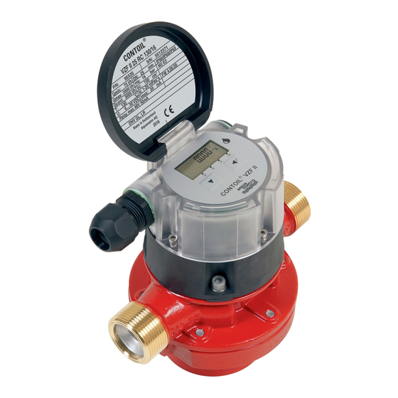
Product description 2.1 Scope of supply 1 Flow meter with electronic display unit. 1 mounting and operating instruction (this manual) 2.2 Flow meter configuration ® The CONTOIL flow meters consist of a hydraulic part, a coupling with temperature sensor included and an electronic display unit. The hydraulic part determines the nominal size of the flow meter. - Page 6 Costs incurred for waste disposal and injury (burns, etc.) due to inadequate declara- tion and/or cleaning will be charged to the delivering company or the operator. For a device that is sent back to Aquametro Oil & Marine AG for repair or calibration the fol- lowing point are an absolute must: ...
-
Page 7: Installation
Installation CAUTION The surfaces of the device/system and the medium may be hot. Risk of burns! Carry out work only on cooled devices/systems. Work may only be performed by authorized specialists in accordance with the applicable regulations. Use appropriate protective equipment. WARNING The device/system may be under pressure. - Page 8 The layout of piping must ensure that the flow meter is filled with liquid at all times and that no inclusions of air, foam or gas may occur. Aquametro Oil & Marine AG recommends to install bypass valves. Non-Return Flow meter...
- Page 9 Select the flow meter and ancillaries according to the working conditions listed below: Flow rate (maximum expected application flow rate = maximum continuous flow rate of flow meter Qcont) Material compatibility with medium Operating pressure and temperature ...
- Page 10 NOTICE The filter mounted in the flow meter inlet is only a safety filter and can not act as a dirt filter. Risk of malfunction or damage. If the medium contains dirt always have a dirt filter installed upstream of the flow meter . Heat insulation The electronic counter must not be insulated.
- Page 11 Special requirements - ships On ships, attention is required to ensure that the engine can continue to operate at full power even if there is heavy filter contamination or if the flow meter requires maintenance. A pressure switch can be used to switch over to the bypass and to draw attention for servicing. The engine then continues to operate but without consumption measurements.
- Page 12 Installation of the flow meter on the suction side of a pump If the flow meter is installed on the suction side of a pump, consideration must be given to avoid air-intake or foam. Filter Flow meter on suction side Pump Installation of the flow meter on the pressure side of a pump Filter...
- Page 13 3.2 Mechanical installation WARNING Leakage or rupture due to connections being made using force. Risk of severe injury! Risk of substantial property damage! Never attempt to overcome misalignments (lateral, angular, longitudinal, torsional) using force. Make sure the pipings are flexible enough, if not: use compensators. ...
- Page 14 CAUTION Unauthorized start-up while mounting. Risk of injury! Make sure that unauthorized start-up is not possible while mounting. Comply with the appicable working regulations during all work on the system. NOTE When existing systems are altered: Take the flow meter out of operation in order to flush the system clean of debris.
- Page 15 Meter with flanged ends Meter with threaded ends For pipes made of copper or thin-walled steel, the flow meter requires additional supports. Use appropriate fasteners. 3.3 Electrical Installation NOTICE Electrical connection to power supply and other systems. Risk of malfunction or damage ...
- Page 16 3.5 Mounting of electronic display unit NOTE The display can be rotated +/-270° in 90° steps during installation to improve readability. NOTICE Electrical connection to Pt1000 temperature sensor. Risk of malfunction or damage Ensure not to pinch cable while mounting electronic display unit onto coupling.
-
Page 17: Operation
Operation NOTE Modification of operation settings may result in faulty or wrong measuring results. Multiple output functions are available, any of these functions can be used simultaneously. 2 potential-free digital outputs (Out.1 + Out.2), each freely programmable The passive current loop is also used to power the flow meter at the same time. - Page 18 4.1 Commissioning Startup and commissioning of mechanical part of flow meter, without programming any electronic counter (VZF II and VZFA II). Open valves slowly, fill pipework gradually. Vent the installation well. Water hammer must be avoided in order not to damage the flow meter. Inclusions of air cause measuring errors in all types of flow meter and can damage them during operation.
- Page 19 4.2 Display and operation The display shows 8-digits with a decimal point or text messages using letters. Units of measurement and additional items of information are shown with symbols. The references to these are shown in square brackets, e.g. [o1VoLum]. actual value units Step key...
- Page 20 4.3 Parameterizing In order to adjust the parameters, scroll to the [SEtUP] item from the Main Menu and press the Enter key No code is required to view parameters. To adjust any parameter in the Seutp menu, the device must be unlocked ( ) with the user code.
- Page 21 Use the Step key to scroll through all the menu items, as follows: Visible when mass calculation is turned on: Mass tot Totalizer Mass Subtotalizer Mass Mass Subtot Mass flow (actual) Mass Flow Main Totalizers and displays Totalizer Totalizer Volume Subtotalizer Voume* Subtotal* Flow rate Volume or Norm-Volume...
- Page 22 4.5 Setup menu structure Setup Menu: shows settings for parameters, units and output signals. Unit vol L,m3,G Unit ti h,min,s Unit °t °C,°F Unit m kg,t,lb dn xx Mass off 15,20,25,40,50 Vc x.xx per dn Oil Fuel Oil Lube Trip res yes / no °t Limit LFC xx.xx...
- Page 23 o1 State o1 Off o2 Limit o2 State o2 Off 5 Qmax hidden with user code view only Standard Volume Compensation visible when Mass Calc is on CONTOIL® DN15 - 50...
- Page 24 4.6 Output assignment settings Use Step key to scroll through output 1 / 2 options (volume, flow / frequency, mass, mass flow, limit, state and off). Technical output specifications can be found on page 37. Output 1 settings o1 Volume Sim off Si value o1 Flow...
- Page 25 Act Pulse Err FMA Sim off Si value Act __ Hz Act Pulse Err FMA Sim off Si value Act __ Hz Sim off Si value Activ Act Pulse Err FMA Sim off Si value Act __ Hz Act Pulse Err FMA Sim off Si value...
- Page 26 4.7 Description of menu items As they appear in the menu structure Possible parameter units are described on page 44 Main Menu Mass Tot totalizer of mass flow in selected units Mass Subtot subtotalizer of mass flow Mass Flow mass flow Totalizer main totalizer of volume flow Subtot...
- Page 27 Used rng Range where the counter been used in hours (h) Total hours of operation (h) hours of operation in preferred range (Qmin – Qcont) hour of operation in upper flow range (Qcont – Qmax) hours of operation above Qmax (h) duration since last recorded flow (h) maximum registered flow rate since start of operation U Code*...
- Page 28 Outputs see Technical output specifications on page 37 for more details oX = o1 or o2 oX Volume select when volume pulses are required (digital pulse) oX Flow select when flow is required (frequency) oX Mass select when mass pulses are required (digital pulse) oX mFlo select when mass flow is required (frequency) oX Limit...
-
Page 29: Maintenance And Repair
5.1 Calibration All our flow meters are calibrated in the factory. An accuracy check and recalibration is offered at Aquametro Oil & Marine AG, this is usually dependent on customer, operator or regulation requirements. This interval depends largly on the operating conditins, process liquid and the application the flow meter is installed in. - Page 30 Cleaning of flow meter: do not use any aggressive solvents rinse hydraulic part of flow meter thoroughly Aquametro Oil & Marine AG recommends to use the following cleaning solvents: Gasoline used for cleaning purposes Cleaner’s naphtha ...
- Page 31 NOTICE Use of wrong Spare parts Risk of malfunction or damage Use only original spare parts, supplied by Aquametro Oil & Marine AG Spare part list and Maintenance instructions VI14-419 may be requested from Aquametro Oil & Marine AG.
-
Page 32: Troubleshooting
Troubleshooting ® 6.1 For all CONTOIL flow meter Fault symptoms Possible causes Procedures No reading / blank No power supply Check wiring, polarity Electronic counter Replace electronic counter display defective Mention SN during order Counter not running ... - Page 33 6.2 Error messages VZF II / VZFA II The electronic module performs a self-test about every 5 minutes. If an error is detected which impairs the reliability or accuracy of the measurement, [ERROR] message will appear every 2 seconds on the display. Error messages are messages from the electronic module.
- Page 34 6.3 Alarm messages VZF II / VZFA II The electronic module performs a self-test about every 5 minutes. If an alarm condition is detected, [ALARM] message will appear on the display every 2 seconds. Alarm messages are messages from the parameter settings [nO ALmS] no alarm is active Action: none.
-
Page 35: Decommissioning, Dismantling And Disposal
Decommissioning, Dismantling and Disposal CAUTION The surfaces of the device/system and the medium may be hot. Risk of burns! Carry out work only on cooled devices/systems. Work may only be performed by authorized specialists in accordance with the applicable regulations. ... -
Page 36: Technical Data
Technical Data 8.1 Hardware characteristics Hydraulics Type VZF(A) II VZF(A) II VZF(A) II VZF(A) II VZF(A) II Nominal diameter inch 11/2 Installation length Nominal pressure with threaded ends with flanges 25 / 40 25 / 40 25 / 40 25 / 40 25 / 40 Maximum temperature Tmax °C 130, 180... - Page 37 Digital output (terminal 3-4, 5-6) Output (Out1 & Out2): 2 potential-free contacts Max. voltage Umax: 48VAC/VDC Max. current Imax: 50mA Max. output freq. fmax: 200Hz Update interval: <1ms ON-resistance R0 : ≤50Ω OFF-resistance R∞: ≥10MΩ...
- Page 38 Flow / Frequency output Setup menu: function for Output1 or Output2 Frequency range and proportionality of the signal across desired flow rate temperature measurement range Q1/T1 - Q2/T2 Signal behavior: If the flow falls below the set lower flow rate value, a proportional decrease to 0Hz will occur, which is then maintained until the flow rises over the lower flow rate again.
- Page 39 Limiting output Setup menu: function for Output1 or Output2 Flow The function Limit allows you to set an alert whenever rate active predefined flow rates are exceeded. Q Lim Hysteresis % of Q Lim Signal behavior: inactive inactive Limit defines upper (Q Lim ) and lower (Q Lim ) flow active...
- Page 40 State output according to signal faults Setup menu: function for Output1 or Output2 Whenever an error or an alarm occurs, you can send it Work State with this selected output. Any fault (Error, Alarm or power loss) can be sent to a active remote control or alarm system.
- Page 41 Analog current loop (4...20mA) Setup menu: Analog current loop The current signal is proportional to the flow rate or temperature range of Q1/T1 to Q2/T2 20.0 Signal behavior: when a relevant flow meter error occurs: Value falls below the set lower flow rate / temperature value Q1/T1: proportional decrease to 3.8mA which is then maintained.
- Page 42 8.3 Dimensional drawings Flow meters All flow meters with threaded ends are according to ISO 228-1 DN15, 20, 25: with threaded ends DN40: with threaded ends All flow meters with flanges are according to EN 1092-2, ASME B16.5 or JIS B2220 DN15, 20, 25: with flanged ends DN40, 50: with flanged ends Nomial size...
- Page 43 Dimensions of electronic counter VZF(A) II Dimensional drawing VZF II / VZFA II 8.4 Display of electronic counter VZF II / VZFA II CONTOIL® DN15 - 50...
- Page 44 8.5 Default settings VZF II / VZFA II Total counter mass unit selected in Unit volume Trip counter mass unit selected in Unit volume Actual mass flow unit selected in Unit volume and Unit time Total counter unit selected in Unit volume Trip counter unit selected in Unit volume Actual flow...
- Page 45 Mass output Pulse width 50ms, 2...500ms Unit per pulse 1UPP, 0.001...1000UPP [0.1UPP...DN15] Simulation off, on 0…Qmax (max. 9999.9) Sim value Actual output display flashes [Act Pulse] when active Mass Flow output Min Flow Qmin, 0...Qmax Min Frequency 20Hz, 1...200Hz Max Flow Qcont, 0...Qmax Max Frequency 200Hz, 1...200Hz...
- Page 46 Analog Output Temperature disabled, enabled Min Value 20, 0...Tmax Max Value 100°C / 212°F, 0...Tmax (Tmax = 200°C / 392°F) tAU value 4, 0...9 Error behavior act, High, Low Simulation off, on 0…Qmax (max. 9999.9) Sim value Actual output displays actual current on output [Act mA] when active Analog Output Mass Flow disabled, enabled Min Value...
-
Page 47: Appendix
Appendix 9.1 Certificates All the below mentioned certificats / approvals, can be found on our web site www.aquametro-oil-marine.com Marine approval classifications Det Norske Veritas Norway - Germany - German Lloyd Lloyds Register United Kingdom Versions with type approval and metrological CE approval ®... - Page 48 Aquametro Oil & Marine AG Aquametro Oil & Marine GmbH CH-4106 Therwil, Switzerland DE-18119 Rostock, Germany info@aquametro-oil-marine.com info@aquametro-oil-marine.com www.aquametro-oil-marine.com Phone +41 61 725 44 00 Phone +49 381 382 530 00...
Need help?
Do you have a question about the CONTOIL VZF II and is the answer not in the manual?
Questions and answers