
Related Manuals for Waveshare NRF52840


Summary of Contents for Waveshare NRF52840
- Page 1 NRF52840 Eval Kit User Manual NRF52840 Eval Kit User Manual Vision: V1.0.1 Date: 2019.01.19 1 / 72...
-
Page 2: Table Of Contents
NRF52840 Eval Kit User Manual CONTENT Chapter 1. Overview ..........................5 what’s on Board ..........................5 Chapter 2. Setup Developing Environment ..................7 Install Keil and related Pack ......................7 Install SEGGER Embedded Studio for ARM 4.10a ..............7 Serial driver install ..........................7 Install Jlink driver ..........................8 Install nRFx-Command-Line-Tools ....................9... - Page 3 NRF52840 Eval Kit User Manual Hardware ............................27 Chapter 6. SPI ............................29 Loopback testing ..........................29 Drive OLED ............................30 Hardware ............................31 Chapter 7. I2C ............................33 Scanning Slave devices ......................... 33 Read data from BME280 ......................33 Read data from MPU6050 ......................
- Page 4 NRF52840 Eval Kit User Manual Bluetooth Master- Cardiotachometer ..................56 Master-Slaver-BLE Relay ......................58 Chapter 10. MESH ........................... 62 Vision: V1.0.1 Date: 2019.01.19 4 / 72...
-
Page 5: Chapter 1. Overview
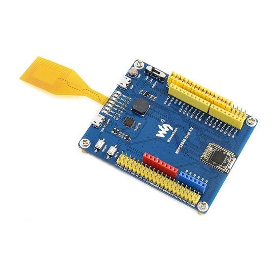
NRF52840 Eval Kit User Manual CHAPTER 1. OVERVIEW NRF52840 Eval Kit is a development/evaluation kit based on nRF52840, features Arduino / Raspberry Pi connectivity, and several common peripherals. It supports the new generation Bluetooth 5.0, compared to Bluetooth 4.0, the data rate is twice, up to 2Mbps, the transfer distance is quadruple. - Page 6 LED1~LED4: USER LEDs connecting Raspberry Pi HATs 14. Power switch USB TO UART interface USB: powered from USB connection USB port: the USB port of nRF52840 Battery: powered from CR2032 4PIN SWD debugging interface: battery for connecting ARM Debugger to 15.
-
Page 7: Chapter 2. Setup Developing Environment
Generally, we use nRFgo Studio software to programming NRF52840, however, because of the compatibility of JLink driver, which is the driver of programmer of nRF series. Herein we use CLI to setup developing environment for nRF52840 instead of nRFgo Studio. -
Page 8: Install Jlink Driver
Computer->Manager->Devices Manager-> COM and LPT after you connect the evaluation board to PC. INSTALL JLINK DRIVER JLink programmer is used to programming NRF52840. It can also be used to erase NRF52840Flash and upload Bluetooth Softdevices with nRF5x-Command-Line-Tools. We recommend you use V6.22 version or above, otherwise, the driver may cannot be recognized. -
Page 9: Install Nrfx-Command-Line-Tools
NRF52840 Eval Kit User Manual INSTALL NRFX-COMMAND-LINE-TOOLS The tool can be downloaded from resources. Download and install it. After installing, open console, and input nrfjprog -v to check the tools. It should be as below if you install the tool successfully. -
Page 10: Peripherals Demo
HARDWARE CONNECTION Connect J-Link programmer to NRF52840 Eval kit and PC ⚫ Connect NRF52840 Eval Kit to PC or other external power adapter ⚫ Pull the jumper of LED3, and wire L3 to P1.05 ⚫ LED3 isn’t compatible with official SDK, so we should re-connect it when test Blinky sample Vision: V1.0.1 Date: 2019.01.19... -
Page 11: Download Samples Without Softdevice
NRF52840 Eval Kit User Manual DOWNLOAD SAMPLES WITHOUT SOFTDEVICE We take Blinky as example, learn how to use peripherals examples of SDK. Click blinky->pca10056->blank->arm5_no_packs->blink_pca10056.uvoptx to open the project. Compiling it: Generally, it can be compiled successfully without error or warning. After compiling, you should configure it: Click Debug, choose J-Links/J-Trace Cortex as debugger. - Page 12 NRF52840 Eval Kit User Manual Then click Flash Download, check the options as below and confirm by clicking Vision: V1.0.1 Date: 2019.01.19 12 / 72...
-
Page 13: Download Samples With Softdevoce
Bluetooth demo codes are based on. Herein we take app_uart as example to show you how to program such demos. First, we need to erase NRF52840 flash: Open CMD, connect NRF52840 to PC and ⚫ using ARM Debugger(JLink) for programming. Type command to erase NRF52840 Vision: V1.0.1 Date: 2019.01.19... - Page 14 NRF52840 Eval Kit User Manual as below: Download Softdevice. Click ⚫ nRF5_SDK_15.2.0_9412b96->examples->ble_peripheral->ble_app_uart->pca10056 ->s140->arm5_no_packs-> ble_app_uart_pca10056_s140.uvprojx to open the project. Choose flash_s140_nrf52_6.1.0_softdevice: Download the application code like blinky sample. ⚫ Vision: V1.0.1 Date: 2019.01.19 14 / 72...
-
Page 15: Chapter 3. Creating New Project
NRF52840 Eval Kit User Manual CHAPTER 3. CREATING NEW PROJECT SDK should be used for NRF52840 developing, we take common SDK as example to show you how to create a project. The SDK used herein is SDK V15.2, there is also template for reference: nRF5_SDK_15.2.0_9412b96\examples\ble_peripheral\ble_app_template\pca10056\s140... -
Page 16: Create A New Project
NRF52840 Eval Kit User Manual There are so many files included in SDK, and we only use some of them for certain project. Most of libraries are included in components, external contains third party libraries like freertos library and so on. Old drivers are saved to folder integration and modules contains the new drivers. - Page 17 NRF52840 Eval Kit User Manual The drivers of user peripherals should be saved in DRIVER folder ⚫ The projects created should be saved under USER, and please notice the project ⚫ name The application files are usually saved under the path: USER/[Project ⚫...
- Page 18 NRF52840 Eval Kit User Manual The Keil project file is saved in IDE folder ⚫ Save OBJ files to TEMP folder ⚫ Vision: V1.0.1 Date: 2019.01.19 18 / 72...
- Page 19 NRF52840 Eval Kit User Manual You had better set the project tree same as official projects. ⚫ Notice the PACK version you use, make sure it is same as official examples ⚫ For more details, please refer to official examples.
-
Page 20: Chapter 4. Controling Led
NRF52840 Eval Kit User Manual CHAPTER 4. CONTROLING LED In this chapter, we will instruct how to configure GPIO and control LED. The examples used herein is 001_LED. CODES Open led.h files, you can find that the GPIO and related control functions are defined... -
Page 21: Hardware Connection
NRF52840 Eval Kit User Manual And finally, the functions are called in main file to keep turning four LEDs on for 500ms then turning them off for 500ms. main(void) while (true) LED_On(LED0); LED_On(LED1); LED_On(LED2); LED_On(LED3); nrf_delay_ms(500); LED_Off(LED0); LED_Off(LED1); LED_Off(LED2); LED_Off(LED3);... - Page 22 NRF52840 Eval Kit User Manual The schematic of Eval board is as below: Header 4x2 are jumpers on board: If you use official SDK, don’t forget to pull L3 jumper and wire it to P0.15 (Do not require if you use 001_LED).
-
Page 23: Chapter 5. Uart
NRF52840 Eval Kit User Manual CHAPTER 5. UART In this chapter, we describe about how to use UART interface of NRF52840. The example used herein is 003_UART. With the example, data can be sent from NRF52840 to UART interface, and LED on eval board will turn on/off when receive corresponding data from UART interface. - Page 24 NRF52840 Eval Kit User Manual app_uart_comm_params_t comm_params RX_PIN_NUMBER, TX_PIN_NUMBER, RTS_PIN_NUMBER, CTS_PIN_NUMBER, UART_HWFC, false, NRF_UART_BAUDRATE_115200 void uart_error_handle(app_uart_evt_t * p_event) (p_event->evt_type == APP_UART_COMMUNICATION_ERROR) APP_ERROR_HANDLER(p_event->data.error_communication); else if (p_event->evt_type == APP_UART_FIFO_ERROR) APP_ERROR_HANDLER(p_event->data.error_code); main.c: #include "nrf.h" #include <stdio.h> #include <stdint.h> #include <stdbool.h> #include "app_uart.h" #include "app_error.h"...
- Page 25 NRF52840 Eval Kit User Manual uint32_t err_code; APP_UART_FIFO_INIT(&comm_params,UART_RX_BUF_SIZE,UART_TX_BUF_SI ZE,uart_error_handle,APP_IRQ_PRIORITY_LOWEST,err_code); APP_ERROR_CHECK(err_code); printf("\r\nUART example started.\r\n"); while (true) uint8_t //Get Data from the port! while (app_uart_get(&cr) != NRF_SUCCESS); //Then put data to the port while (app_uart_put(cr) != NRF_SUCCESS); switch (cr) case '1': printf("\r\n LED0 ON \r\n");...
- Page 26 NRF52840 Eval Kit User Manual printf("\r\n LED2 ON \r\n"); LED_On(LED2); break; case '6': printf("\r\n LED2 OFF \r\n"); LED_Off(LED2); break; case '7': printf("\r\n LED3 ON \r\n"); LED_On(LED3); break; case '8': printf("\r\n LED3 OFF \r\n"); LED_Off(LED3); break; case 'q': printf("\r\n Exit! \r\n");...
-
Page 27: Hardware
When 1 is received, LED1 is on, and turned off if receiving 2. Turn LED2 on if 3 and turn off if 4 similarly. HARDWARE The schematic of serial part is as below: H1 and H2 are jumpers of UART pins. CP2102 is accessed to NRF52840 only when jumpers H1 and H2 are inserted. UART GPIO CPTX P0.06... - Page 28 NRF52840 Eval Kit User Manual 【Note】In official SDK, CPRTS is defined as P0.05, however, CPRTS is connected to P0.25 on NRF52840 Eval kit. You need to modify the definition to P0.25 when using. Vision: V1.0.1 Date: 2019.01.19 28 / 72...
-
Page 29: Chapter 6. Spi
NRF52840 Eval Kit User Manual CHAPTER 6. SPI Examples used in this chapter: 004_SPI(Example), 005_SPI(OLED) In this chapter, we will describe about how to use SPI interface of NRF52840, do loopback testing and try to drive a 0.96inch OLED module. LOOPBACK TESTING main.c... -
Page 30: Drive Oled
NRF52840 Eval Kit User Manual NRF_LOG_INFO("SPI example started."); NRF_LOG_FLUSH(); while memset(m_rx_buf, 0, m_length); spi_xfer_done = false; APP_ERROR_CHECK(nrf_drv_spi_transfer(&spi, m_tx_buf, m_length, m_rx_buf, m_length)); while (!spi_xfer_done) __WFE(); NRF_LOG_FLUSH(); nrf_delay_ms(500); DRIVE OLED When you drive OLED via SPI interface, you should notice that: 1. Do not use interrupt callback function when initializing SPI Doesn't print what to send or what received in SPI //APP_ERROR_CHECK(nrf_drv_spi_init(&spi, &spi_config, NULL,... -
Page 31: Hardware
//if SPI is busy Frequently,delay here //nrf_delay_us(30); spi_write(&cmd, sizeof(cmd)); read void Single_Data(unsigned char nrf_gpio_pin_set(DC); //if SPI is busy Frequently,delay here //nrf_delay_us(30); spi_write(&dt, sizeof(dt)); HARDWARE In hardware, the SPI interface of NRF52840 are pinout to Arduino compatible interface. Vision: V1.0.1 Date: 2019.01.19 31 / 72... - Page 32 NRF52840 Eval Kit User Manual 【Note】The pins used in example herein are different with official SDK, if you use official SDK with NRF52840 Eval Kit, don’t forget to modify the pins GPIO SPI_CS P1.12 SPI_MOSI P1.13 SPI_MISO P1.14 SPI_SCK P1.15 Loopback testing Data will be sent from MOSI and back from the MISO.
-
Page 33: Chapter 7. I2C
NRF52840 Eval Kit User Manual CHAPTER 7. I2C In this chapter, we will learn about how to use the I2C interface of NRF52840. There are three examples, which are used here: 006_I2C(Scan Device), 007_I2C(BME280), 008_I2C(MPU6050 3D COUBE) SCANNING SLAVE DEVICES It keeps scanning the slave device address of those devices which are connected to I2C bus. - Page 34 NRF52840 Eval Kit User Manual int8_t rslt = 0; /* Return 0 for Success, non-zero for failure * The parameter dev_id can be used as a variable to store the I2C address of the device * Data on the bus should be like...
- Page 35 NRF52840 Eval Kit User Manual * |------------+---------------------| return rslt; Working with NRF52840, you can use its library to realize the write/read function: int8_t user_i2c_read(u8 dev_id, reg_addr, *reg_data, len) ret_code_t err_code nrf_drv_twi_tx(&m_twi,dev_id,®_addr,1,false); APP_ERROR_CHECK(err_code); err_code = nrf_drv_twi_rx(&m_twi,dev_id,reg_data,len); APP_ERROR_CHECK(err_code); return err_code; #define MAX_WRITE_LENGTH 200...
- Page 36 NRF52840 Eval Kit User Manual BME280 Initialization in main.c struct bme280_dev dev; int8_t rslt = BME280_OK; dev.dev_id = BME280_I2C_ADDR_SEC; dev.intf = BME280_I2C_INTF; dev.read = user_i2c_read; dev.write = user_i2c_write; dev.delay_ms = user_delay_ms; //before you init bme280, you can choose to do a selftest rslt = bme280_crc_selftest(&dev);...
-
Page 37: Read Data From Mpu6050
NRF52840 Eval Kit User Manual READ DATA FROM MPU6050 This example is run to read MPU6050 data via I2C bus. u8 IIC_Write_1Byte(u8 SlaveAddress,u8 REG_Address,u8 REG_data) ret_code_t err_code = user_i2c_write(SlaveAddress, REG_Address, ®_data, 1); return err_code; u8 IIC_Read_1Byte(u8 SlaveAddress,u8 REG_Address,u8 *REG_data) ret_code_t err_code = user_i2c_read(SlaveAddress, REG_Address, REG_data, 1);... -
Page 38: Hardware
NRF52840 Eval Kit User Manual HARDWARE In hardware, the I2C interface are pinout to the Arduino compatible header. GPIO SCL_PIN P0.27 SDA_PIN P0.26 The I2C pins can be re-configured to others by modifying the codes: #define SDA_PIN NRF_GPIO_PIN_MAP(0,26) #define SCL_PIN NRF_GPIO_PIN_MAP(0,27) 【Note】Don’t forget to change hardware connection if you re-configure the pins. - Page 39 NRF52840 Eval Kit User Manual Downloading 007_I2C(BME280) codes, data will be printed to OLED as below: ⚫ Vision: V1.0.1 Date: 2019.01.19 39 / 72...
- Page 40 NRF52840 Eval Kit User Manual Downloading 008_I2C(MPU6050 3D COUBE), Data will be printed as below(The 3D ⚫ figure display is not stable): Vision: V1.0.1 Date: 2019.01.19 40 / 72...
-
Page 41: Chapter 8. Nfc
NRF52840 Eval Kit User Manual CHAPTER 8. NFC CODES This example is used to starting mobile APP. The name of Android Phone APP: static const uint8_t m_android_package_name[] = {'n', 'o', '.', 'n', 'o', 'r', 'd', 'i', 'c', 's', 'e', 'm', 'i', '.', 'a', 'n', 'd', 'r', 'o', 'i', 'd', '.', 'n', 'r', 'f', 't', 'o', 'o', 'l', 'b',... - Page 42 NRF52840 Eval Kit User Manual In main.c file, the process to start NFC are that: 1. Set interrupt callback function and initialize NFC: 2. Encode NFC information 3. Load NFC information to NFC end 4. Start NRF main(void) uint32_t len;...
-
Page 43: Hardware
NRF52840 Eval Kit User Manual HARDWARE The pins for NFC are compatible with official GPIO NFC_1_PIN P0.09 NFC_2_PIN P0.10 Testing: Install nRF Toolbox APP in your phone. Connect NFC coils and download the codes to eval board. LED1 will be on if you close NFC side of phone to the NFC coils, and turn... -
Page 44: Chapter 9. Bluetooth
NRF52840 Eval Kit User Manual CHAPTER 9. BLUETOOTH The examples used in this chapter are: Part-2-Bluetooth-Slave-Device,Part-3- Bluetooth-Master-Device,Part-4-Bluetooth-Master&Slave-Device. PREPARATION The software required: MDK5.25 ⚫ Jlink driver ⚫ nRFx-Command-Line-Tools ⚫ nRF Toolbox (mobile APPP) ⚫ Mobile phone which supports BLE ⚫ INSTALL SOFTDEVICE To run the examples, you need to first install Softdevice. - Page 45 NRF52840 Eval Kit User Manual Open nRFToolbox software in your phone and enter UART, Connect Nodic_UART device After connecting, LED1 is on ⚫ You can edit the figures and try to send: ⚫ Vision: V1.0.1 Date: 2019.01.19 45 / 72...
- Page 46 NRF52840 Eval Kit User Manual You can also send data directly on Show log: ⚫ Vision: V1.0.1 Date: 2019.01.19 46 / 72...
-
Page 47: Bluetooth Against Losing
NRF52840 Eval Kit User Manual BLUETOOTH AGAINST LOS ING Download: Open the project SlaveDevice-Bluetooth-Proximity (APP), which located in Part-2- ⚫ Bluetooth-Slave-Device\USER Compile and download to eval board ⚫ Expected result: LED1 is lighted in when broadcasting after downloading ⚫ Turn on Bluetooth service of your phone ⚫... - Page 48 NRF52840 Eval Kit User Manual Open nRF Toolbox and clock UART. Connect Nordic_UART device ⚫ After connecting, LED1 will light on. The Toolbox will display as below: ⚫ Vision: V1.0.1 Date: 2019.01.19 48 / 72...
-
Page 49: Bluetooth Beacon (Support Wechat Shake)
NRF52840 Eval Kit User Manual You can click the indicator button on APP to control P0.15 pin of Eval Kit board. ⚫ When testing, you can connect P0.15 to one LED to check the status. Click Delete button to delete device. - Page 50 NRF52840 Eval Kit User Manual Open the project SlaveDevice-Bluetooth-BEACON(WeChat) which located in Part- ⚫ 2-Bluetooth-Slave-Device\USER Compile and Download to Eval Kit Board ⚫ 【Note】The example is different with official examples(line 74-77) APP_COMPANY_IDENTIFER change to:0X004c APP_MAJOR_VALUE change to:0x00,0x0A APP_MINOR_VALUE change to:0x00,0x07...
- Page 51 NRF52840 Eval Kit User Manual Click Nearby and try to shake ⚫ 【Note】The Web page detected is configurable, for more details about it you can refer to official guide of WeChat: https://zb.weixin.qq.com/intro.xhtml The testing ID used in the example is the open ID of WeChat...
-
Page 52: Wireless Mouse
NRF52840 Eval Kit User Manual WIRELESS MOUSE HOGP profile (HID over GATT Profile) can be used to release wireless mouse function. HOGP use basic protocol GATT of BLE to release interaction between HID host and Device. Download: Open the project SlaveDevice_bluetooth-HIDS_MOUSE(APP), ⚫... -
Page 53: Wireless Keyboard
NRF52840 Eval Kit User Manual P0.12 KEY2(up) Mouse move up for 5 pixels P0.24 KEY3(right) Mouse move right for 5 pixels P0.25 KEY4(down) Mouse move down for 5 pixels If your PC support BLE, you can also used to control cursor on PC ⚫... - Page 54 NRF52840 Eval Kit User Manual Download: Open the project SlaveDevice_bluetooth-HIDS_KEYBOARD(APP), ⚫ Compile and download to Eval Kit board. ⚫ Expected result: Eval Kit board broadcast and LED1 is blinking. ⚫ Open Bluetooth of your Phone, search and connect Nordic_keyboard device. After ⚫...
-
Page 55: Cscs
NRF52840 Eval Kit User Manual CSCS NRF52840 will send seed, rate, riding distance, total distance and gear ratio data to phone via BLE. The data is generated by software (simulated), which is based on Cycling Speed and Cadence profile. Download: Open the project Bluetooth-CSCS(APP), ⚫... -
Page 56: Bluetooth Master- Cardiotachometer
NRF52840 Eval Kit User Manual BLUETOOTH MASTER- CARDIOTACHOMETER You need two NRF52840 Eval Kit for this example, one is used as master, and another is slaver. Download: Open project Master-Link-To-Slave-By-HRS(Master), compile and download it to ⚫ one Eval Kit board. - Page 57 NRF52840 Eval Kit User Manual Expected result: The communication between two Eval Kit boards is as below: ⚫ After downloading, the master will auto-link to slaver, LED1 are on if they connect ⚫ successfully. Slaver will send data to Master, which are transferred to serial port and printed in ⚫...
-
Page 58: Master-Slaver-Ble Relay
NRF52840 Eval Kit User Manual MASTER-SLAVER-BLE RELAY With this example, Eval Kit board can work as master and slaver at the same time. Eval Kit board auto connect to another slaver (RSCS) when work as master ⚫ Eval Kit board will connect to phone when work as slaver ⚫... - Page 59 NRF52840 Eval Kit User Manual 【Note】 The slaver project is RSC project, it also can be HRM project Expected result: Power on Relay board, it begins to scan devices(master) and broadcasts(slaver). ⚫ LED1 and LED3 are on Power on Sensor board, it begin to broadcast and LED1 is blinking, LED1 stay on if ⚫...
- Page 60 NRF52840 Eval Kit User Manual Indicator of Sensor board: Indicator Description LED1 Blinking: Broadcasting On: Connected Open nRF Toolbox on phone, click RSC and Connect to nRF Relay device. ⚫ After connecting, LED2 of Relay board is turned off and LED4 turns on. Data are ⚫...
- Page 61 NRF52840 Eval Kit User Manual Vision: V1.0.1 Date: 2019.01.19 61 / 72...
-
Page 62: Chapter 10. Mesh
NRF52840 Eval Kit User Manual CHAPTER 10. MESH This chapter we describe some of the basic concepts of the Bluetooth Mesh network using Nordic’s nRF5 SDK for Mesh. The project we used herein is light-switch example from Nordic’s MESH SDK, for more details about it, you can refer to official Documents. - Page 63 NRF52840 Eval Kit User Manual Server: ⚫ During provisioning process: ◼ LED3 and 4 blinking: Device identification active ◆ LED1 to 4: Blink four times to indicate provisioning process is ◆ completed After provisioning and configuration is over: ◼ LED1: Reflects the value of OnOff state on the server ◆...
- Page 64 NRF52840 Eval Kit User Manual Button 4: Send a message to the even group (address: 0xC002) to ◆ turn off LED1. Provisioner: ⚫ Button1: Start provisioning ◼ LED1: Reflects the state of the provisioning. ◼ LED ON: provisioning of the node is in progress ◆...
- Page 65 NRF52840 Eval Kit User Manual Hardware requirement: it required at least three NRF52840 Eval Kit: One Eval Kit board for server ⚫ One Eval Kit board for client ⚫ One Eval Kit board for provisioner ⚫ Software requirement: 1. nRF Mesh SDK: nrf5_SDK_for_Mesh_v2.2.0_src, download and extract the SDK 2.
- Page 66 【Note】All the resources should be extracted to the same path, for linked by compiler. Otherwise, the project is failed to compile. Download: Connect NRF52840 Eval Kit board to PC. Decide which board you want to use as ⚫ client and which one as provisioner Open projects with SEGGER Embedded Studio for ARM 4.10a...
- Page 67 NRF52840 Eval Kit User Manual Compile projects ⚫ Download projects ⚫ You can also try to debug ⚫ Vision: V1.0.1 Date: 2019.01.19 67 / 72...
- Page 68 NRF52840 Eval Kit User Manual Running example: When the flashing is complete, the script executes a reset operation to start the example applications. After the reset, the provisioner waits for user input. Follow these steps to see the mesh network in actions: 1.
- Page 69 NRF52840 Eval Kit User Manual Press Button2 on the client board to turn OFF LED1 on all servers with ODD addresses iii. Press Button3 on the client board to turn ON LED1 on all servers with EVEN address Press Button4 on the client board to turn OFF LED1 on all servers...
- Page 70 NRF52840 Eval Kit User Manual User Phone as provisioner Besides the NRF52840 board, you can also use your phone as provisioner. 1. Download client and server project to Eval Kit board respectively. 2. Install nRF Mesh APP to your phone to work as a provisioner.
- Page 71 NRF52840 Eval Kit User Manual Client: The light switch client implements a Generic OnOff client. Together with light switch server and mesh provisioner, it is part of the light switch example network demonstration, in which it has a provisioner role.
- Page 72 NRF52840 Eval Kit User Manual client and mesh provisioner. There can be one or more servers in this network, for example light bulbs. The provisioner configures this server model instance to communicate with the client model. Vision: V1.0.1 Date: 2019.01.19...
Need help?
Do you have a question about the NRF52840 and is the answer not in the manual?
Questions and answers