
Subscribe to Our Youtube Channel
Related Manuals for CompAir L07


Summary of Contents for CompAir L07
- Page 1 User Manual Screw Air Compressor L07-L22 ● ● ● Id. Nr. 100013552 / 00 - Dezember 2007...
- Page 3 Genuine CompAir parts will be used. Warranty The conditions of the CompAir Warranty are set out in the Company’s standard Conditions of Sale available from the CompAir Company or Distributor supplying the machine. USE ONLY COMPAIR GENUINE PARTS. YOUR WARRANTY COULD BE AFFECTED IF A SERVICE OR REPAIR IS CARRIED OUT USING NON-GENUINE PARTS.
- Page 4 Data sheet for users *) The values on the type plate are maximum values. Your CompAir distributor Name: Address: ______________________________________________________________________________________ ______________________________________________________________________________________ ______________________________________________________________________________________ Telephone: Fax: Contact: Spare Parts: Service:...
-
Page 5: Foreword
1. Foreword For ew or d In addition, Notes on the compressor • relevant accident prevention regulations, CompAir screw compressors are the result of many • generally recognized safety regulations and years of research and development. These • national regulations... -
Page 6: Notes
• Modifications and changes to the installation The warranty and liability conditions of the general terms and conditions of CompAir will not be extended by the notes above. Any unauthorized change to the compressor unit/ station, or the installation of components not accepted by the manufacturer (e.g. -
Page 7: Table Of Contents
3.8 Symbols and explanations ............................16 4 Design and functioning ..............................20 4.1 Design of the unit................................ 20 4.1.1 Design of the unit L07-L11 ..........................20 4.1.2 Design of the unit L15-L22 ..........................21 4.2 Schematic diagram..............................22 4.2.1 Schematic diagram L07-L11 .......................... 22 4.2.2 Schematic diagram L15-L22 .......................... - Page 8 9.14 Maintenance information and lubricant recommendations for stationary compressors ......... 46 10 Trouble-shooting................................47 11 Annex ....................................49 11.1 Technical data EUROPE version L07-L22 50 Hz..................... 49 11.2 Technical data EUROPE version L07-L22 60 Hz..................... 50 11.3 Layout plan L07-L11..............................51...
-
Page 9: Safety Regulations
General safety instructions Identification of safety guidelines Organizational measures CompAir is not liable for any damage or injury resulting from the non-observance of these safety instructions or The operating instructions must always be at hand at negligence of the usual care and attention required... -
Page 10: Changes And Modifications To The Machine
3. Safety regulations For the execution of maintenance work, tools and The manufacturer is not liable for damage resulting workshop equipment adapted to the task on hand are from the use of non-original parts or special accessories. This applies also to the installation and absolutely indispensable. - Page 11 3. Safety regulations If a remote control is used, the system must carry a If the room temperature can fall below zero, the clearly visible sign with the following note: Attention! condensation drain system must be protected from This installation is operated by remote control and can freezing, e.g.
-
Page 12: Special Work/Maintenance
3. Safety regulations Before blowing through a hose or an air pipe ensure Brief the operating personnel prior to starting special that the open end is positively held. A free end whips operations or maintenance work! Appoint a person to and can cause injuries. - Page 13 3. Safety regulations Maintenance/rectification of faults Avoid damage to the safety valves and other pressure reducing components. Check in particular for clogging The employer has to inform the employee of the caused by paint, oil carbon or the accumulation of dust, dangers possibly arising during the repair and which could deteriorate the effectiveness of these maintenance of the machine/unit as well as on how to...
-
Page 14: Warning Of Special Dangers
3. Safety regulations If the set-up, maintenance or repair require the Observe any existing national regulations if work is to demounting of safety equipment, this equipment has to be carried out in small rooms. be remounted and checked immediately after these activities. -
Page 15: Storage Of Compressors
3. Safety regulations • Above 105 dB(A): special ear protectors, which are Storage of compressors suitable for the noise level and the spectral composition of the noise must be available. A All compressors are protected against corrosion at the corresponding warning sign must be fixed to each factory for transport and for brief storage before entrance door. -
Page 16: Symbols And Explanations
3. Safety regulations Symbols and explanations Carefully read the operating manual before commissioning or servicing this compressor. Never breathe in compressed air from this system. Never operate the unit with open doors or loose access panels. - Page 17 3. Safety regulations Warning: Hot surface Warning: Pressurized part or system Warning: This system can start up by means of a remote control or automatically after a power failure.
- Page 18 3. Safety regulations Warning: The system continues to run for 30 seconds after pressing the O-key Warning: Danger of electric shock Attention: Lifting point...
- Page 19 3. Safety regulations Attention: Check and, if required, re-tighten connection terminals. For further details, see the operating instructions. Attention: Electric motor fasteners Electric motor fasteners used for securing the unit during transportation have to be removed prior to commissioning (see also chapter 6.4).
-
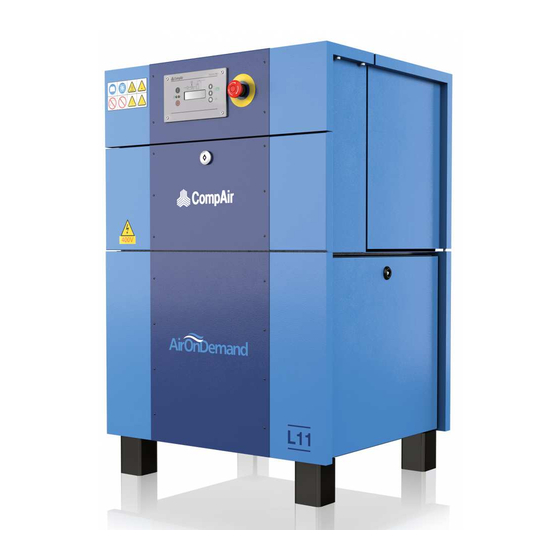
Page 20: Design And Functioning
4. Design and functioning Desig n a n d f un cti oni ng Design of the unit 4.1.1 Design of the unit L07-L11 Fig. 3 a L07-L11 1 Intake filter 12 Oil cooler 23 Control keypad 2 Intake regulator... -
Page 21: Design Of The Unit L15-L22
4. Design and functioning 4.1.2 Design of the unit L15-L22 Fig. 3 b L15-L22 1 Intake filter 12 Oil cooler 23 Control keypad 2 Intake regulator 13 Safety valve 24 EMERGENCY OFF push-button 3 Electric motor 14 Pressure holding and check valve 25 Control cabinet 4 Screw compressor 15 Air cooler... -
Page 22: Schematic Diagram
4. Design and functioning Schematic diagram 4.2.1 Schematic diagram L07-L11 Residual pressure 2 bar Opening pressure 4.5 bar Opening temp. 55 °C Fig. 4 a L07-L11 1 Intake filter 11 Oil filter B1 Network pressure sensor 2 Intake regulator 12 Oil cooler B2 Final compression pressure 2.1 Actuator... -
Page 23: Schematic Diagram L15-L22
4. Design and functioning 4.2.2 Schematic diagram L15-L22 Residual pressure 1,5 bar Opening pressure 4,5 bar Opening temperature 55 °C Fig. 4 b 1 Intake filter 11 Oil filter B1 Network pressure sensor 2 Intake regulator 12 Oil cooler B2 Final compression pressure 2.1 Actuator 13 Safety valve sensor... -
Page 24: Oil Circuit
• When the system is at rest the intake regulator (- 2 - Fig. 5a) is opened. Excess pressure of approx. 2 bar/ 29 PSI (L07-L11 residual pressure) or 1.5 bar/22 PSI (L15-L22 residual • The solenoid valve (Y1 Fig. 5a) is de-energised. -
Page 25: System Control L15-L22
4. Design and functioning Automatic operation (open-close operation) Standstill of the system • • When the pressure reaches the upper switching When the system is at rest the intake regulator point set on the network pressure sensor (-7 - Fig. (- 2 - Fig. -
Page 26: Hood (Opening/Closing)
4. Design and functioning Hood (opening/closing) The compressor is provided with a detachable plastic hood that allows easy access to all parts that are subject to servicing. Opening / closing the hood (Fig. 6) • Open the lock ( - 1 - Fig. 6) •... -
Page 27: Transport And Installation
5. Transport and installation Tr ans por t an d i ns tall ati on Installation Transport A = 0.5 m B = 0.8 m Fig. 7 Fig. 8 Note Danger • Before transporting the unit, remove the doors. The weight carrying capacity of the foundation has to be taken into account when installing the Danger compressor. -
Page 28: Preparations For Commissioning
CompAir screw compressors are rated for ambient temperatures and cooling temperatures of +1°C/ 33.8°F to +45°C/113°F. In the case of temperatures other than the above limiting values, please consult your technical adviser. -
Page 29: Electrical Connection
6. Preparations for commissioning Electrical connection Recommended supply cable cross-sections and fuses Installed nominal Fuse protection Line cross section Compressor type Supply voltage motor power (slow-blow fuse) at 30°C [kW] [AgL] 50-Hz-Compressors 4G2,5 11,0 4G10 11,0 15,0 4G16 15,0 18,5 4G25 18,5 4G10... - Page 30 6. Preparations for commissioning The electrical connection and protective measures Checking the setting of the control-power have to be installed in accordance with VDE, BS or transformer local regulations. As a rule, additional instructions The control-power transformer is factory-preset to the of the relevant power supplier have also to be rated voltage.
-
Page 31: Electric Motor Fasteners For Secure Transportation
6. Preparations for commissioning Electric motor fasteners for secure Oil level check transportation Danger Fasteners used for securing the electric motor (- 1 - Fig. Only check the oil level when the screw 13) during transportation must be removed prior to compressor unit is out of operation and commissioning. -
Page 32: Sound Pressure Level
6. Preparations for commissioning Sound pressure level Sound pressure level measured in dB(A) according to PN8NTC 2.2 under full load at a distance of 1 m (tolerance: ± 3 dB(A)): 50 Hz compressors dB(A) 60 Hz compressors dB(A) Subject to technical revision. -
Page 33: Commissioning
The access panels may temporarily be opened for Important checking the direction of rotation (wear ear protectors). Although every CompAir screw compressor has been subjected to a test run at the factory and has Danger again been thoroughly inspected before shipment, damage during shipment cannot be excluded. -
Page 34: Routine Commissioning
7. Commissioning Routine commissioning Commissioning after malfunction Danger Important Make sure before commissioning that nobody is in Do not switch the screw compressor on repeatedly the danger zone of the motor/screw compressor. without having rectified the malfunction, since this may cause considerable damage to the machine. After completion of work: Verify that all safety devices have been refitted and that all tools have Re-start after an automatic shutdown due to a... -
Page 35: Control System
8. Control system Contr ol s yst em Status indicator (display / light General signals) This chapter is used to quickly commission the unit. The control system is explained in detail in the separate The control system is fitted with a three-row display. DELCOS Pro operating instructions. -
Page 36: Displaying / Changing Values
8. Control system Displaying / changing values Default settings 8.4.1 Selecting values Danger You can display values, e.g. total hours, and set the When programming in standby, the machine may control system, e.g. cut-in and cut-out times, in the sub- start up at any time. -
Page 37: Setting Time/Date (Timer)
8. Control system 8.5.3 Setting time/date (timer) Emergency off button The DELCOS Pro accumulator can bridge a loss of The emergency off button is located above the power lasting between around two to three weeks. If DELCOS Pro . It is used to immediately shut down the power is lost for longer periods, the timer's time and unit. -
Page 38: Menu Structure (Values Are Examples)
8. Control system 8.10 Menu structure (values are examples) + TOTAL RUNNING 12345h [MAINTENANCE SCHED.] LOADED HOURS 10987h + AIR FILTER IN 2000h OIL FILTER IN 2000h ... -
Page 39: Service And Maintenance
In order to facilitate this task, the scope of supply of the out when the following points are observed: screw compressor unit comprises the “Maintenance and inspection manual for CompAir compressors”, in which • Press the STOP button on the control panel and... - Page 40 V-belt set (recommendation) Maintenance items W1 European-version W7 Checking/tightening of connecting terminals in Oil change (CompAir - 4000 hours oil) the switch cabinet/ and checking of the Valid for normal industrial environments (when in “control transformer” setting doubt, check the oil change intervals by carrying...
-
Page 41: Oil Change
4 Max. oil level 5 Min. oil level • Fill in oil up to the marking “maximum oil level” 6 Oil drain R1/2" (- 4 - Fig. 17) (L07-L11 approx. 5 litres, L15-L22 approx. 6 litres) Danger • Close the oil filler cap Only change the oil when the screw compressor •... -
Page 42: Change Of Oil Filter Cartridge
9. Service and maintenance • Check oil level (see chapter 6.5) Change of oil filter cartridge • If required, top up oil. Changing intervals for oil filter cartridge The operating conditions (e.g. coolant temperatures), the operating modes and the quality of the intake air (e.g. -
Page 43: Change Of Air Intake Filter
(e.g. content of dust, content of gaseous foreign matter 9.7.1 Change of air intake filter L07-L11 such as SO , solvent vapours, etc.) have a strong influence on the service life of the filters (air filters, oil filters, fine separators). -
Page 44: Changing Of Air Intake Filter L15-L22
9. Service and maintenance 9.7.2 Changing of air intake filter L15-L22 Safety valve Fig. 22 L15-L22 Fig. 21 1 Safety valve 1 Air filter housing cover 2 Air filter housing 3 Air filter element Testing the safety valve 4 Fixing clip The valve should be tested on a separate compressed air line in accordance with local legislation. -
Page 45: Changing V-Belts/Automatic Tensioning System
9. Service and maintenance Changing the V-belt is carried out as follows: Changing V-belts/automatic • tensioning system Remove the panel (- 5 - Fig. 23) by loosening the capscrews (- 6 - fig. 34) Danger • Remove the cover cap ( - 1 - Fig. 23) from the Only perform checks and carry out work when the access panel screw compressor unit is out of operation and... -
Page 46: General Maintenance And Cleaning
3 Bottom access panel accurately in accordance with the actual operating conditions by analyzing the oil. Danger Only perform filter mat change after the Use the following oil type: compressor system has been shut down and depressurized! European version CompAir „4000“... -
Page 47: Trouble-Shooting
10. Trouble-shooting Tr ou ble -s ho oti ng Malfunction Possible cause Remedy Unit cannot be started No operating or control voltage Check fuses, main switch and supply line Malfunction not acknowledged Acknowledge fault message Pressure reservoir not depressurized Wait until depressurized Electric motor defective Check connections, winding, etc. - Page 48 10. Trouble-shooting Malfunction Possible cause Remedy Unit switches off Ambient temperature too high Ventilate compressor room Electric motor defective Check electric motor and thermistor Fan defective Check/replace fan Cross section of the electric supply Measure power requirement, lines too small if necessary, replace lines Power requirement too high Oil fine separator clogged,...
-
Page 49: Annex
11. Annex Ann ex 11.1 Technical data EUROPE version L07-L22 50 Hz Technical Data L07-L11 50Hz Maximum operating pressure Minimum operating pressure Ambient temperature °C + 1 / + 45 Flow /min 1,14 0,93 0,69 1,68 1,41 1,14 Final compression temperature above ambient temp. -
Page 50: Technical Data Europe Version L07-L22 60 Hz
11. Annex 11.2 Technical data EUROPE version L07-L22 60 Hz Technical Data L07-11 ; 60 Hz Maximum operating pressure Minimum operating pressure Ambient temperature °C + 1 / + 45 Flow /min 1,15 1,00 0,69 1,61 1,53 1,14 Final compression temperature above ambient temp. -
Page 51: Layout Plan L07-L11
11. Annex 11.3 Layout plan L07-L11 FRONT VIEW REMOVABLE HOOD Compressed air connection R3/4“ Electrical connection View “X” Air inlet Cooling-air outlet Access panel Service aperture (V-belt relief) Oil drain R1/2“ Fig. 25... -
Page 52: Layout Plan L15-L22
11. Annex 11.4 Layout plan L15-L22 FRONT VIEW REMOVABLE HOOD Compressed air connection R1“ (1“ NPT/USA) Electrical connection View “X” Air inlet Cooling-air outlet Access panel Service aperture (V-belt relief) Oil drain R1/2“ Fig. 26... - Page 56 CompAir Drucklufttechnik GmbH Argenthaler Str. 11 55469 Simmern Deutschland Tel. ++49 (0)6761 832-0 Fax ++49 (0)6761 832-409 w w w.compair.com e-mail: sales@compair.com...
Need help?
Do you have a question about the L07 and is the answer not in the manual?
Questions and answers
Неполадка исч. напряжения
For voltage issues with CompAir part number L07, follow these troubleshooting steps:
1. Check the cross section of the electric supply lines – Measure the power requirement. If the supply lines are too small, replace them with appropriately sized lines.
2. Ensure adequate electrical power supply – Make sure the voltage matches the required specification (e.g., 200V, 230V, 460V, or 575V) and that the power supply is suitable for industrial equipment.
3. Verify fuse rating and line cross section – Use the correct slow-blow fuse and AWG conductor size based on the voltage:
- 200V: 40A, AWG 6/8/8
- 230V: 35A, AWG 8/8/10
- 460V: 20A, AWG 14/14/14
- 575V: 15A, AWG 14/14/16
4. Use a fused line disconnect switch or circuit breaker – Ensure electrical power can be safely disconnected.
These steps help ensure correct voltage supply and prevent electrical damage.
This answer is automatically generated
Не работает модуль дисплей
If the display module of a CompAir L07 is not working despite voltage being applied, follow these troubleshooting steps:
1. Check for Internal Drive Errors – If the display is not visible, an internal drive error may be the cause.
2. Replace the Lubrication System – If an internal drive error is confirmed, the entire lubrication system should be replaced.
These steps should help resolve the issue with the display module.
This answer is automatically generated