Table of Contents
Advertisement
CompAir UK Ltd
OPERATOR MANUAL
For a
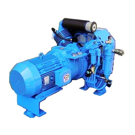
H5211
Air Cooled Air Compressor
In any correspondence please quote;
COMPAIR JOB NUMBER:-
CUSTOMER:-
CUSTOMER ORDER NUMBER:-
MACHINE NUMBER:-
PUBLICATION NUMBER:- 98407.1050
ISSUE DATE:-JAN 2009 – issue 2
CompAir UK Ltd. Reavell House
53-56 White House Road IPSWICH ENGLAND IP1 5PB
Telephone: +44 (0) 1473 242000 Fax: +44 (0) 1473 745451 Parts Fax: +44 (0) 1473 743468 Service +44 (0) 1473 242097
www.compair.com
e-mail:- sales.ipswich@compair.com
Advertisement
Table of Contents

Subscribe to Our Youtube Channel
Related Manuals for CompAir H5211


Summary of Contents for CompAir H5211
- Page 1 PUBLICATION NUMBER:- 98407.1050 ISSUE DATE:-JAN 2009 – issue 2 CompAir UK Ltd. Reavell House 53-56 White House Road IPSWICH ENGLAND IP1 5PB Telephone: +44 (0) 1473 242000 Fax: +44 (0) 1473 745451 Parts Fax: +44 (0) 1473 743468 Service +44 (0) 1473 242097 www.compair.com...
-
Page 3: Table Of Contents
CompAir UK Ltd PUBLICATION 98407/1050 Page 1 OPERATOR HANDBOOK FOR A 5211.2.IA. AIR-COOLED COMPRESSOR SAFETY ............................... 3 OWNERSHIP DATA ..........................4 FOREWORD............................5 CAUTION .............................. 6 SAFETY PROCEDURES........................6 1.4.1 GENERAL............................7 1.4.2 WARNINGS, CAUTIONS & NOTES ..................... 7 1.4.3 GENERAL SAFETY PRECAUTIONS ................... - Page 4 CompAir UK Ltd PUBLICATION 98407/1050 Page 2 UNPACKING ............................22 HANDLING............................22 MOUNTING............................22 DRIVE..............................22 CONNECTIONS, PIPEWORK AND FITTINGS .................. 22 ELECTRICAL ............................23 SITING REQUIREMENTS ........................23 TYPICAL CONTROL WIRING DIAGRAM ..................24 COMMISSIONING OR RECOMMISSIONING................... 25 LUBRICATION ............................ 25 BEFORE STARTING ..........................
-
Page 5: Safety
WARNING The use of replacement parts or lubricating oils not supplied, recommended or approved by CompAir UK Ltd Ipswich, or the failure to maintain this equipment in accordance with the maintenance instructions, may invalidate the WARRANTY, cause equipment failure, create unsafe or hazardous conditions or result in damage to the equipment. -
Page 6: Ownership Data
Parts Fax: +44 (0) 1473 743468 Contact Names: Service: +44 (0) 1473 242097 For any comments or queries about the contents of this manual, please write to CompAir UK Ltd. at the above address, marked for the attention of Mr. Owen Dale, Technical Author. -
Page 7: Foreword
1.2 FOREWORD SPECIAL ATTENTION The STANDARD BUILD of all CompAir UK Ltd (Ipswich Operations) products are not intended for use in either Explosive or Potentially Explosive Atmospheres as defined in Directive 95/9/EC. An Explosive atmosphere is a mixture with air, under atmospheric conditions, of flammable gases, vapours, hazes or dusts in which, after ignition has occurred, combination propagates to the entire unburned mixture and may cause a hazard. -
Page 8: Caution
- refer to the “Maintenance Section”. Conditions of CompAir UK Ltd Ipswich warranty are stated in our Conditions of Sale. Details of warranty for a particular unit may be obtained from the local CompAir Company or authorised Distributor. -
Page 9: General
CompAir UK Ltd then they must ensure that the unit will not be damaged or made unsafe and that there is no risk to persons or property. -
Page 10: General Safety Precautions
Never remove or tamper with safety devices, guards or insulation fitted. In order to limit the risk of Legionnaires Disease, CompAir UK LTD advise caution with the use of cooling towers for water cooling the compressor. Closed circuit or direct mains cooling is preferred. -
Page 11: Maintenance & Repair Precautions
CompAir UK Ltd PUBLICATION 98407/1050 Page 9 • Do not open starter compartment to touch electrical components while voltage is applied unless it is necessary for measurement, test or adjustment. Such work should always be carried out by a qualified. -
Page 12: Precautions In The Event Of Fire
Remove the securing screws and take out valve cover. • Use only lubricating oils and greases approved by CompAir UK LTD to avoid potential hazards especially the risk of explosion or fire and the possibility of decomposition or generation of hazardous gases. -
Page 13: Amendments
CompAir UK Ltd PUBLICATION 98407/1050 Page 11 2 AMENDMENTS ISSUE REASON DATE PAGE JUNE 2001 NEW SERVICE PLAN JAN 2009... - Page 14 CompAir UK Ltd PUBLICATION 98407/1050 Page 12...
-
Page 15: Logsheet
CompAir UK Ltd PUBLICATION 98407/1050 Page 13 3 LOGSHEET... - Page 16 CompAir UK Ltd PUBLICATION 98407/1050 Page 14...
-
Page 17: General Description And Operation
CompAir UK Ltd PUBLICATION 98407/1050 Page 15 4 GENERAL DESCRIPTION AND OPERATION Suction Filter 1st Stage Silencer Safety Valve Final Stage 2nd Stage Safety Valve Pressure Gau Fusible 1st Stage Pressure Gauge Final Delivery Connection Non-Return Valve 1st Separator &... -
Page 18: Lubrication
Recommendations are the result of extensive research by CompAir UK and all responsibility for the use of an oil, other than that recommended, is placed on the purchaser and the company supplying his oil. -
Page 19: Leading Particulars
CompAir UK Ltd PUBLICATION 98407/1050 Page 17 5 LEADING PARTICULARS 5.1 UNIT DESIGNATION Reciprocating, air cooled, medium pressure compressor, for either direct or belt drive applications ................5211 5.2 TECHNICAL DATA Type ....................Two cylinder, two stage Cooling ......................Fan activated air Direction of rotation viewed from drive end ............ -
Page 20: Temperatures
(For lower than normally recommended temperature duties consult CompAir UK.) Oil capacity of crankcase.................... litres 1.4 Recommended silicone grease (for assembly) ........Dow Corning MS33 * ( Running in & low pressure conditions only. Consult CompAir UK) 5.11 TORQUE SETTINGS ALL FIGURES ± 5%... -
Page 21: Running Clearances
CompAir UK Ltd PUBLICATION 98407/1050 Page 19 5.12 RUNNING CLEARANCES DESCRIPTION STAG AS FITTED MAX PERMISSIBLE (mm) WEAR LIMITS (mm) 0.4/0.6 Piston Ring Gap Piston Rings 0.2/0.4 Piston Ring Gap Piston Rings Piston Ring/Groove Width Clearance Piston Rings 0.02/0.05 0.25 Oil Control Ring 0.03/0.07... - Page 22 CompAir UK Ltd PUBLICATION 98407/1050 Page 20...
-
Page 23: Installation
CompAir UK Ltd PUBLICATION 98407/1050 Page 21 6 INSTALLATION Lifting Stage Eyes Cylinder Assembly 1st Stage Cylinder Final Assembly Delivery Connection Direct Drive Inspection Oil Filler, Cover Level and Drain Fitting Separator Drain Connections ½"BSP. Electrical Connection Drains DIN Electrical... -
Page 24: Unpacking
CompAir UK Ltd PUBLICATION 98407/1050 Page 22 6.2 UNPACKING Unless the compressor set is delivered uncrated, certain components, e.g. anti-vibration To avoid the loss of these items they should be located and removed first. After unpacking, fit any items which were loose in the crate and are now required for installing the set. To refit anti-vibration mounts (if supplied), first read the information under HANDLING (section3.3 below), then raise the... -
Page 25: Electrical
CompAir UK Ltd PUBLICATION 98407/1050 Page 23 A non-return valve is fitted to the delivery fitting to allow two or more machines to be connected to a common main and delivery unloading to be used. Stop valves must be fitted in pipelines to isolate compressor and control equipment. Unloader and control piping must be as short as possible. -
Page 26: Typical Control Wiring Diagram
CompAir UK Ltd PUBLICATION 98407/1050 Page 24 6.9 TYPICAL CONTROL WIRING DIAGRAM RELAY TIMER SOLENOID VALVE HIGH TEMPERATURE CUT OUT SWITCH LOPS LOW OIL PRESSURE SWITCH MAIN PRESSURE SWITCH OPERATION START ON LOW PRESSURE SIGNAL FROM MPS. ON REACHING HIGH PRESSURE COMPRESSOR STOPS, UNLOADS AND DRAINS. -
Page 27: Commissioning Or Recommissioning
CompAir UK Ltd PUBLICATION 98407/1050 Page 25 7 COMMISSIONING OR RECOMMISSIONING W A R N I N G :- BEFORE OPERATING THIS EQUIPMENT USERS SHOULD BE MADE AWARE OF AND ENSURE COMPLIANCE WITH THE HEALTH AND SAFETY REGULATIONS APPROPRIATE TO THIS CLASS OF WORK. -
Page 28: Maintenance
CompAir UK Ltd PUBLICATION 98407/1050 Page 26 Restart the compressor and check and adjust the pressure switch setting, if necessary. After 30 minutes operation, check cylinder cover. Intake pipe to cylinder cover should be warm and outlet pipes hot. This indicates valves are functioning correctly. -
Page 29: Operation And Routine Maintenance
CompAir UK Ltd PUBLICATION 98407/1050 Page 27 8 OPERATION AND ROUTINE MAINTENANCE 8.1 OPERATION AND GENERAL MAINTENANCE Commissioning procedure should be used:- (a) For first commissioning run. (b) Following overhaul. (c) After standing idle for a long period. Crankcase oil needs to be changed after major overhaul. -
Page 30: Standing Idle
CompAir UK Ltd PUBLICATION 98407/1050 Page 28 8.5 STANDING IDLE After one week standing idle, turn the machine over by hand before starting to ensure it turns freely. If machine is to stand idle for more than five weeks (or shorter period if ambient conditions are unfavourable) it is advisable to carry out the following recommended inhibition procedure:- Fill crankcase with Shell Ensis 20 to the correct level indicated by the crankcase sight glass. -
Page 31: Maintenance Schedule
CompAir UK Ltd PUBLICATION 98407/1050 Page 29 9 MAINTENANCE SCHEDULE W A R N I N G :- BEFORE PROCEEDING WITH MAINTENANCE ON THE COMPRESSOR IT MUST BE STOPPED AND ISOLATED ELECTRICALLY AND MECHANICALLY AND VISIBLE WARNING NOTICES DISPLAYED. IN ADDITION ALL INTERNAL PRESSURE MUST BE RELEASED AND THE COMPRESSOR ISOLATED FROM THE RECEIVER. - Page 32 CompAir UK Ltd PUBLICATION 98407/1050 Page 30...
-
Page 33: Recommended Maintenance Schedule
CompAir UK Ltd PUBLICATION 98407/1050 Page 31 9.4 RECOMMENDED MAINTENANCE SCHEDULE Service Kit Number SERVICE SCHEDULE 5211 MK2 AIR Run Hours Task Description Parts Provided Reavellite S lubricant 1 Change crankcase oil 1.35 litre Litre Suction Filter Element Element Joint kit Joint kit Remove 1st stage valve &... - Page 34 CompAir UK Ltd PUBLICATION 98407/1050 Page 32 Service Kit Number SERVICE SCHEDULE 5211 MK2 AIR Run Hours Task Description Parts Provided Check tightness of all fasteners(PARTICULARLY COOLER CLAMP FASTENERS) Inspect 1st stage cylinder assy cylinder assy. Inspect 2nd stage cylinder assy...
-
Page 35: Removal And Replacement Of Valves
CompAir UK Ltd PUBLICATION 98407/1050 Page 33 REMOVAL AND REPLACEMENT OF VALVES 10.1 GENERAL Valves may have a thin carbon layer and should be slightly moist with oil. Valve maintenance is a simple procedure provided the following guidelines are observed. -
Page 36: 2Nd Stage Valve
CompAir UK Ltd PUBLICATION 98407/1050 Page 34 10.4 2ND STAGE VALVE 10.4.1 REMOVAL Undo pressure gauge pipe detach and remove pressure gauge. Remove main fan guard only, as described above in 1st stage valve removal. Detach second stage suction pipe and delivery pipe coupling nuts. Remove pressure gauge panel retaining screw from cylinder cover. -
Page 37: Fault Guide
CompAir UK Ltd PUBLICATION 98407/1050 Page 35 11 FAULT GUIDE W A R N I N G :- BEFORE PROCEEDING WITH MAINTENANCE ON THE COMPRESSOR IT MUST BE STOPPED AND ISOLATED ELECTRICALLY AND MECHANICALLY AND VISIBLE WARNING NOTICES DISPLAYED. IN ADDITION ALL INTERNAL PRESSURE MUST BE RELEASED AND THE UNIT ISOLATED FROM THE RECEIVER. - Page 38 CompAir UK Ltd PUBLICATION 98407/1050 Page 36...
- Page 39 CompAir UK Ltd PUBLICATION 98407/1050 Page 37 Fault Probable Cause Recommendation(s) Faulty suction or delivery Service valve(s) as necessary. EXCESSIVE valve(s). NOTE: A faulty suction valve gives excess PRESSURE pressure in previous stage. Pressure gauge inaccurate. Check gauge against instrument of known accuracy.
- Page 40 CompAir UK Ltd PUBLICATION 98407/1050 Page 38 How to order spares IN ORDER TO AVOID UNNECESSARY DELAY, PLEASE QUOTE:- 1. Complete invoicing and shipping address 2. Machine Model Reference No. 3. Machine No. 4. Item Reference 5. Part No. 6. Description...
-
Page 41: Parts List
CompAir UK Ltd PUBLICATION 98407/1050 Page 39 12 PARTS LIST CONTENTS LIST CRANKCASE..............001 - 005 RUNNING GEAR ..............006 - 010 1st & 2nd STAGE CYLINDERS......... 011 - 019 COOLING ASSEMBLY............020 - 024 COOLING ASSEMBLY Cont..........025 - 035 MAINTENANCE KITS............ - Page 42 CompAir UK Ltd PUBLICATION 98407/1050 Page 40 TORQUE WRENCH SETTINGS 5.10,5.11,5.13 27 Nm 20 lbf/ft 5.10 03.6 95 Nm 70 lbf/ft END FLOAT 0.15/0.35mm 5.17 5.16 5.15 5.5/5.7 5.13 5.12 5.11 .8/.9 .6 .2 .1 .5 .3 .4 5.14 5.7/5.8...
- Page 43 CompAir UK Ltd PUBLICATION 98407/1050 Page 41 CRANKCASE PARTS ITEM DESCRIPTION PART No BEARING HOUSING D/E Parts:- LE13506.100* Joint E1320 Bearing Housing E13506# Retaining Plate E13527 Screw Csk 95050.348 Bearing Main D/E 96008.18 Oil Seal 98505.1021 BEARING HOUSING O/E Parts:- E61120.100*...
- Page 44 CompAir UK Ltd PUBLICATION 98407/1050 Page 42 TORQUE WRENCH SETTINGS 08.5 55 Nm 40 lbf/ft 10.10 95 Nm 70 lbf/ft T.D.C. CLEARANCES 1 stage 0.25/1.15mm 2 stage 8.25/9.05MM .3a .3b 10.5 10.9 10.2 10.1 10.3 10.7 10.6 10.11 Letf hand...
- Page 45 CompAir UK Ltd PUBLICATION 98407/1050 Page 43 RUNNING GEAR PARTS ITEM DESCRIPTION PART No 5211.2 PISTON 2nd STAGE Parts:- D101149.50* Piston D101149# Gudgeon Pin C202864 Circlip 95650.21 Piston Ring E2133# Piston Ring 98477.1123# Piston Ring Set 98477.1131* PISTON 1st STAGE Parts:- D101549.100*...
- Page 46 CompAir UK Ltd PUBLICATION 98407/1050 Page 44 TORQUE WRENCH SETTINGS 14.3,15.9 27 Nm 20 lbf/ft 13.4 95 Nm 70 lbf/ft 15.13 15.10 15.13 15.12 15.7 15.9 15.6 15.5 15.1 15.14 15.4 15.15 11 .1 15.11 15.2 15.8 .3 12 11-19...
- Page 47 CompAir UK Ltd PUBLICATION 98407/1050 Page 45 1st & 2nd STAGE CYLINDER PARTS ITEM DESCRIPTION PART No No OFF VALVE ASSY 1st STAGE Parts:- C202860* 'O' Rng 95602.85 'O' Ring 95602.97 Valve - Concentric 98650.1831# VALVE ASSY 2nd STAGE Parts:-...
- Page 48 CompAir UK Ltd PUBLICATION 98407/1050 Page 46 TORQUE WRENCH SETTINGS 20.26,/27,/28,/33,/34,/35,/38./39 11 Nm 8 lbf/ft 20.34 20.29,/30,/31,/32,/37,/40 27 Nm 20 lbf/ft 20.35 20.39 20.46 20.32 2 off pipe clips fitted where marked (¥) 20.17 20.42 20.10 20.9 20.28 20.3 20.33 20.2...
- Page 49 CompAir UK Ltd PUBLICATION 98407/1050 Page 47 COOLING ASSEMBLIES ITEM DESCRIPTION PART No No OFF 20.1 FAN GUARD & DUCT A30099 20.2 BRACKET COOLER CU41239 20.3 CLIP COOLER C200926 20.4 FERRULE C202619 20.5 BRACKET COOLER C202819 20.6 SUPPORT BAR - TOP C202820 20.7...
- Page 50 CompAir UK Ltd PUBLICATION 98407/1050 Page 48 TORQUE WRENCH SETTINGS 35.6,35.8 11 Nm 8 lbf/ft 30.5,30.6,35.7 27 Nm 20 lbf/ft 30.1 30.7 30.8 30.3 30.5 25.2 25.1 30.4.1 30.2 25.3 See page 20-24 20.51 for details of 30.6 pressure gauge 25.4...
- Page 51 CompAir UK Ltd PUBLICATION 98407/1050 Page 49 COOLING ASSEMBLIES Cont. ITEM DESCRIPTION PART No No OFF 20.18 FAN GUARD INNER E61130 20.19 PLUG 3/8" BSP PS1068.3 20.20 PLUG 1/8" BSPT PS1454.1 20.21 WASHER TAPER M8 PS1742.1 20.22 RED CAP PS2023.2 20.23...
- Page 52 CompAir UK Ltd PUBLICATION 98407/1050 Page 50 TORQUE WRENCH SETTINGS 35.6,35.8 11 Nm 8 lbf/ft 30.5,30.6,35.7 27 Nm 20 lbf/ft 30.1 30.7 30.8 30.3 30.5 25.2 25.1 30.4.1 30.2 25.3 See page 20-24 20.51 for details of 30.6 pressure gauge 25.4...
- Page 53 CompAir UK Ltd PUBLICATION 98407/1050 Page 51 COOLING ASSEMBLIES Cont. ITEM DESCRIPTION PART No No OFF 30.4 SEPARATOR 2nd STAGE ASSY parts:- D101623 30.4 SEPARATOR 2nd STAGE ASSY parts:- D101192 Nut Collar C200752 Body Separator C201603 Ferrule C202619 Shroud C202869...
- Page 54 CompAir UK Ltd PUBLICATION 98407/1050 Page 52 MAINTENANCE KITS ITEM DESCRIPTION PART No No OFF MAINTENANCE JOINT KIT 98504.1292* 12.1 Joint 2nd Stage Valve to Cylinder C202284 12.2 Joint 2nd Stage Valve to Cover C202285 01.1/02.1 Joint D/E & O/E Bearing Hsg to Crankcase E1320 11.1...
-
Page 55: Ancillary Equipment
CompAir UK Ltd PUBLICATION 98407/1050 Page 53 13 ANCILLARY EQUIPMENT 13.1 ELECTRIC MOTOR – APP034 ELECTRIC MOTOR MAINTENANCE WARNING : Isolate power supply to motor before commencing any routine cleaning or maintenance work. Routine Cleaning : Remove the fan cover and ensure that all holes are completely open. Clear any dirt and fluff from behind the fan and along the ribs of the frame. -
Page 56: High Air Pressure Switch - App086
CompAir UK Ltd PUBLICATION 98407/1050 Page 54 13.2 HIGH AIR PRESSURE SWITCH – APP086 HIGH AIR/GAS PRESSURE SWITCHES PART NO: 98524/1025, 1049, 1094, 1095, 1096, 1102, 1103, 1104, 1107, 1128, 1135, 1136, 1137, 1210 & 1212 OPERATION - MANUAL START/AUTO STOP Located as close as possible to the delivery, inlet air/gas line, the pressure switch stops the compressor when the air/gas pressure rises or falls above or below the pre-set pressure setting. - Page 57 "Pressure Switch". Remove cover to set pressure setting, using a pressure gauge. Note:- Switches are pre-set and do not usually need adjusting. Please confirm with Engineering at CompAir UK Ltd Ipswich if switches are to be adjusted. Turn adjusting nut clockwise to lower set point.
-
Page 58: Direct Drive - App011B
CompAir UK Ltd PUBLICATION 98407/1050 Page 56 13.3 DIRECT DRIVE – APP011B DIRECT DRIVE: Ensure compressor and drive motor is correctly aligned as the flexible couplings are for vibration duties only and not as non-alignment couplings. Note direct coupled sets with bell type housing (see below) are self aligning. -
Page 59: Solenoid Valve - App171
CompAir UK Ltd PUBLICATION 98407/1050 Page 57 13.4 SOLENOID VALVE – APP171 2 WAY NORMALLY OPEN SOLENOID VALVE OPERATION 2 way normally open, energise to close, continuous duty. On starting the solenoid valve is open. When energised the valves will close thus allowing pressure to build up in the system to the desired pressure. - Page 60 CompAir UK Ltd PUBLICATION 98407/1050 Page 58 INSTALLATION Electrical connection Amps pin to DIN 46242 Connector To DIN 43650 Protection IP65 Cable thread size Coil Class 'H' 180°C insulation Coil duty Continuous Voltage tolerance from normal - 10% to +10% Working fluid Air, water, gas, fuel oil &...
- Page 62 WARNING The use of replacement parts or lubricating oils not supplied, recommended or approved by CompAir UK Ltd. Ipswich, may lead to failure in service which would not be covered by the warranty. Any unauthorised modifications or failures to maintain this equipment is accordance with the manufacturers maintenance instructions may make it unsafe.
Need help?
Do you have a question about the H5211 and is the answer not in the manual?
Questions and answers