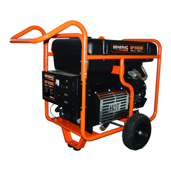
Generac Power Systems GP15000E Owner's Manual
Hide thumbs
Also See for GP15000E:
- Quick setup manual (12 pages) ,
- Specification (2 pages) ,
- User manual
Table of Contents
Advertisement
Available languages
Available languages
GP Series Portable Generator
SAVE THIS MANUAL FOR FUTURE REFERENCE
SAVE THIS MANUAL FOR FUTURE REFERENCE
Owner's Manual
MODEL:________________________
SERIAL:________________________
DATE PURCHASED:______________
This product is not intended to be used in a
critical life support application. Failure to adhere
to this warning could result in
death or serious injury.
Register your Generac product at:
WWW.GENERAC.COM
1-888-GENERAC
(1-888-436-3722)
WARNING
000915
(000209)
Advertisement
Chapters
Table of Contents
Troubleshooting

Related Manuals for Generac Power Systems GP15000E


Summary of Contents for Generac Power Systems GP15000E
- Page 1 GP Series Portable Generator Owner’s Manual 000915 MODEL:________________________ SERIAL:________________________ DATE PURCHASED:______________ WARNING This product is not intended to be used in a critical life support application. Failure to adhere to this warning could result in death or serious injury. (000209) Register your Generac product at: WWW.GENERAC.COM 1-888-GENERAC...
-
Page 2: Table Of Contents
Table of Contents Section 1 Introduction and Safety 1 Section 4 Maintenance and Introduction ........1 Troubleshooting ......14 Safety Rules ........1 Maintenance Recommendations ...14 Safety Symbols and Meanings ..1 Maintenance Schedule ....14 Exhaust and Location Hazards ..2 Preventive Maintenance ....14 Electrical Hazards ...... -
Page 3: Section 1 Introduction And Safety
Section 1 Introduction and Safety Introduction Thank you for purchasing a Generac Power DANGER Systems Inc. product. This unit has been designed to provide high-performance, effi- Indicates a hazardous situation which, if not avoided, cient operation, and years of use when main- will result in death or serious injury. -
Page 4: Exhaust And Location Hazards
• This exhaust system must be properly WARNING maintained. Do nothing that might render the exhaust system unsafe or in noncompli- Do not insert any object through the air cooling slots. ance with any local codes and/or stan- Generator can start at any time and could result in dards. -
Page 5: Electrical Hazards
Electrical Hazards WARNING DANGER Do not insert any object through the air cooling slots. Generator can start at any time and could result in Electrocution. Contact with bare wires, death, serious injury, and unit damage. terminals, and connections while generator (000142) is running will result in death or serious injury. -
Page 6: Section 2 General Information And Setup
Section 2 General Information and Setup 000919 000920 000921 Figure 2-1. Features and Controls TABLE 1. Generator Components 12 Volt DC, 10 Amp Receptacle 120 Volt AC, 20 Amp Duplex Receptacle 120 Volt AC, 20 Amp, GFCI Duplex Receptacle (NEMA 5-20R) 120 Volt AC, 30 Amp Locking Receptacle (NEMA L14-30R) 120/240 Volt AC, 30 Amp Locking... -
Page 7: Know Your Generator
Know Your Generator • Air Induction System – Intake Pipe / Manifold – Air Cleaner WARNING • Fuel System Consult Manual. Read and understand manual – Carburetor completely before using product. Failure to – Fuel Tank / Cap completely understand manual and product could result in death or serious injury. -
Page 8: Hour Meter
Hour Meter The Hour Meter tracks hours of operation for scheduled maintenance. See Figure 2-3. • The CHG OIL display will illuminate every 100 hours. The message will flash one hour before and one hour after each 100 hour interval, providing a two hour window to perform service. -
Page 9: 120/240 Vac, 50 Amp Receptacle
120/240 VAC, 50 Amp receptacle Use a NEMA 14-50 plug with this receptacle. Connect a 4-wire cord set rated for 250 Volts AC at 50 Amps to plug Figure 2-9. Use this receptacle to operate 120/240 Volt AC, 60 Hz electrical loads requiring up to 12,000 watts (12.0 kW) of power. -
Page 10: Assembly
Hardware Bag Qty. Cotter Pin (F) Plastic Spacer (G) Locking Flange Nut (H) Hex Head Bolt (J) Lock Washer (K) Flat Washer (L) Capscrew (5/16 x 1) (M) Capscrew (5/16 x 2-1/2) (N) 000925 3. Call Generac Customer Service 1-888- GENERAC (1-888-436-3722) with the unit model and serial number for any missing carton contents. -
Page 11: Fuel
Fuel DANGER Explosion and Fire. Fuel and vapors are extremely flammable and explosive. Add fuel in a well ventilated area. Keep fire and spark away. Failure to do so will result in death or serious injury. (000105) DANGER Do not overfill fuel tank. Fill to 1/2 in. of top of tank to allow for fuel expansion. -
Page 12: Section 3 Operation
Section 3 Operation Operation and Use Questions Grounding the Generator When Used as a Portable Call Generac customer service at 1-888-GEN- ERAC (1-888-436-3722) with questions or The generator is equipped with an equipment concerns about equipment operation and ground connecting the generator frame and maintenance. -
Page 13: Transporting/Tipping Of The Unit
• The rated wattage of lights can be taken *Garage Door Opener 500 to 750 from light bulbs. The rated wattage of tools, Hair Dryer 1200 appliances, and motors can be found on a data label or decal affixed to the device. Hand Drill 250 to 1100 •... -
Page 14: Automatic Idle Control
5. Close fuel valve. NOTE: Under normal conditions, close fuel valve and allow generator to run carburetor bowl out of fuel. For emergencies, switch to Stop. Automatic Idle Control This feature will improve fuel economy. When the switch is turned On, the engine will only run at its normal fast governed engine speed 000929 when electrical load is connected. - Page 15 CAUTION Do not make battery connections in reverse. Doing so will result in equipment damage. (000167) The 12 VDC receptacle may be used to recharge 12 VDC automotive batteries only. The DC charging output is not regulated. The circuit protector does not prevent over- charging a battery.
-
Page 16: Section 4 Maintenance And Troubleshooting
Section 4 Maintenance and Troubleshooting Maintenance Recommendations WARNING Regular maintenance will improve perfor- Do not insert any object through the air cooling slots. mance and extend generator life. See a quali- Generator can start at any time and could result in fied dealer for service. - Page 17 Inspect Engine Oil Level Change oil while engine is still warm from run- ning, as follows: 1. Place generator on a level surface. WARNING 2. Disconnect the spark plug wire from the Risk of burns. Allow engine to cool before spark plug and place the wire where it draining oil or coolant.
-
Page 18: Battery Replacement (If Applicable)
5. Connect negative (-) battery terminal (black wire) SECOND. 6. Slide rubber boot over connection hard- ware. Inspect Muffler and Spark Arrester NOTE: It is a violation of California Public Resource Code, Section 4442, to use or oper- ate the engine on any forest-covered, brush- 000211 covered, or grass-covered land unless the Figure 4-4. -
Page 19: Valve Clearance
Valve Clearance Prepare Fuel System for Storage IMPORTANT NOTE: If uncomfortable about Fuel stored over 30 days can go bad and doing this procedure, or the proper tools damage fuel system components. Keep fuel are not available, take generator to the fresh, use fuel stabilizer. -
Page 20: Troubleshooting
Troubleshooting PROBLEM CAUSE CORRECTION Engine is running, but 1. Circuit breaker OPEN. 1. Reset circuit breaker. AC output is not 2. Poor connection or defective 2. Check and repair. available. cord set. 3. Connect another device that is 3. Connected device is bad. in good condition. - Page 21 PROBLEM CAUSE CORRECTION No battery charge DC 1. Battery posts corroded. 1. Clean battery posts. output. 2. Bad battery cable. 2. Replace cable. 3. Defective battery. 3. Check battery condition. 4. Bad receptacle. Replace if defective. 4. Contact Authorized Service Dealer.
-
Page 22: Notes
Notes Owner’s Manual for Portable Generator... - Page 24 Part No. 0H0676A Rev. A 08/06/15 Generac Power Systems, Inc. Printed in USA S45 W29290 Hwy. 59 ©2015 Generac Power Systems, Inc. All rights Waukesha, WI 53189 reserved 1-888-GENERAC (1-888-436-3722) Specifications are subject to change without notice. generac.com No reproduction allowed in any form without prior...
- Page 25 Generador portátil Serie GP Manual del propietario 000915 MODELO: ________________________ SERIE: __________________________ FECHA DE COMPRA: ______________ ADVERTENCIA Este producto no está destinado al uso en aplicaciones críticas de soporte a la vida humana. No adherir a estas instrucciones puede causar la muerte o lesiones graves.
- Page 26 Índice Sección 1 Introducción Conozca los límites y seguridad ........1 del generador ........11 Introducción ........1 Transporte e inclinación Reglas de seguridad ....... 1 de la unidad ........11 Símbolos de seguridad y sus Puesta en marcha de motores con significados ........
-
Page 27: Sección 1 Introducción Y Seguridad
Obsérvelos cuidadosamente. Sus Muchas gracias por haber comprado un producto definiciones son las siguientes: de Generac Power Systems Inc. Esta unidad ha sido diseñada para proporcionar alto rendimiento, funcionamiento eficiente, y años de uso cuando PELIGRO se mantiene apropiadamente. -
Page 28: Peligros Relacionados Con El Escape Y La Ubicación
seguro del generador. El generador DEBE ADVERTENCIA funcionar en exteriores. • Este sistema de escape debe contar con el No inserte ningún objeto a través de las ranuras de aire de enfriamiento. El generador puede arrancar en cualquier mantenimiento apropiado. No haga nada momento y puede producir la muerte, lesiones graves y que pueda volver inseguro al sistema de daños a la unidad. -
Page 29: Peligros Eléctricos
Peligros eléctricos ADVERTENCIA No inserte ningún objeto a través de las ranuras de aire de PELIGRO enfriamiento. El generador puede arrancar en cualquier momento y puede producir la muerte, lesiones graves y Electrocución. El contacto con cables, terminales, y daños a la unidad. conexiones desnudas mientras el generador está... -
Page 30: Sección 2 Información General Y Configuración
Sección 2 Información general y configuración 000919 00092 000921 Figura 2-1. Características y controles TABLA 1. Componentes del generador Tomacorriente de 12 VCC, 10 A Tomacorriente doble de 120 VCA, 20 A Tomacorriente doble GFCI de 120 VCA, 20 A (NEMA 5-20R) Tomacorriente con bloqueo de 120 VCA, 30 A (NEMA L14-30R) Tomacorriente con bloqueo de... -
Page 31: Conozca Su Generador
Conozca su generador • Sistema de inducción de aire – Tubo/colector de admisión – Depurador de aire ADVERTENCIA • Sistema de combustible Consulte el manual. Lea y comprenda completamente – Carburador el manual antes de usar el producto. No comprender –... -
Page 32: Horómetro
Horómetro El horómetro lleva un registro de las horas de funcionamiento para mantenimiento programado. Vea la Figura 2-3. • La pantalla CHG OIL (cambiar aceite) se iluminará cada 100 horas. El mensaje destellará una hora antes y una hora después de cada intervalo de 100 horas, proporcionando una ventana de dos horas para efectuar el servicio. -
Page 33: Tomacorriente De 120/240 Vca, 50 A
Tomacorriente de 120/240 VCA, 30 A (6.5 kW), o un interruptor basculante de 2 polos de 30 A, o dos disyuntores de botón de 50 A pulsar para reconectar de 30 A (6.5/7.5 kW). Use un enchufe macho NEMA 14-50 con este tomacorriente. -
Page 34: Armado
Instale una arandela plana (L) y tuerca de Bolsa de tornillería Cant. seguridad embridada (H). Pasador hendido (F) Espaciador plástico (G) Tuerca embridada (H) Perno de cabeza hexagonal (J) Arandela de seguridad (K) Arandela plana (L) Perno (5/16 x 1) (M) Perno (5/16 x 2-1/2) (N) 3. -
Page 35: Combustible
Combustible PELIGRO Explosión e incendio. El combustible y los vapores son extremadamente inflamables y explosivos. Añada combustible en una zona bien ventilada. Mantenga alejados el fuego y las chispas. No hacerlo puede ocasionará la (000105) muerte o lesiones graves. PELIGRO No llene en exceso el tanque de combustible. -
Page 36: Sección 3 Operación
Sección 3 Operación Preguntas sobre PRECAUCIÓN funcionamiento y uso Daños a los equipos y la propiedad. Desconecte las cargas Llame al Servicio al cliente de Generac al eléctricas antes de poner en marcha o parar la unidad. No 1-888-GENERAC (1-888-436-3722) con las hacer esto puede provocar daños al equipo y la propiedad. -
Page 37: Conozca Los Límites Del Generador
Conozca los límites del Rizador de pelo generador *Deshumidificador Sobrecargar un generador puede ocasionar Lijadora de disco (9 in) 1200 daños al generador y a los dispositivos eléctricos conectados. Observe lo siguiente Bordeadora para evitar sobrecargas: Manta eléctrica • Sume la potencia en vatios total de todos los dispositivos eléctricos a ser conectados Pistola de clavar eléctrica 1200... -
Page 38: Puesta En Marcha De Motores Con Arranque Eléctrico
Puesta en marcha de motores NOTA IMPORTANTE: No sobrecargue el generador. Tampoco sobrecargue con arranque eléctrico tomacorrientes individuales del tablero. Estas salidas están protegidas contra PRECAUCIÓN sobrecargas con disyuntores tipo pulsar para reconectar. Si se excede el amperaje Daños a los equipos y la propiedad. Desconecte las cargas eléctricas antes de poner en marcha o parar la unidad. -
Page 39: Sistema De Parada Por Nivel De Aceite Bajo
Sistema de parada por nivel de aceite bajo El motor tiene un sensor de nivel de aceite bajo que para el motor automáticamente cuando el nivel cae por debajo de un nivel especificado. El motor no funcionará hasta que el aceite se haya llenado al nivel apropiado. -
Page 40: Sección 4 Mantenimiento Y Resolución De Problemas
Sección 4 Mantenimiento y Resolución de problemas Recomendaciones de mantenimiento ADVERTENCIA El mantenimiento regular mejorará el rendimiento No inserte ningún objeto a través de las ranuras de aire de y prolongará la vida útil del generador. Vea a un enfriamiento. El generador puede arrancar en cualquier concesionario cualificado para servicio. - Page 41 Inspección del nivel de aceite de Cambio de aceite de motor motor ADVERTENCIA Arranque accidental. Desconecte los cables de las bujías al ADVERTENCIA trabajar en la unidad. No hacerlo puede ocasionar la muerte Riesgo de quemaduras. Espere a que el motor se o lesiones graves.
-
Page 42: Sustitución De La Batería (Si Corresponde)
Vea la Figura 4-5. 1. Desconecte en PRIMER LUGAR el terminal negativo (-) de la batería (cable negro). 2. Desconecte en SEGUNDO LUGAR el terminal positivo (+) de la batería (cable rojo). 000933 Figura 4-3. Armado del filtro de aire 00022 Figura 4-5. -
Page 43: Juego De Válvulas
2. Retire el tamiz (C) y sustitúyalo si está • NO almacene combustible de una estación a desgarrado, perforado o dañado de otra excepto esté tratado alguna otra forma. Si el tamiz no está apropiadamente. dañado, límpielo con solvente comercial. •... -
Page 44: Resolución De Problemas
Resolución de problemas PROBLEMA CAUSA CORRECCIÓN El motor está 1. Disyuntor ABIERTO. 1. Vuelva a conectar el disyuntor. funcionando, pero no hay 2. Conexión deficiente o juego de 2. Compruebe y repare. salida de CA disponible. cordones de conexión 3. Conecte otro dispositivo que se defectuoso. - Page 45 PROBLEMA CAUSA CORRECCIÓN El motor se para durante 1. Sin combustible. 1. Llene el tanque de combustible. el funcionamiento. 2. Nivel de aceite bajo. 2. Llene el cárter hasta el nivel 3. Fallo en el motor. correcto. 3. Comuníquese con un concesionario de servicio autorizado.
-
Page 46: Notas
Notas Manual del propietario para generador portátil... - Page 48 Pieza núm. 0H0676A Rev. A 06/08/15 Generac Power Systems, Inc. Impreso en EE. UU. S45 W29290 Hwy. 59 ©2015 Generac Power Systems, Inc. Todos los Waukesha, WI 53189, EE. UU. derechos reservados 1-888-GENERAC (1-888-436-3722) Las especificaciones están sujetas a cambios sin aviso.
Need help?
Do you have a question about the GP15000E and is the answer not in the manual?
Questions and answers
Which replacement battery do I need for a GP15000E? What is the procedure to change it? Thanks
The specific replacement battery type for the Generac GP15000E is not mentioned in the provided information. However, the procedure to change the battery is as follows:
1. Disconnect the negative (–) terminal (black cable) first.
2. Disconnect the positive (+) terminal (red cable) second.
3. Remove the old battery and install the new one.
4. Secure the battery using the retaining bracket.
5. Connect the positive (+) terminal (red cable) first and slide the rubber boot over the connection.
6. Connect the negative (–) terminal (black cable) second.
This answer is automatically generated