
Related Manuals for Interton ELIPSE EL90-VI


Summary of Contents for Interton ELIPSE EL90-VI
- Page 1 Technical Manual INTERTON Elipse Digital SPBTE Global Technical Operations gto.gnresound.com Lautrupbjerg 7 • DK-2750 Ballerup • Denmark E-Mail: Service@gnresound.dk...
-
Page 2: Table Of Contents
Doc 0194590 rev. C Table of Contents Subject Page Description ..................... 3 Part List ......................4 Part List - HSG Parts..................5 CROS/BICROS System ................. 6 HI Dissembly ....................7 Amplifier ......................8 Replacement of Microphone & Receiver............9 Replacement of VC & TC ................10 Test........................11 Page 2 of 11 Not subject to issue control when printed... -
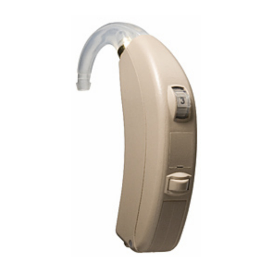
Page 3: Description
Description Doc 0194590 rev. C Model Data Sheet ELIPSE EL90-VI 17141700 Available in Beige, Brown & Grey Beige Brown Grey Page 3 of 11 Not subject to issue control when printed... -
Page 4: Part List
Part List Doc 0194590 rev. C Item Part No Item Part No MIC. SUSPENSION 15297000 HI-PRO PROG. CABLE CS44, R 9022 907 69019 MICROPHONE 33M 15240900 HI-PRO PROG. CABLE CS44, L 9022 907 69029 MICROPHONE,COMPL 15988900 TEST RING 15472600 WIRE,ESW,AMBER,7X32U,14MM 15129714 TEST FIXTURE 16611100... -
Page 5: Part List - Hsg Parts
Part List - HSG Parts Doc 0194590 rev. C HSG PARTS For HI For HI For HI HSG Parts TRANSP BEIGE BROWN GREY (optional) AU COVER,PTD 16429100 16429101 16429105 16429103 AU COVER,PTD - BLUE** 16429104 16429104 16429104 AU COVER,PTD - RED** 16429106 16429106 16429106... -
Page 6: Cros/Bicros System
CROS/BICROS System Doc 0194590 rev. C Description Part No AUDIO-BOOT (for HI) 16987200 AUDIOBOOT,BICROS (for BICROS unit) 16987500 BICROS UNIT 16987600 CROS CABLE 20 CM 7000-409 CROS CABLE 22 CM 7000-439 CROS CABLE 24 CM 7000-469 CROS CABLE 26 CM 7000-459 CROS CABLE 28 CM 7000-479... -
Page 7: Hi Dissembly
HI Disassembly Doc 0194590 rev. C Two plastic bolts holds on to the batt. door. Use a Plastic bolts Gently pull the two housing parts Gently pull out the amplifier tweezer to separate them and pull them out. It is from each other now possible to remove the door Remove rec and mic from housing... -
Page 8: Amplifier
Amplifier Doc 0194590 rev. C Page 8 of 11 Not subject to issue control when printed... -
Page 9: Replacement Of Microphone & Receiver
Replacement of Receiver & Microphone Doc 0194590 rev. C Add rubber glue to fix the wires Connect wires and mount mic into suspension Route wires and make sure to place correctly in HSG The rec is delivered as rec Place Rec in front HSG. Solder Rec wires to amplifier and route complete in box as shown them well when adding HSG parts Note: Apply coating SL1367 material on solder pads after soldering... -
Page 10: Replacement Of Vc & Tc
Replacement of Telecoil & VC Doc 0194590 rev. C VC cover Place the VC into the VC cover Add the VC plate Mount VC to amplifier. Screw VC nut and solder the two VC terminals Add glue in the grove for TC. Place TC into the grove. Connect TC wires to PCB and route them as shown Note: Apply coating SL1367 material on solder pads after soldering Page 10 of 11... -
Page 11: Test
Test & Test Equipment Doc 0194590 rev. C CS44 Prog cable Test fixture Test frame p/n 16902800 Test ring p/n 15472600 (Left blue is shown) p/n 16611100 9022 907 69019 (R) 9022 907 69029 (L) 2cc coupler p/n 30-4838800 2cc coupler BTE insert p/n 40B4609601 to be ordered with GTO Dept/HQ Ballerup DK Test ring attached the When testing the HI the test ring is needed to stabilize the HI.
Need help?
Do you have a question about the ELIPSE EL90-VI and is the answer not in the manual?
Questions and answers