Alicat Scientific MC-Series Installation & Maintenance Instructions Manual
Laminar mass flow controller
Hide thumbs
Also See for MC-Series:
- Operating manual (83 pages) ,
- Operating manual (66 pages) ,
- Operating manual (98 pages)

Related Manuals for Alicat Scientific MC-Series


Summary of Contents for Alicat Scientific MC-Series
- Page 1 Installation & Maintenance Instructions ALICAT SCIENTIFIC MC-Series Laminar Mass Flow Controller Supplied by .com Call us on +44 (0)118 916 9420 | Email info@247able.com...
- Page 2 Operating Manual WHISPER MC-Series MCS-Series MCV-Series MCR-Series Precision Gas Mass Flow Controllers The Fastest Flow Controller Company in the World!
- Page 3 FULL TECHNICAL SUPPORT | LIFETIME WARRANTY RECALIBRATION Your Alicat instrument is a precision device and Alicat strongly recommends that you send it to us on a yearly basis for recalibration. A yearly recalibration does a few things: ► It insures that your unit is functioning according to specification. ►...
- Page 4 Please take the time to read the information contained in this manual. This will help to ensure that you get the best possible service from your instrument. This manual covers the following Alicat Scientific instruments: MC-Series Mass Gas Flow Controllers...
-
Page 5: Table Of Contents
TABLE OF CONTENTS Page GETTING STARTED MOUNTING PLUMBING POWER AND SIGNAL CONNECTIONS INPUT SIGNALS Analog Input Signal RS-232 / RS-485 Digital Input Signal OUTPUT SIGNALS RS-232 / RS-485 Digital Output Signal Standard Voltage (0-5 Vdc) Output Signal Optional 0-10 Vdc Output Signal Optional Current (4-20 mA) Output Signal Optional 2nd Analog Output Signal Information for Alicat TFT (Color Display) Instruments... - Page 6 TABLE OF CONTENTS Page MCV Controller Operating Notes MCD Controller Operating Notes RS-232 or RS-485 Output and Input Configuring HyperTerminal® Streaming Mode Changing from Streaming to Polling Mode Sending a Set-Point via RS-232 or RS-485 To adjust the P & D terms via RS-232 or RS-485 Gas Select Creating and Deleting Gas Mixtures using RS-232 or RS-485 Collecting Data...
-
Page 7: Getting Started
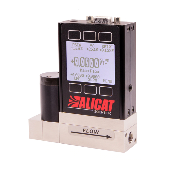
Large Valve Mass Flow Controller shown with a downstream valve configuration and connection port fittings MOUNTING MC-Series Gas Flow Controllers have holes on the bottom for mounting to flat panels. See pages 61- 82. Small valve controllers (MC-Series) can usually be mounted in any position. -
Page 8: Plumbing
Make sure that the gas will flow in the direction indicated by the flow arrow. Standard MC-Series Gas Flow Controllers have female inlet and outlet port connections. Welded VCR and other specialty fittings may have male ports. -
Page 9: Power And Signal Connections
POWER AND SIGNAL CONNECTIONS Power can be supplied to your controller through either the power jack (power jack not available on CSA/ATEX approved devices) or the 8 pin Mini-DIN connector. An AC to DC adapter which converts line AC power to DC voltage and current as specified below is required to use the power jack. -
Page 10: Input Signals
INPUT SIGNALS Analog Input Signal Apply analog input to Pin 4 as shown on page 8. For 6 Pin Locking Industrial Connector, DB9 and DB15 pin-outs see pages 85 to 98. For PROFIBUS pin-outs see page 82. Standard 0-5 Vdc is the standard analog input signal. Apply the 0-5 Vdc input signal to pin 4, with common ground on pin 8. -
Page 11: Rs-232 / Rs-485 Digital Input Signal
RS-232 / RS-485 Digital Input Signal To use the RS-232 or RS-485 input signal, connect the RS-232 / RS-485 Output Signal (Pin 5), the RS-232 / RS-485 Input Signal (Pin 3), and Ground (Pin 8) to your computer serial port as shown below. (See page 33 for details on accessing RS-232 / RS-485 input.) ... -
Page 12: Output Signals
RS-232 / RS-485 output.) Standard Voltage (0-5 Vdc) Output Signal MC-Series flow controllers equipped with a 0-5 Vdc (optional 0-10 Vdc) will have this output signal available on Pin 6. This output is generally available in addition to other optionally ordered outputs. - Page 13 CAUTION! Do not connect this device to “loop powered’” systems, as this will destroy portions of the circuitry and void the warranty. If you must interface with existing loop powered systems, always use a signal isolator and a separate power supply. Purple (Ground) Yellow Unit A...
-
Page 14: Information For Alicat Tft (Color Display) Instruments
Information for Alicat TFT (Color Display) Instruments Alicat TFT (color display) instruments have a high contrast back-lit LCD display. TFT instruments operate in accordance with Alicat standard operating instructions for our monochrome menus and displays with the following differences. Multi-Color Display Color Codes: GREEN: Green labels identify the parameters and/or adjustments associated with the button directly above or below the label. -
Page 15: Displays And Menus
DISPLAYS AND MENUS The device screen defaults to Main display as soon as power is applied to the controller. Note: See page 28 to rotate the display 180°. Main The Main display shows pressure, temperature, set-point, volumetric flow and mass flow. SETPT PSIA 0.000... -
Page 16: Main
(psig) by subtracting local atmospheric pressure from the absolute pressure reading: PSIG = PSIA – (Local Atmospheric Pressure) Gas Temperature: MC-Series flow controllers measure the incoming temperature of the gas flow. The temperature is displayed in degrees Celsius (°C). -
Page 17: Mass Flow Rate
Mass Flow Rate: The mass flow rate is the volumetric flow rate corrected to a standard temperature and pressure (typically 14.696 psia and 25 °C). This parameter is located in the lower middle of the display. It can be moved to the primary display by pushing the button below SCCM in this example. -
Page 18: Select Menu
SELECT MENU From Select Menu you can change the selected gas, interact with your RS-232 / RS-485 settings, read manufacturer’s data and access the control setup and miscellaneous screens. Press the button next to the desired operation to bring that function to the screen. MODEL INFO ALICAT SCIENT IFIC... -
Page 19: Control Setup
CONTROL SETUP Control Setup is accessed by pressing the button below Control Setup on the Select Menu display. From this screen you can select your set-point source, choose a loop variable and adjust the PID terms. Press BACK to return to the Select Menu display. -
Page 20: Loop Variable
CAUTION! Never leave a Controller with a non-zero set-point if no pressure is available to make flow. The controller will apply full power to the valve in an attempt to reach the set-point. When there is no flow, this can make the valve very HOT! CONTROL SETUP (continued) LOOP VAR—The selection of what variable to close the loop on is a feature unique to... -
Page 21: On / Off Auto-Tare
PID TUNING PID Values determine the performance and operation of your proportional control valve. These terms dictate control speed, control stability, overshoot and oscillation. LOOP SETPT SETPT +0.0 SOURCE All units leave the factory with a generic tuning designed to handle most applications. If you encounter issues with valve stability, oscillation or speed, fine tuning these parameters may resolve the problem. - Page 22 The PD algorithm is the PID algorithm used on most Alicat controllers. It is divided into two segments: The first compares the process value to the set-point to generate a proportional error. The proportional error is multiplied by the ‘P’ gain, with the result added to the output drive register.
-
Page 23: Gas Select
GAS SELECT Gas Select allows you to set your device to up to 150 standard gases and mixes. You can also use COMPOSER to program and store up to 20 additional DOWN PAGE gas mixes. >Recent Standard Gas Select is accessed by pressing the Factory Custom button below GAS SELECT on the Select COMPOSER User Mixes... -
Page 24: Composer
COMPOSER Composer allows you to program and save up to 20 custom gas mixes containing 2 to 5 component gases found in the gas lists (pages 40-47). The DOWN minimum resolution is 0.01%. >Add Mix: 20 Free Composer is accessed by selecting COMPOSER User Mixes on the GAS SELECT display. - Page 25 DOWN SELECT DOWN SELECT DIGIT DIGIT Percent of Air: Percent of Ar Argon: 50.00 30.00 ˄ ˄ BACK/ BACK/ CANCEL CLEAR CANCEL CLEAR DOWN SELECT EDIT ADD GAS DIGIT NAME OPTNS Percent of He Helium: COMPOSER Mix: MyGAS 50% Air 20.00 30% AR Argon ˄...
-
Page 26: Communication Select
COMMUNICATION SELECT Access Communication Select by pressing the button above RS232 COMM or RS485 COMM on the Select Menu display. Unit ID – Valid unit identifiers are the UNIT ID BAUD 19200 letters A-Z and @. The identifier allows you to assign a unique address to each device so that multiple units can be connected to a single RS-232 or RS-485 computer port. -
Page 27: Miscellaneous
MISCELLANEOUS Miscellaneous is accessed by pressing the MISC button on the Select Menu display. Next select either MISC1 or MISC2. MISC1 will display as shown at left. ZERO BAND refers to Display Zero Deadband. Zero deadband is a value below which the display ZERO PRESS FLOW... -
Page 28: Misc2
MISC2 will display as shown at left. STP/NPT refers to the functions that allow your selection of standard temperature and pressure conditions or normal temperature DIAG STP/ ROTATE TEST DISP and pressure conditions. This feature is generally useful for comparison purposes to other devices or systems using different STP parameters. -
Page 29: Diag Test
DIAG TEST: This diagnostic screen displays the current internal register values, which is useful for noting factory settings prior to making any changes. It is also helpful SCROLL for troubleshooting with Alicat customer R8: AP Sig 7871 R9: Temp Sig 39071 service personnel. -
Page 30: Manufacturer Data
MFG DATA button on the Select Menu display. The initial display shows the name and MODEL INFO telephone number of the manufacturer. ALICAT SCIENTIFIC Press MODEL INFO to show important Ph 520-290-6060 information about your flow device Fax 520-290-0109 including the model number, serial number, and date of manufacture. -
Page 31: Mcv Controller Operating Notes
When the solenoid is returned to a relaxed state, air pressure is removed from the shutoff valve, allowing it to close. The air pressure is vented to atmosphere. Note: All standard MC-Series device features and functions are available on the MCV-Series and operate in accordance with the standard MC-Series operating instructions. -
Page 32: Mcd Controller Operating Notes
MCD Dual Valve Mass Controller Operating Notes The MCD is a versatile Dual-Valve Mass Flow and Pressure Controller. It can be used to: • Measure mass flow and volumetric flow in both directions, plus absolute pressure and temperature; • Control mass or volumetric flow from a pressurized source or to vacuum; •... - Page 33 Inverse Mass Flow (or Volumetric Flow)Control with Vacuum Vacuum Source FLOW Process Bidirectional Mass Flow (or Volumetric Flow)Control Vacuum Source FLOW Gas Source Process FLOW Flowing Absolute Pressure Control Vacuum Source Back-Pressure Control Gas Source Process Positive Pressure Control Dead-Ended Absolute Pressure Control Atmosphere or Vacuum FLOW Closed Process...
-
Page 34: Or Rs-485 Output And Input
RS-232 / RS-485 Output and Input Configuring HyperTerminal®: Open your HyperTerminal® RS-232 / RS-485 terminal program (installed under the “Accessories” menu on all Microsoft Windows® operating systems). 2. Select “Properties” from the file menu. 3. Click on the “Configure” button under the “Connect To” tab. Be sure the program is set for: 19,200 baud (or matches the baud rate selected in the RS-232 / RS-485 communications menu on the meter) and an 8-N-1-None (8 Data Bits, No Parity, 1 Stop Bit, and no Flow Control) protocol. - Page 35 Unless otherwise specified each unit is shipped with a default address of capital A. Other valid addresses are B thru Z. Once you have established communication with the unit and have a stream of information filling your screen: 1. Type *@=A followed by “Enter” (or using the RS-232 / RS-485 communication select menu, select A as identifier and exit the screen) to stop the streaming mode of information.
- Page 36 To adjust the Proportional and Differential (P&D) terms via RS-232 / RS-485: Type *@=A followed by “Enter” to stop the streaming mode of information. To adjust the “P” or proportional term of the PID controller, type *R21 followed by “Enter”. The computer will respond by reading the current value for register 21 between 0-65535.
-
Page 37: Gas Select
Gas Select – The selected gas can be changed via RS-232 / RS-485 input. To change the selected gas, enter the following commands: In Polling Mode: Address$$#<Enter> (e.g. B$$#<Enter>) Where # is the number of the gas selected from the table below. Note that this also corresponds to the gas select menu on the flow controller screen (the Standard gas category is shown in the example below): Argon... - Page 38 Creating and Deleting Gas Mixtures with COMPOSER™ using RS-232 or RS-485 Note: All commands must be prefixed with the unit ID letter. The unit should not be in streaming mode. You may create and store up to 20 gas mixtures containing up to five constituent gases each.
-
Page 39: Collecting Data
+02.004 +02.004 2.004 Pressure Temp Vol. Flow Mass Flow Set Point MC-Series Mass Flow Controller Data Format Note: On units with the totalizer function, the sixth column will be the totalizer value, with gas select moving to a seventh column. -
Page 40: Sending A Simple Script File To Hyperterminal
Sending a Simple Script File to HyperTerminal® It is sometimes desirable to capture data for an extended period of time. Standard streaming mode information is useful for short term events, however, when capturing data for an extended period of time, the amount of data and thus the file size can become too large very quickly. -
Page 41: Operating Principle
Operating Principle All M-Series Gas Flow Meters (and MC-Series Gas Flow Controllers) are based on the accurate measurement of volumetric flow. The volumetric flow rate is determined by creating a pressure drop across a unique internal restriction, known as a Laminar Flow Element (LFE), and measuring differential pressure across it. -
Page 50: Supported Units List
Supported Units: This device supports many different units. You may select the desired units (see page 28). Note that only units appropriate to this device are available for selection. Pressure Units Absolute Gauge Differential Notes pascal hPaA hPaG hPaD hectopascal kPaA kPaG kPaD... - Page 51 True Mass Flow Units Label Notes mg/s milligram per second mg/m milligram per minute gram per second gram per minute gram per hour kg/m kilogram per minute kg/h kilogram per hour oz/s ounce per second oz/m ounce per minute lb/m pound per minute lb/h pound per hour...
-
Page 52: Troubleshooting
TROUBLESHOOTING Display does not come on or is weak. Check power and ground connections. Please reference the technical specifications (pages 58 - 78) to assure you have the proper power for your model. Flow reading is approximately fixed either near zero or near full scale regardless of actual line flow. - Page 53 Averaging” on page 26. Jumps to zero at low flow. MC-Series Controllers feature a programmable zero deadband. The factory setting is usually 0.5% of full scale. This can be adjusted between NONE and 6.3% of full scale. See page 26.
-
Page 54: Maintenance And Recalibration
Number, and Date of Manufacture are also available on the Model Info display (page 29). Cleaning: MC-Series Flow Controllers require no periodic cleaning. If necessary, the outside of the controller can be cleaned with a soft dry cloth. Avoid excess moisture or solvents. -
Page 55: Option: Totalizing Mode
Option: Totalizing Mode - Controllers Controllers can be purchased with the Totalizing Mode option. This option adds an additional mode screen that displays the total flow (normally in the units of the main flow screen) that has passed through the device since the last time the totalizer was cleared. - Page 56 BATCH PROCESSING MODE – CONTROLLERS ONLY Batch mode is a function within the optional Totalizing mode. Batch mode is designed to provide repeatable, finite flow quantities. To activate Batch Mode: Press BATCH. Then use SELECT DIGIT to move the arrow to the desired digit, and the UP and DOWN buttons to change the value.
-
Page 57: Option: Remote Electronics
Option: Remote Electronics for High Line or Gas Temperatures Some applications involve operating temperatures outside the standard Alicat device specifications. A solution using remote electronics is available. (This option is not applicable for liquid devices.) The flow body’s components are minimized to only the required sensors. -
Page 58: Accessory: Bb9 Multi-Drop Box
Accessory: BB9 Multi-Drop Box The BB9 Multi-Drop Box makes it convenient to wire multiple flow and/or pressure devices to a single RS-232 or RS-485 port. Now with an RS-232 to USB interface! The Multi-Drop Box has nine 8 pin Mini-DIN ports available. The ports are to be used with a standard double ended 8 pin Mini-DIN (DC-62) style cable going from the box to each flow or pressure device. -
Page 59: Accessory: Flow Vision™ Sc
Accessory: Flow Vision™ SC Software Flow Vision™ SC is an intuitive software interface to help your test cycles run smoother and shorten your engineering time! Flow Vision™ SC lets you connect to and communicate with multiple Alicat units simultaneously. Now you can view virtual displays, control tabs, charts and data lines from every connected Alicat device on the same screen. -
Page 60: Accessories
Accessories Part Number Description FLOWVISIONSC Flow Vision™ SC software for interface with all Alicat instruments FLOWVISIONMX Flow Vision™ MX software for gas blending BB9-232 9 position Multi Drop Box with 9-pin serial port and USB to PC BB9-I 9 position Multi-Drop Box, Industrial connectors BB9-485 9 position Multi Drop Box with serial port only BB9-I-485... - Page 61 Accessories MNPT to Compression Fittings Filters & Elements FNPT-MNPT 10-32 - 1/8” SS-200-1-0157 10-32 5μ 510053 10-32 - 1/4” SS-400-1-0256 10-32 20μ 510054 1/8” - 1/8” SS-200-1-2 1/8” 20μ ILF-1/8-20 1/8” - 1/4” SS-400-1-2 1/4” 40μ ILF-1/4-40 1/8” - 3/8” SS-600-1-2 1/2”...
-
Page 62: Mc And Mcr Technical Specifications
Technical Data for Alicat MC and MCR Mass Flow Controllers 0 to 0.5 sccm Full Scale through 0 to 5000 slpm Full Scale Standard Operating Specifications (Contact Alicat for available options) Performance MC & MCR Mass Flow Controller Accuracy at calibration ±... - Page 63 MC-Series: Upstream Valve 26.67mm 0 - 0.5 sccm 1.050in 0 - 1 sccm 0 - 2 sccm 0 - 5 sccm 0 - 10 sccm 0 - 20 sccm 0 - 50 sccm 98.98mm 3.897in 8.53mm 8.53mm .336in .336in 13.34mm 84.77mm...
- Page 64 MC-Series: 0 - 100 sccm 0 - 200 sccm 26.67mm 0 - 500 sccm 1.050in 0 - 1 slpm 0 - 2 slpm 0 - 3 slpm 0 - 5 slpm 0 - 10 slpm 0 - 20 slpm 103.30mm 4.067in...
- Page 65 MCR-Series: 0 - 250 slpm 57.15mm 40.64mm 2.250in 1.600in 139.56mm 5.495in 28.45mm 28.45mm 1.120in 1.120in 8.13mm 1/2" NPT 194.31mm .320in Both Sides 20.32mm 28.58mm 7.650in .800in 1.125in 78.11mm 82.55mm 3.075in 3.250in 14.61mm 9.53mm 19.05mm .575in 4.45mm .375in .750in .175in 36.20mm 47.63mm 1.425in 1.875in...
- Page 66 MCR-Series: 0 - 2000 slpm 73.66mm 57.15mm 2.900in 2.250in 139.56mm 5.495in 28.45mm 28.45mm 1.120in 1.120in 205.74mm 36.83mm 28.58mm 8.100in 1.450in BOTH SIDES 1.125in 171.45mm 6.750in 107.95mm 4.250in 5.08mm 68.58mm .200in 5.08mm 2.700in .200in 47.63mm 68.58mm 9.53mm 1.875in 2.700in .375in DATE X 8-32 UNC .330in[8.38mm] 4X 8-32 UNC...
- Page 67 MCRH-Series 0 - 5000 slpm MCRH 5000 slpm approximate weight: 28.0 lb.
-
Page 68: Whisper Technical Specifications
Technical Data for Whisper Low Pressure Drop Mass Flow Controllers 0 to 0.5 sccm Full Scale through 0 to 500 slpm Full Scale Standard Specifications (Contact Alicat for available options.) Performance Whisper MCW & MCRW Mass Flow Controller Accuracy at calibration ±... - Page 69 WHISPER MCW: 26.67mm 0 - 0.5 sccm 0 - 1 sccm 1.050in 0 - 2 sccm 0 - 5 sccm 0 - 10 sccm 0 - 20 sccm 98.98mm 3.897in 8.53mm 8.53mm .336in .336in 84.77mm 13.34mm 13.34mm 3.338in .525in M5X0.8 (10-32 UNF) .525in BOTH SIDES...
- Page 70 WHISPER MCRW: 194.31mm 0 - 5 slpm 7.650in 0 - 10 slpm 0 - 20 slpm 57.15mm 40.64mm 2.250in 1.600in 139.56mm 126.67mm 5.495in 4.987in 28.45mm 12.70mm 1.120in .500in 15.75mm 20.32mm 1/4 NPT 28.58mm .620in .800in Both Sides 68.58mm 1.125in 82.55mm 2.700in 3.250in 5.08mm...
- Page 71 WHISPER MCRW: 184.79mm 0 - 50 slpm 7.275in 0 - 100 slpm 0 - 250 slpm 57.15mm 40.64mm 2.250in 1.600in 139.56mm 5.495in 28.45mm 20.32mm 1.120in .800in 8.13mm .320in 28.58mm 3/4 NPT 20.32mm 68.58mm 82.55mm 1.125in Both Sides .800in 2.700in 3.250in 5.08mm 19.05mm .200in...
-
Page 72: Mcv & Mcvs Technical Specifications
Technical Data for MCV & MCVS Mass Flow Controllers 0 to 0.5 sccm Full Scale through 0 to 20 slpm Full Scale The Alicat MCV mass flow controller is designed for applications that require tight shut-off such as vacuum coating and sputtering processes. An integrated pneumatic shut-off valve is normally closed and provides positive shut-off of 1 x 10 atm scc/sec Helium max. - Page 73 MCV-Series 141.73mm All ranges 5.580in 9.53mm .375in 6.10mm .240in THRU 28.58mm 1.125in 120.76mm 4.755in 15.94mm 15.94mm 4.76mm .628in .628in .188in 160.78mm 19.05mm 19.05mm 1/4" VCRM Both Sides 6.330in .750in .750in 170.71mm 38.10mm 6.721in 1.500in MCV approximate weight: 3.0 lb. DATE 1/8/2016 MCVS-Series 141.73mm...
-
Page 74: Mcp Technical Specifications
Technical Data for MCP Moderate Flow Mass Flow Controllers 0 to 50 slpm Full Scale through 0 to 250 slpm Full Scale Alicat MCP mass flow controllers are fitted with a high performance valve for low pressure applications. The following specifications are applicable to Alicat MCP-Series Mass Flow Controllers only. Please Note Maximum Pressure of 80 psig. - Page 75 MCP-Series: 50 slpm 40.64mm 100 slpm 1.600in 110.92mm 4.367in 12.70mm 12.70mm .500in .500in 137.35mm 1/4 NPT 20.32mm 5.408in Both sides 20.32mm .800in .800in 82.55mm 3.250in 4.45mm 19.05mm .175in .750in 36.20mm 1.425in 4X 8-32 UNC .375in[9.53mm] 10 slpm to 50 slpm approximate shipping weight: 3.0 lb. DATE 1/5/2016 REV.
- Page 76 MCP-Series: 250 slpm 40.64mm 1.600in 126.16mm 4.967in 12.70mm 20.32mm .500in .800in 158.92mm 1/4 NPT 20.32mm 20.32mm 6.257in Both Sides .800in .800in 92.08mm 3.625in 4.45mm 28.58mm .175in 1.125in 36.20mm 1.425in 8-32 UNC .375in[9.53mm] 100 slpm to 250 slpm approximate shipping weight: 4.4 lb. DATE 1/5/2016 REV.
-
Page 77: Mcd And Mcrd Technical Specifications
Technical Data for Alicat MCD and MCRD Dual Valve Mass Flow Controllers 0 to 0.5 sccm Full Scale through 0 to 3000 slpm Full Scale Standard Operating Specifications (Contact Alicat for available options) Performance MCD Mass Flow Controller MCRD Mass Flow Controller Accuracy for Bidirectional Controllers ±... - Page 78 MCD-Series 0 - 20 slpm shown MCRD-Series 0 - 2000 slpm shown ...
-
Page 79: Mcs And Mcrs Technical Specifications
Technical Data for Alicat MCS and MCRS-Series Mass Flow Controllers Alicat MCS and MCRS instruments are built for use with aggressive gases. For the most part, these instruments maintain the specifications of equivalently ranged MC and MCR-Series devices. Standard Compatible Gas List for MCS and MCRS Controllers 75% CO2 / 25% Ar C-75 Argon... - Page 80 MCS-Series: 0 – 0.5 sccm 0 – 1 sccm 26.67mm 0 – 2 sccm 1.050in 0 – 5 sccm 0 – 10 sccm 0 – 20 sccm 0 – 50 sccm 111.68mm 4.397in 8.53mm 8.53mm .336in .336in 84.77mm 13.34mm 13.34mm 3.338in M5X0.8 (10-32 UNF)
- Page 81 MCRS-Series: 0 – 50 slpm 57.15mm 40.64mm 0 – 100 slpm 2.250in 1.600in 194.31mm 7.650in 139.56mm 144.45mm 5.495in 5.687in 12.70mm 28.45mm .500in 1.120in 1/4 NPT 184.79mm 15.75mm 20.32mm Both Sides 7.275in .620in .800in 28.58mm 1.125in 68.58mm 82.55mm 2.700in 5.08mm 3.250in 19.05mm .200in 47.63mm...
- Page 82 MCRS-Series: 0 – 500 slpm 57.15mm 40.64mm 0 – 1000 slpm 2.250in 1.600in 0 – 1500 slpm 139.28mm 151.79mm 5.484in 5.976in 4X 8-32 UNC 3/4 NPT .375in 9.53mm 13.21mm Both Sides .520in 28.45mm 28.45mm 1.120in 4.76mm 184.79mm 7.85mm 1.120in .188in 7.275in .309in 4X 8-32 UNC...
- Page 83 MCRS-Series: 0 – 3000 slpm 73.66mm 57.15mm 2.900in 2.250in 152.07mm 5.987in 24.38mm 24.38mm .960in .960in 226.06mm 1-1/4 NPT 36.83mm 28.58mm 8.900in Both Sides 1.450in 1.125in 97.79mm 88.90mm 3.850in 3.500in 5.08mm 34.29mm 25.40mm .200in 1.350in 1.000in 47.63mm 1.875in 9.53mm 68.58mm .375in 2.700in 8-32 UNC .328in[8.33mm]...
-
Page 84: Profibus Technical Specifications And Pin-Outs
All other operating specifications are shown in the Technical Data page for standard Alicat instruments. All standard device features and functions are available and operate in accordance with the standard Alicat Scientific device operating manual provided with the device. Meter or Small Valve... -
Page 85: Eight Pin Mini-Din Pin-Out
Eight Pin Mini-DIN Connector Pin-Outs If your Alicat Instrument was ordered with the standard Eight Pin Mini-DIN connection, please be sure to reference the following pin-out diagram. Standard 8 Pin Mini-DIN Pin-Out Mini-DIN Pin Function cable color... -
Page 86: Locking Industrial Connector Pin-Out
Locking Industrial Connector Pin-Outs If your Alicat Instrument was ordered with a Six Pin Locking Industrial connection, please be sure to reference the following pin-out diagram. ... -
Page 87: Db9 Pin-Out Diagrams
If your instrument was ordered with a DB9 connection, be sure to check the Calibration Label on the device and reference the appropriate pin-out diagram. Standard DB9 Pin-out The following pin-out chart describes the safest and generally compatible arrangement when connecting a non-Alicat DB9 wire to a DB9 equipped Alicat. Not all features may be available between brands, but the common denominators are featured in our DB9 offerings, along with some options for customization. - Page 88 If your instrument was ordered with a DB9 connection, be sure to check the Calibration Label on the device and reference the appropriate pin-out diagram. DB9A / DB9K Pin-out The following pin-out chart describes the safest and generally compatible arrangement when connecting a non-Alicat DB9 wire to a DB9A or DB9K equipped Alicat.
- Page 89 If your instrument was ordered with a DB9 connection, be sure to check the Calibration Label on the device and reference the appropriate pin-out diagram. DB9N Pin-out The following pin-out chart describes the safest and generally compatible arrangement when connecting a non-Alicat DB9 wire to a DB9N equipped Alicat. Not all features may be available between brands, but the common denominators are featured in our DB9N offerings, along with some options for customization.
- Page 90 If your instrument was ordered with a DB9 connection, be sure to check the Calibration Label on the device and reference the appropriate pin-out diagram. DB9R Pin-out The following pin-out chart describes the safest and generally compatible arrangement when connecting a non-Alicat DB9 wire to a DB9R equipped Alicat. Not all features may be available between brands, but the common denominators are featured in our DB9R offerings, along with some options for customization.
- Page 91 If your instrument was ordered with a DB9 connection, be sure to check the Calibration Label on the device and reference the appropriate pin-out diagram. DB9T Pin-out The following pin-out chart describes the safest and generally compatible arrangement when connecting a non-Alicat DB9 wire to a DB9T equipped Alicat. Not all features may be available between brands, but the common denominators are featured in our DB9T offerings, along with some options for customization.
- Page 92 If your instrument was ordered with a DB9 connection, be sure to check the Calibration Label on the device and reference the appropriate pin-out diagram. DB9U Pin-out The following pin-out chart describes the safest and generally compatible arrangement when connecting a non-Alicat DB9 wire to a DB9U equipped Alicat. Not all features may be available between brands, but the common denominators are featured in our DB9U offerings, along with some options for customization.
-
Page 93: Db15 Pin-Out Diagrams
DB15 Pin-Outs If your instrument was ordered with a DB15 connection, be sure to check the Calibration Label on the device and reference the appropriate pin-out diagram. The following pin-out chart describes the safest and generally compatible arrangement when connecting a non-Alicat DB15 wire to a DB15 equipped Alicat. Not all features may be available between brands, but the common denominators are featured in our DB15 offerings, along with some options for customization. - Page 94 DB15 Pin-Outs If your instrument was ordered with a DB15 connection, be sure to check the Calibration Label on the device and reference the appropriate pin-out diagram. The following pin-out chart describes the safest and generally compatible arrangement when connecting a non-Alicat DB15 wire to a DB15A equipped Alicat. Not all features may be available between brands, but the common denominators are featured in our DB15 offerings, along with some options for customization.
- Page 95 DB15 Pin-Outs If your instrument was ordered with a DB15 connection, be sure to check the Calibration Label on the device and reference the appropriate pin-out diagram. The following pin-out chart describes the safest and generally compatible arrangement when connecting a non-Alicat DB15 wire to a DB15B equipped Alicat. Not all features may be available between brands, but the common denominators are featured in our DB15 offerings, along with some options for customization.
- Page 96 DB15 Pin-Outs If your instrument was ordered with a DB15 connection, be sure to check the Calibration Label on the device and reference the appropriate pin-out diagram. The following pin-out chart describes the safest and generally compatible arrangement when connecting a non-Alicat DB15 wire to a DB15K equipped Alicat. Not all features may be available between brands, but the common denominators are featured in our DB15 offerings, along with some options for customization.
- Page 97 DB15 Pin-Outs If your instrument was ordered with a DB15 connection, be sure to check the Calibration Label on the device and reference the appropriate pin-out diagram. The following pin-out chart describes the safest and generally compatible arrangement when connecting a non-Alicat DB15 wire to a DB15H equipped Alicat. Not all features may be available between brands, but the common denominators are featured in our DB15 offerings, along with some options for customization.
- Page 98 DB15 Pin-Outs If your instrument was ordered with a DB15 connection, be sure to check the Calibration Label on the device and reference the appropriate pin-out diagram. The following pin-out chart describes the safest and generally compatible arrangement when connecting a non-Alicat DB15 wire to a DB15O equipped Alicat. Not all features may be available between brands, but the common denominators are featured in our DB15 offerings, along with some options for customization.
- Page 99 DB15 Pin-Outs If your instrument was ordered with a DB15 connection, be sure to check the Calibration Label on the device and reference the appropriate pin-out diagram. The following pin-out chart describes the safest and generally compatible arrangement when connecting a non-Alicat DB15 wire to a DB15S equipped Alicat. Not all features may be available between brands, but the common denominators are featured in our DB15 offerings, along with some options for customization.
-
Page 100: Information For Csa And Atex Labeled Devices
Additional Information for Alicat CSA and ATEX Approved Devices II 3 G EEx nA IIC T4 Class I, Div. 2 Group A, B, C and D T4 24 Vdc, 0.800A max Class I, Zone 2 AEx nA IIC T4 WARNINGS: EXPLOSION HAZARD –... - Page 101 HAZARDOUS. EXPLOSION HAZARD – SUBSTITUTION OF COMPONENTS MAY IMPAIR SUITABILITY FOR CLASS I, DIVISION 2. Alicat Scientific, Inc. Tucson, AZ USA Tel: 520-290-6060 www.AlicatScientific.com USE of Alicat instruments (L, LC, LCR, M, MS, MC, MCS, MCR, MCRS, P, PS, PC, PCS, PCR and PCRS product families only) in applications requiring ATEX Certification.
- Page 102 Product is required as the result of repairs to Product pursuant to this Warranty. Failure of Buyer to send Product to Alicat Scientific for recalibration on a yearly basis after a period of 36 months from date of manufacture will remove any and all obligations regarding repair or replacement of Product as outlined by this Warranty to Buyer from Alicat Scientific.
Need help?
Do you have a question about the MC-Series and is the answer not in the manual?
Questions and answers