Alicat Scientific MC Series Operating Manual
Precision gas mass flow controllers
Hide thumbs
Also See for MC Series:
- Installation & maintenance instructions manual (103 pages) ,
- Operating manual (66 pages) ,
- Operating manual (98 pages)

Related Manuals for Alicat Scientific MC Series


Summary of Contents for Alicat Scientific MC Series
- Page 1 Operating Manual MC Series MCR Series MCS Series MCV Series Precision Gas Mass Flow Controllers Innovative Flow and Pressure Solutions...
- Page 2 Products covered by this warranty. Alicat Scientific does not recommend, warrant or assume responsibility for the use of the Products in life support applications or systems.
- Page 3 Please take the time to read the information contained in this manual. This will help to ensure that you get the best possible service from your instrument. This manual covers the following Alicat Scientific instruments: MC Series Mass Gas Flow Controllers...
-
Page 4: Table Of Contents
TABLE OF CONTENTS Page GETTING STARTED MOUNTING PLUMBING POWER AND SIGNAL CONNECTIONS INPUT SIGNALS Analog Input Signal RS-232 / RS-485 Digital Input Signal OUTPUT SIGNALS RS-232 / RS-485 Digital Output Signal Standard Voltage (0-5 Vdc) Output Signal Optional 0-10 Vdc Output Signal Optional Current (4-20 mA) Output Signal Optional 2nd Analog Output Signal Information for Alicat TFT (Color Display) Instruments... - Page 5 TABLE OF CONTENTS Page Gas Select Collecting Data Data Format Sending a Simple Script File to HyperTerminal® Operating Principle Gas Viscosity Other Gases Volume Flow vs. Mass Flow Volumetric Flow and Mass Flow Conversion Compressibility Standard Gas Data Tables Gas Viscosities, Densities and Compressibilities at 25 Gas Viscosities, Densities and Compressibilities at 0 Troubleshooting Maintenance and Recalibration...
-
Page 6: Getting Started
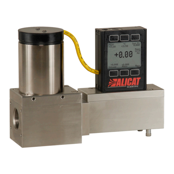
Large Valve Mass Flow Controller shown with a downstream valve configuration and connection port fittings MOUNTING MC Series Gas Flow Controllers have holes on the bottom for mounting to flat panels. See pages 48-51. Small valve controllers (MC Series) can usually be mounted in any position. -
Page 7: Plumbing
Make sure that the gas will flow in the direction indicated by the flow arrow. Standard MC Series Gas Flow Controllers have female inlet and outlet port connections. Welded VCR and other specialty fittings may have male ports. -
Page 8: Power And Signal Connections
POWER AND SIGNAL CONNECTIONS Power can be supplied to your controller through either the power jack (power jack not available on CSA/ATEX approved devices) or the 8 pin Mini-DIN connector. An AC to DC adapter which converts line AC power to DC voltage and current as specified below is required to use the power jack. -
Page 9: Input Signals
INPUT SIGNALS Analog Input Signal Apply analog input to Pin 4 as shown on page 8. For 6 Pin Locking Connector, DB9, DB15 and PROFIBUS Pin-outs see pages 73 to 81. Standard 0-5 Vdc is the standard analog input signal. Apply the 0-5 Vdc input signal to pin 4, with common ground on pin 8. -
Page 10: Rs-232 / Rs-485 Digital Input Signal
RS-232 / RS-485 Digital Input Signal To use the RS-232 or RS-485 input signal, connect the RS-232 / RS-485 Output Signal (Pin 5), the RS-232 / RS-485 Input Signal (Pin 3), and Ground (Pin 8) to your computer serial port as shown below. (See page 27 for details on accessing RS-232 / RS-485 input.) ... -
Page 11: Output Signals
RS-232 / RS-485 output.) Standard Voltage (0-5 Vdc) Output Signal MC Series flow controllers equipped with a 0-5 Vdc (optional 0-10 Vdc) will have this output signal available on Pin 6. This output is generally available in addition to other optionally ordered outputs. - Page 12 CAUTION! Do not connect this device to “loop powered’” systems, as this will destroy portions of the circuitry and void the warranty. If you must interface with existing loop powered systems, always use a signal isolator and a separate power supply. Purple (Ground) Yellow Unit A...
-
Page 13: Information For Alicat Tft (Color Display) Instruments
Information for Alicat TFT (Color Display) Instruments Alicat TFT (color display) instruments have a high contrast back-lit LCD display. TFT instruments operate in accordance with Alicat standard operating instructions for our monochrome menus and displays with the following differences. Multi-Color Display Color Codes: GREEN: Green labels identify the parameters and/or adjustments associated with the button directly above or below the label. -
Page 14: Displays And Menus
DISPLAYS AND MENUS The device screen defaults to Main display as soon as power is applied to the controller. Main The Main display shows pressure, temperature, set-point, volumetric flow and mass flow. SETPT PSIA 0.000 +13.60 +21.50 Pressing the button adjacent to a parameter will make that parameter SCCM the primary display unit. -
Page 15: Main
(PSIA). This can be converted to gage pressure (PSIG) by subtracting local atmospheric pressure from the absolute pressure reading: PSIG = PSIA – (Local Atmospheric Pressure) Gas Temperature: MC Series flow controllers measure the incoming temperature of the gas flow. The... -
Page 16: Mass Flow Rate
Mass Flow Rate: The mass flow rate is the volumetric flow rate corrected to a standard temperature and pressure (typically 14.696 psia and 25°C). This parameter is located in the lower middle of the display. It can be moved to the primary display by pushing the button below SCCM in this example. -
Page 17: Select Menu
SELECT MENU From Select Menu you can change the selected gas, interact with your RS-232 / RS-485 settings, read manufacturer’s data and access the control setup screen. Press the button next to the desired operation to bring that function to the screen. MODEL INFO ALICAT SCIENTI FIC... -
Page 18: Control Setup
CONTROL SETUP Control Setup is accessed by pressing the button below Control Setup on the Select Menu display. From this screen you can select your set-point source, choose a loop variable and adjust the PID terms. Press BACK to return to the Select Menu display. -
Page 19: Loop Variable
CAUTION! Never leave a Controller with a non-zero set-point if no pressure is available to make flow. The controller will apply full power to the valve in an attempt to reach the set-point. When there is no flow, this can make the valve very HOT! CONTROL SETUP (continued) LOOP VAR—The selection of what variable to close the loop on is a feature unique to... -
Page 20: Pid Tuning
PID TUNING PID Values determine the performance and operation of your proportional control valve. These terms dictate control speed, control stability, overshoot and oscillation. LOOP SETPT SETPT +0.0 SOURCE All units leave the factory with a generic tuning designed to handle most applications. If you encounter issues with valve stability, oscillation or speed, fine tuning these parameters may resolve the problem. - Page 21 The PID algorithm is an industry standard PID algorithm. It is divided into three segments. The first compares the process value to the set-point to generate a proportional error. The proportional error is multiplied by the ‘P’ gain, with the result added to the output drive register.
-
Page 22: Gas Select
GAS SELECT Gas Select is accessed by pressing the button below GAS SELECT on the Select Menu display. To select a gas, use the LN-UP and LN-UP LN-DN MODE LN-DN buttons to position the arrow in C2H6 Ethane front of the desired gas. Hydrogen Helium Press MODE and then PG-UP or PG-DN... -
Page 23: Communication Select
COMMUNICATION SELECT Access Communication Select by pressing the button above RS232 COMM or RS485 COMM on the Select Menu display. Unit ID – Valid unit identifiers are the UNIT ID BAUD 19200 letters A-Z and @. The identifier allows you to assign a unique address to each device so that multiple units can be connected to a single RS-232 or RS-485 computer port. -
Page 24: Miscellaneous
MISCELLANEOUS Miscellaneous is accessed by pressing the MISC button on the Select Menu display. NOTE: All Miscellaneous changes are recorded when you exit Miscellaneous. ZERO BAND refers to Display Zero Deadband. Zero deadband is a value below which the display jumps to zero. This deadband is often desired to prevent electrical noise from showing up on the display as minor flows or pressures that do not exist. -
Page 25: Manufacturer Data
MANUFACTURER DATA Manufacturer Data is accessed by pressing the MFG DATA button on the Select Menu display. The initial display shows the name MODEL and telephone number of the INFO manufacturer. ALI CAT SCI ENT I FI C Press MODEL INFO to show important Ph 520-290-6060 information about your flow device Fax 520-290-0109... -
Page 26: Mcv Controller Operating Notes
Solenoid valves for use with the MCV mass flow controller can be ordered from Alicat. Note: All standard MC Series device features and functions are available on the MCV Series and operate in accordance with the standard MC Series operating instructions. -
Page 27: Rs-232 Or Rs-485 Output And Input
RS-232 / RS-485 Output and Input Configuring HyperTerminal®: Open your HyperTerminal® RS-232 / RS-485 terminal program (installed under the “Accessories” menu on all Microsoft Windows® operating systems). 2. Select “Properties” from the file menu. 3. Click on the “Configure” button under the “Connect To” tab. Be sure the program is set for: 19,200 baud (or matches the baud rate selected in the RS-232 / RS-485 communications menu on the meter) and an 8-N-1-None (8 Data Bits, No Parity, 1 Stop Bit, and no Flow Control) protocol. -
Page 28: Sending A Set-Point Via Rs-232 Or Rs-485
2. You may now poll the unit by typing A followed by “Enter”. This does an instantaneous poll of unit A and returns the values once. You may type A “Enter” as many times as you like. Alternately you could resume streaming mode by typing *@=@ followed by “Enter”. - Page 29 The computer will respond by reading the current value for register 21 between 0-65535. It is good practice to write this value down so you can return to the factory settings if necessary. Enter the value you wish to try by writing the new value to register 21.
-
Page 30: Gas Select
Gas Select – The selected gas can be changed via RS-232 / RS-485 input. To change the selected gas, enter the following commands: In Streaming Mode: $$#<Enter> In Polling Mode: Address$$#<Enter> (e.g. B$$#<Enter>) Where # is the number of the gas selected from the table below. Note that this also corresponds to the gas select menu on the flow controller screen: Argon Methane... -
Page 31: Collecting Data
Collecting Data: The RS-232 / RS-485 output updates to the screen many times per second. Very short-term events can be captured simply by disconnecting (there are two telephone symbol icons at the top of the HyperTerminal® screen for disconnecting and connecting) immediately after the event in question. The scroll bar can be driven up to the event and all of the data associated with the event can be selected, copied, and pasted into Microsoft®... -
Page 32: Data Format
+014.70 +025.00 +02.004 +02.004 2.004 Air +014.70 +025.00 +02.004 +02.004 2.004 Air MC Series Mass Flow Controller Data Format Note: On units with the totalizer function, the sixth column will be the totalizer value, with gas select moving to a seventh column. -
Page 33: Sending A Simple Script File To Hyperterminal
Sending a Simple Script File to HyperTerminal® It is sometimes desirable to capture data for an extended period of time. Standard streaming mode information is useful for short term events, however, when capturing data for an extended period of time, the amount of data and thus the file size can become too large very quickly. - Page 34 14. The “Line Delay” box is defaulted to 0 milliseconds. This is where you will tell the program how often to read a line from the script file you’ve created. 1000 milliseconds is one second, so if you want a line of data every 30 seconds, you would enter 30000 into the box.
-
Page 35: Operating Principle
Operating Principle All M Series Gas Flow Meters (and MC Series Gas Flow Controllers) are based on the accurate measurement of volumetric flow. The volumetric flow rate is determined by creating a pressure drop across a unique internal restriction, known as a Laminar Flow Element (LFE), and measuring differential pressure across it. -
Page 36: Other Gases
Other Gases: M Series Flow Meters can easily be used to measure the flow rate of gases other than those listed as long as “non-corrosive” gas compatibility is observed. For ex- ample, a flow meter that has been set for air can be used to measure the flow of argon. The conversion factor needed for measuring the flow of different gases is linear and is simply determined by the ratio of the absolute viscosity of the gases. -
Page 37: Volumetric Flow And Mass Flow Conversion
Once the corrected mass flow rate at standard conditions has been determined and the density at standard conditions is known (see the density table at the back of this manual), a true mass flow can be calculated as detailed in the following example: Mass Flow Meter Reading = 250 SCCM (Standard Cubic Centimeters/Minute) Gas: Helium Gas Density at 25C and 14.696 PSIA = .16353 grams/Liter... -
Page 38: Standard Gas Data Tables
October 2005) may notice small discrepancies between the gas property tables of your old and new units. Alicat Scientific, Inc. has incorporated the latest data sets from NIST (including their REFPROP 7 data) in our products’ built-in gas property models. Be aware that the calibrators that you may be using may be checking against older data sets such as the widely distributed Air Liquide data. -
Page 39: Gas Viscosities, Densities And Compressibilities At
Viscosity* Density** Compressibility Short Long Form 25 deg C 25 deg C 25 deg C Number Form 14.696 PSIA 14.696 PSIA 14.696 PSIA 184.918 1.1840 0.9997 Argon 225.593 1.6339 0.9994 Methane 111.852 0.6569 0.9982 Carbon Monoxide 176.473 1.1453 0.9997 Carbon Dioxide 149.332 1.8080 0.9949... -
Page 40: Gas Viscosities, Densities And Compressibilities At
Viscosity* Density** Compressibility Short Long Form 0 deg C 0 deg C 0 deg C Number Form 14.696 PSIA 14.696 PSIA 14.696 PSIA 172.588 1.2927 0.9994 Argon 209.566 1.7840 0.9991 Methane 103.657 0.7175 0.9976 Carbon Monoxide 165.130 1.2505 0.9994 Carbon Dioxide 137.129 1.9768 0.9933... -
Page 41: Troubleshooting
TROUBLESHOOTING Display does not come on or is weak. Check power and ground connections. Please reference the technical specifications (pages 44-47) to assure you have the proper power for your model. Flow reading is approximately fixed either near zero or near full scale regardless of actual line flow. - Page 42 Averaging” on page 24. Jumps to zero at low flow. MC Series Controllers feature a programmable zero deadband. The factory setting is usually 0.5% of full scale. This can be adjusted between NONE and 3.2% of full scale. See page 24.
-
Page 43: Maintenance And Recalibration
Number, and Date of Manufacture are also available on the Model Info display (page 25). Cleaning: MC Series Flow Controllers require no periodic cleaning. If necessary, the outside of the controller can be cleaned with a soft dry cloth. Avoid excess moisture or solvents. -
Page 44: Mc And Mcr Series Technical Specifications
Technical Data for Micro-Flow and Ultra-Low Flow MC Mass Flow Controllers 0 to 0.5SCCM Full Scale through 0 to 50SCCM Full Scale The following specifications are for the standard configuration of the product. There are many options available. Specification Mass Controller Description Accuracy ±... - Page 45 Technical Data for Low Flow MC Mass Flow Controllers 0 to 100SCCM Full Scale through 0 to 20SLPM Full Scale The following specifications are for the standard configuration of the product. There are many options available. Specification Mass Controller Description Accuracy ±...
- Page 46 Technical Data for Moderate Flow MC Mass Flow Controllers 0 to 50SLPM Full Scale through 0 to 100SLPM Full Scale The following specifications are for the standard configuration of the product. There are many options available. Specification Mass Controller Description Accuracy ±...
- Page 47 Technical Data for High Flow MCR Mass Flow Controllers 0 to 100SLPM Full Scale through 0 to 3000SLPM Full Scale The following specifications are for the standard configuration of the product. There are many options available. Specification Mass Controller Description Accuracy ±...
-
Page 48: Mc And Mcr Series Dimensional Drawings
MC Series: 0 - 0.5SCCM 0 - 1SCCM 0 - 2SCCM 0 - 5SCCM 0 - 10SCCM 0 - 20SCCM 0 - 50SCCM ... - Page 49 MC Series: 0 - 50SLPM 0 - 100SLPM MCR Series: 0 - 100SLPM ...
- Page 50 MCR Series: 0 - 250SLPM MCR Series: 0 - 500SLPM ...
- Page 51 MCR Series: 0 - 2000SLPM MCR Series: 0 - 3000SLPM ...
-
Page 52: Mcv Technical Specifications
Technical Data for MCV Mass Flow Controller for Vacuum Applications 0 to 0.5SCCM Full Scale through 0 to 20SLPM Full Scale Specification MCV Mass Controller Description Accuracy ± (0.8% of Reading + 0.2% of Full Scale) At calibration conditions after tare ±... -
Page 53: Mcp Technical Specifications
Technical Data for MCP Moderate Flow Mass Flow Controllers 0 to 50SLPM Full Scale through 0 to 250SLPM Full Scale NOTICE: The following specifications are applicable to Alicat MCP Series Mass Flow Controllers only. Please note maximum pressure of 80 PSIG. Mass Specification Description... - Page 54 MCP Series: 50SLPM 100SLPM MCP Series: 250SLPM ...
-
Page 55: Mcs And Mcrs Series Technical Information
Technical Data for Alicat MCS and MCRS Series Mass Flow Controllers Alicat MCS and MCRS instruments are built for use with aggressive gases. For the most part, these instruments maintain the specifications of equivalently ranged MC and MCR Series devices. Standard Compatible Gas List for MCS and MCRS Controllers 98% Ar / 2% CO2 Argon... -
Page 56: Mcs And Mcrs Series Dimensional Drawings
MCS Series: 0 – 0.5SCCM 0 – 1SCCM 0 – 2SCCM 0 – 5SCCM 0 – 10SCCM 0 – 20SCCM 0 – 50SCCM MCS Series: 0 – 100SCCM 0 – 200SCCM 0 – 500SCCM 0 – 1SLPM 0 – 2SLPM 0 –... - Page 57 MCS Series: 0 – 50SLPM 0 – 100SLPM MCRS Series: 0 –...
- Page 58 MCRS Series: 0 – 250SLPM MCRS Series: 0 – 500SLPM 0 –...
- Page 59 MCRS Series: 0 – 2000SLPM MCRS Series: 0 – 3000SLPM ...
- Page 60 MCSV Series All ranges ...
-
Page 61: Mcq And Mcrq Series Technical Information
Technical Data for Alicat MCQ and MCRQ Series Mass Flow Controllers Alicat MCQ and MCRQ units are for high pressure applications. The flow rate is dependent on the pressure in that lower pressures will yield lower flow rates. The Q series devices are highly specialized and should only be ordered after consulting Alicat. -
Page 62: Profibus Technical Specifications
All other operating specifications are shown in the Technical Data page for standard Alicat instruments. All standard device features and functions are available and operate in accordance with the standard Alicat Scientific device operating manual provided with the device. Meter or Small Valve... -
Page 63: Devicenet™ Technical Specifications
Information for Alicat DeviceNet™ Compatible Instruments DeviceNet™ OVERVIEW Alicat DeviceNet™ compatible instruments support the Predefined Master/ Slave Connection Set. There are two connectors on the Alicat meter/controller. The DeviceNet™ standard M12 Micro Connector found on the top of the unit is required for DeviceNet™... - Page 64 0x1A (Mass Flow) Product Code See Product Codes Revision (Maj, Min) 0x01,0x01 Status 0x00 Serial Number 0x######## Product Name Alicat Scientific Inc MFC DeviceNet™ Object Class 0x03 DeviceNet™ Assembly Object Class 0x04 Connection Object Class 0x05 S-Device Supervisor Class 0x30...
- Page 65 Rev. No. Description Date DeviceNet™ MC10SLPM shown to provide DeviceNet™ connector dimensions only. Flow Alicat Scientific, Inc. 2045 N. Forbes Blvd. Suite 103 Tucson, AZ 85745 body and valve dimensions will vary with range.
-
Page 66: Option: Totalizing Mode
Option: Totalizing Mode Meters and Controllers can be purchased with the Totalizing Mode option. This option adds an additional mode screen that displays the total flow (normally in the units of the main flow screen) that has passed through the device since the last time the totalizer was cleared. - Page 67 Alicat Portable Meters and Gauges Alicat Portable Flow Meters and Gauges use a common 9 Volt battery located in the top section of your meter. Output signals from the flow meter are passed through the female connector on top of the flow meter. Turn the switch on top of the flow meter “off” when the meter is not in use.
-
Page 68: Option: Portable Meters And Gauges
Option: Remote Electronics for High Line or Gas Temperatures Some applications involve operating temperatures outside the standard Alicat device specifications. A solution using remote electronics is available. (This option is not applicable for liquid devices.) The flow body’s components are minimized to only the required sensors. -
Page 69: Accessory: Bb9 Multi-Drop Box
Accessory: BB9 Multi-Drop Box The BB9 Multi-Drop Box makes it convenient to wire multiple flow and/or pressure devices to a single RS-232 or RS-485 port. Now available with a USB interface! The Multi-Drop Box has nine 8 pin mini-DIN ports available. The ports are to be used with a standard double ended 8 pin mini-DIN (DC-62) style cable going from the box to each flow or pressure device. -
Page 70: Accessory: Flow Vision™ Sc
Accessory: Flow Vision™ SC Software Flow Vision™ SC is an intuitive software interface to help your test cycles run smoother and shorten your engineering time! Flow Vision™ SC lets you connect to and communicate with multiple Alicat units simultaneously. Now you can view virtual displays, control tabs, charts and data lines from every connected Alicat device on the same screen. -
Page 71: Accessories
Accessories Part Number Description FLOWVISIONSC Flow Vision™ SC software for interface with all Alicat instruments FLOWVISIONMX Flow Vision™ MX software for gas blending 9 position Multi-Drop Box BB9-I 9 position Multi-Drop Box, Industrial connectors PVPS24U Universal 100-240 VAC to 24 Volt DC Power Supply Adapter PS24VHC High current power supply for BB9 use with Large Valve Controllers PCASE... - Page 72 Accessories MNPT to Compression Fittings Filters & Elements FNPT-MNPT 10-32 - 1/8” SS-200-1-0157 10-32 5μ 510053 10-32 - 1/4” SS-400-1-0256 10-32 20μ 510054 1/8” - 1/8” SS-200-1-2 1/8” 20μ ILF-1/8-20 1/8” - 1/4” SS-400-1-2 1/4” 40μ ILF-1/4-40 1/8” - 3/8” SS-600-1-2 1/2”...
-
Page 73: Eight Pin Mini-Din Pin-Out
Eight Pin Mini-DIN Connector Pin-Outs If your Alicat Instrument was ordered with the standard Eight Pin Mini-DIN connection, please be sure to reference the following pin-out diagram. Standard 8 Pin Mini-DIN Pin-Out Mini-DIN Pin Function cable color... -
Page 74: Db9 Pin-Out Diagram
DB9 Pin-Outs If your Alicat instrument was ordered with a DB9 connection, please reference the following pin-out diagram. Standard DB9 Pin-Out Female Connector Function Inactive or optional 4-20mA Primary Output Signal Static 5.12 Vdc or Secondary Analog Output (4-20mA, 5Vdc, 10Vdc) ... -
Page 75: Profibus Pin-Out
PROFIBUS Pin-Outs If your Alicat Instrument was ordered with a PROFIBUS connection, please be sure to reference the following pin-out diagram. Power and Signal Connections: Connect to the device using two DB9 connectors. The female top connection is PROFIBUS. The male connection on the side is power and RS-232 or RS-485. Pin out diagrams for all PROFIBUS enabled Alicat devices are shown below. -
Page 76: Db15 Pin-Out Diagrams
DB15 Pin-Outs If your instrument was ordered with a DB15 connection, be sure to check the Calibration Label on the device and reference the appropriate pin-out diagram. The following pin-out chart describes the safest and generally compatible arrangement when connecting a non-Alicat DB15 wire to a DB15 equipped Alicat. Not all features may be available between brands, but the common denominators are featured in our DB15 offerings, along with some options for customization. - Page 77 DB15 Pin-Outs If your instrument was ordered with a DB15 connection, be sure to check the Calibration Label on the device and reference the appropriate pin-out diagram. The following pin-out chart describes the safest and generally compatible arrangement when connecting a non-Alicat DB15 wire to a DB15A equipped Alicat. Not all features may be available between brands, but the common denominators are featured in our DB15 offerings, along with some options for customization.
- Page 78 DB15 Pin-Outs If your instrument was ordered with a DB15 connection, be sure to check the Calibration Label on the device and reference the appropriate pin-out diagram. The following pin-out chart describes the safest and generally compatible arrangement when connecting a non-Alicat DB15 wire to a DB15B equipped Alicat. Not all features may be available between brands, but the common denominators are featured in our DB15 offerings, along with some options for customization.
- Page 79 DB15 Pin-Outs If your instrument was ordered with a DB15 connection, be sure to check the Calibration Label on the device and reference the appropriate pin-out diagram. The following pin-out chart describes the safest and generally compatible arrangement when connecting a non-Alicat DB15 wire to a DB15K equipped Alicat. Not all features may be available between brands, but the common denominators are featured in our DB15 offerings, along with some options for customization.
- Page 80 DB15 Pin-Outs If your instrument was ordered with a DB15 connection, be sure to check the Calibration Label on the device and reference the appropriate pin-out diagram. The following pin-out chart describes the safest and generally compatible arrangement when connecting a non-Alicat DB15 wire to a DB15H equipped Alicat. Not all features may be available between brands, but the common denominators are featured in our DB15 offerings, along with some options for customization.
- Page 81 DB15 Pin-Outs If your instrument was ordered with a DB15 connection, be sure to check the Calibration Label on the device and reference the appropriate pin-out diagram. The following pin-out chart describes the safest and generally compatible arrangement when connecting a non-Alicat DB15 wire to a DB15S equipped Alicat. Not all features may be available between brands, but the common denominators are featured in our DB15 offerings, along with some options for customization.
-
Page 82: Information For Csa And Atex Labeled Devices
Additional Information for Alicat CSA and ATEX Approved Devices See the following page for Special Conditions regarding the use of these units! II 3 G EEx nA IIC T4 Class I, Div. 2 Group A, B, C and D T4 24 Vdc, 0.800A max Class I, Zone 2 AEx nA IIC T4 WARNINGS:... - Page 83 HAZARDOUS. EXPLOSION HAZARD – SUBSTITUTION OF COMPONENTS MAY IMPAIR SUITABILITY FOR CLASS I, DIVISION 2. Alicat Scientific, Inc. Tucson, AZ USA Tel: 520-290-6060 www.Alicat.com USE of Alicat instruments (M, MS, MC, MCS, MCR, MCRS, P, PS, PC, PCS, PCR and PCRS product families only) in applications requiring ATEX Certification.
Need help?
Do you have a question about the MC Series and is the answer not in the manual?
Questions and answers