Table of Contents
Advertisement
Quick Links
Advertisement
Table of Contents

Related Manuals for Alicat Scientific EPCD Series


Summary of Contents for Alicat Scientific EPCD Series
- Page 1 Models EPCD · EPC...
- Page 2 Thank you for purchasing your OEM pressure controllers. Alicat Scientific World Headquarters india@alicat.com info-cn@alicat.com europe@alicat.com M/s Halma India Pvt. Ltd. alicat.com.cn Geograaf 24 C/O Avire India Pvt. Ltd. 2nd Floor, Block 63, No. 6921 EW Duiven Plot #A-147, Rd. #24...
- Page 3 ²...
-
Page 4: Getting Started
Getting Started Mounting EPC and EPCD-Series controllers have mounting holes for convenient mounting to flat panels. These controllers are position insensitive and can be mounted in any orientation. EPCD Caution: Minimize physical handling of the exposed circuit board of the EPC or EPCD while installing. - Page 5 Plumbing Process Ports Your instrument is shipped with plastic plugs fitted in the port openings. To lessen the chance of contaminating the flow stream do not remove these plugs until you are ready to install the device. Controllers with M5 (10-32) ports have O-ring face seals and require no sealant or tape.
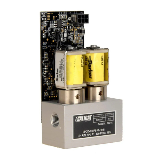
- Page 6 EPC Single Valve Controller Alicat Scientific EPC-Series Pressure Controllers incorporate a digital pressure gauge with a single control valve and circuitry. The integrated control algorithm measures the pressure, compares it with the setpoint, and adjusts the valve accordingly at 1000 times per second.
-
Page 7: Power And Signal Connections
Power and Signal Connections Power and communications are supplied through the 6 pin Molex Micro-Fit 3.0 connector: Function Power in 0–5 Vdc Optional: 1–5 Vdc or 0–10 Vdc output signal Ground (common for power, digital communications, and analog signals) Serial RS-232TX output signal Optional: RS-485 B Serial RS-232RX input signal Optional: RS-485 A... -
Page 8: Serial Communication
Analog Signals Analog Output Most devices include a primary analog output signal, which is linear over its entire range. For ranges that start at 0 Vdc, a zero-pressure condition is indicated at approximately 0.010 Vdc. Full scale pressure is indicated by the top of the range: 5 Vdc for 0-5 Vdc, 10 Vdc for 0-10 Vdc, and so on. -
Page 9: Polling Mode
Polling Mode Controllers are shipped in polling mode with a unit ID of A, unless requested otherwise. Each poll returns one line of data. To poll, simply enter its unit ID. Poll the device: [unit ID] a Example: (polls unit A) You can change the unit ID of a polling device by typing: [current unit ID]@=[desired unit ID]... - Page 10 Taring Taring pressure aligns the internal gauge pressure sensor with the current barometric pressure, and must be done with the EPC/EPCD pressure sensor open to atmosphere: [unit ID]p Tare gauge pressure: Example: ap Warning: Do not send tare commands on absolute pressure EPC/EPCD Collecting Pressure Data [unit ID]...
-
Page 11: Commanding A New Setpoint
Commanding a New Setpoint Before attempting to send setpoints to your flow controller serially, confirm that its setpoint source is set to serial by checking register 20. Read Register 20: [unit ID]r20 Example: ar20 For an EPC set to control forward pressure or an EPCD, if the value in register 20 is less than 16384, it’s already set up to receive setpoints serially. - Page 12 Sending Setpoints as Integers In this method, your controller’s full scale range (FS) is represented by a value of 64000, and a zero setpoint is represented by 0. To calculate your intended setpoint, use the following formula: Integer value = 64000 × [desired setpoint] ⁄...
-
Page 13: Pid Tuning
PID Tuning: Your flow controller uses a closed-loop algorithm to determine how to actuate its valve(s) in order to achieve the commanded setpoint. We have tuned these settings for your specific operating conditions, but changes to your process sometimes require on-site adjustments to maintain optimal control performance. - Page 14 Tuning the PD²I control algorithm The EPCD controller’s PD²I control algorithm is used to provide faster response, and high-performance swapping of the operation of the inlet and exhaust valve. This algorithm uses typical PI terms and adds a squared D term: ...
-
Page 15: Quick Command Guide
Quick Command Guide Note: Serial commands are not case-sensitive. For simplicity, we assume ✓ that the unit ID of the flow controller when not streaming is a in the listing that follows. a@=[desired unit ID] Change unit ID: Tare pressure: ap... -
Page 16: Maintenance
Maintenance Cleaning This device requires minimal maintenance. If necessary, the outside of the device can be cleaned with a soft dry cloth. Avoid excess moisture or solvents. The single most important thing that affects the life and accuracy of these devices is the quality of the gas being measured.
Need help?
Do you have a question about the EPCD Series and is the answer not in the manual?
Questions and answers