
Related Manuals for Nanni N5.160 CR2


Summary of Contents for Nanni N5.160 CR2
- Page 1 NANNI MARINE ENGINE OPERATOR MANUAL DGBXXT090013 ENGINE N5.160 CR2 N5.180 CR2 N5.200 CR2 N5.230 CR2...
-
Page 3: Q00 Tracked Changes
TRACKED CHANGES TRACKED CHANGES CODE INDEX DATE INITIALS NATURE OF TRANSLATIONS PAGES DGBXXT09013 05/2019 Create Please note all changes and pages associated. For further clarity, please add a line in front of each change. -
Page 5: Table Of Contents
SUMMARY Table des matières WATER IN FUEL TRACKED CHANGES MICROORGANISMS IN FUEL TRACKED CHANGES INERT IMPURITIES IN FUEL SUMMARY DIESEL LUBRICANTS INTRODUCTION PRECAUTIONS TO UNDERTAKE INTRODUCTION OILS RECOMMENDED OR AUTHORIZED ABOUT THIS MANUAL GENERALITIES CONTENT & UPDATES OILS VISCOSITY S02 SAFETY CORRESPONDENCE BETWEEN API AND ACEA OILS SUMMARY SAFETY SIGNALS... - Page 6 COMPONENTS OIL LEVEL - ADDING ENGINE OIL COMPONENTS DRAINING THE ENGINE OIL ENGINE MAIN COMPONENTS CHANGING THE OIL FILTER ENGINE VIEWS N5.160 CR2 - N5.180 CR2 - N5.200 COOLING SYSTEM CR2 - N5.230 CR2 OVERVIEW S07 STARTING & RUNNING COOLANT...
-
Page 7: S01 Introduction
If there are any equipment details that are not shown or described in this Manual, or if you have any question regarding the operation of any equipment, your authorized Nanni dealer will be glad to inform you of correct care and operating procedures. -
Page 8: About This Manual
Please ensure that this Manual is always kept in the authorized Nanni Dealer will be glad to inform you of boat. It should always be available to anyone else using correct care and operating procedures. -
Page 9: S02 Safety
SAFETY SUMMARY SAFETY SUMMARY SAFETY SIGNALS SAFETY INFORMATION REPLACEMENT OF MISSING OR DAMAGED SAFETY SIGNS READ SAFETY INSTRUCTIONS ENGINE-GENSET SAFETY ICONS SAFETY PRECAUTIONS HOT EXHAUST PRECAUTIONS WORK IN VENTILATED AREA WASTE DISPOSAL UNWANTED ENGINE START SAFE MAINTENANCE PRACTICE WORK IN CLEAN AREA PROTECTIVE CLOTHING SERVICE ENGINES SAFELY PROPER USE OF TOOLS... -
Page 10: Safety Signals
Carefully read all safety messages in this manual and on If you do not understand any part your genset safety signs. of this document and need assistance, contact your Nanni Keep safety signs in good condition. Be sure new representative. equipment components and repair parts include the current safety signs. -
Page 11: Engine-Genset Safety Icons
SAFETY ENGINE-GENSET SAFETY ICONS Indicates the oil drain orifice. Some stickers are fixed directly on the engine. They are intended to help you to quickly identify the location of certain components and avoid possible hazards when working on the engine. Ensure that these stickers are always visible and replace them if torn or washed up. -
Page 12: Safety Precautions
SAFETY SAFETY PRECAUTIONS UNWANTED ENGINE START Avoid possible injury or death from engine runaway. Do not start engine by shorting HOT EXHAUST PRECAUTIONS across starter motor solenoid terminals posts. Engine will start if normal Servicing machine or attachments with circuitry is bypassed. Start engine from engine running can result in serious operator’s seat. -
Page 13: Service Engines Safely
SAFETY SERVICE ENGINES SAFELY PROPER LIFTING EQUIPMENT Tie long hair behind your head. Do not wear a necktie, scarf, loose clothing, or necklace when you work near moving parts. If these items were to get caught, severe injury could result. Remove rings Lifting heavy components incorrectly can cause severe and other jewelry to prevent electrical injury or equipment damage. -
Page 14: Staying Clear Of Rotating Drivelines
SAFETY STAYING CLEAR OF ROTATING Common Rail (HPCR) fuel system. Only technicians familiar with this type of system can perform repairs. DRIVELINES Consult your engine representative. Entanglement in rotating driveline can cause serious injury or death. Keep all AVOID HIGH-PRESSURE FLUIDS shields in place at all times. -
Page 15: Welding Near Electronic Control Unit (Ecu)
SAFETY WELDING NEAR ELECTRONIC CONTROL HANDLE FUEL SAFELY - AVOID FIRES UNIT (ECU) Handle fuel with care: it is highly flammable. Do not refuel the engine while smoking or when near open flame If welding is required around the engine, or or sparks.Always stop engine before refueling. -
Page 16: Prevent Battery Explosions
SAFETY Always remove grounded (-) battery clamp first and replace grounded clamp last. Sulfuric acid in battery WARNING ! electrolyte is poisonous and strong enough to burn skin, eat holes in clothing, and cause blindness if splashed into eyes. Battery posts, terminals, and related accessories contain Avoid hazards and acid burns in : lead and lead compounds. -
Page 17: S03 Fluids
FLUIDS SUMMARY Table des matières FLUIDS SUMMARY FUELS DIESEL FUEL SULPHUR CONTENT WINTER DIESEL WATER IN FUEL MICROORGANISMS IN FUEL INERT IMPURITIES IN FUEL DIESEL LUBRICANTS PRECAUTIONS TO UNDERTAKE OILS RECOMMENDED OR AUTHORIZED GENERALITIES OILS VISCOSITY CORRESPONDENCE BETWEEN API AND ACEA OILS COOLANTS COOLANT DRAIN INTERVALS WATER PROPERTIES... -
Page 18: Fuels
DIESEL FUEL engine damage and will void all contractual warranties and responsabilities from Nanni Industries. Diesel approved by Nanni Industries on the engines of the firm are as follows : • EN 590 (Europe), WATER IN FUEL •... -
Page 19: Inert Impurities In Fuel
Due to their inertia, hot oils retain a higher temperature of the engine which is not covered by Nanni Industries than expected. A hot oil can cause severe burns on warranty. -
Page 20: Oils Viscosity
BioDiesel blends greater than B20. Oil analysis may allow longer service intervals. fuel economy. Refer to the expertise of the local Nanni Industries representative regarding the oil that best Use only approved oil types. -
Page 21: Coolants
This can lead to the invalidation of Nanni’s warranty for faults and damage caused by the use of Water used in the cooling system should meet the inappropriate coolant. -
Page 22: Other Coolants
Tap clean water may be used as coolant substitute from corrosion. in emergency situations only. Contact a Nanni representative as soon as it is possible for assistance. Get this water flushed as soon as possible. -
Page 23: Disposing Of Waste Fluids
Inquire on the proper way to recycle dispose of waste from your local environmental or recycling center, or from your Nanni engine representative or service dealer. -
Page 24: Annex
FLUIDS ANNEX ANNEX 1. VOLUME OF GLYCOL % by volume of Glycol Cooling Ice slush starts system capacity to form at °C in dm Ice slush starts -5.8 -11.2 -34.6 to form at °F Ethylene glycol (litre) Volume of glycol below 30% to be avoided. -
Page 25: S04 Engine Warranty
The engine type can be exhaust emission certified. It be quoted when ordering service and replacement parts. means that Nanni guarantees that all engines of the The engine identification plate is as follow : same type that are manufactured are approved and certified by the authorities in accordance with different exhaust emissions standards. -
Page 26: Engine Responsability
Nanni representative. NOTE ! Late or improper maintenance or use of spare parts other than Nanni original spare parts will invalidate Nanni’s responsibility for the engine accordance with homologation and will void the Warranty. -
Page 27: Epa Warranty
Directive 2004/26/EC. The EU engine family is listed on the Emissions Label. When installed in accordance with the manufacturer’s instructions, Nanni Industries Marine Diesel Propul- sion Engines without integral exhaust certified under Directive 97/68/EC as amended by Directive 2004/26/... -
Page 28: S05 Instruments
C5 PANEL C5 STANDARD SEPARATE INSTRUMENTS C5 OPTIONAL SEPARATE INSTRUMENTS C5 TACHOMETER & LCD DISPLAY ALTERNATOR CHARGE INDICATOR STARTER SWITCH OIL PRESSURE INDICATOR COOLANT TEMPERATURE INDICATOR FUEL LEVEL INDICATOR WATER LEVEL INDICATOR TRIM INDICATOR RUDDER INDICATOR ELECTRONIC INSTRUMENTS NANNI CONTROL PANELS... -
Page 29: Generalities
IGNITION position (ON). Instruments panels offer from Nanni Industries is very wide and depends also from the type of engine and the technology involved in it. That is, some panels are solely dedicated to one engine only. Here below, the reader will find a view of the current Nanni instruments panels range, followed by a table showing engines and relevant(s) instruments panel. -
Page 30: C4 Panel
This warning lamp comes on and the alarm sounds when the coolant temperature is too high. DANGER ! Nanni assembled panels are plug and play directly to the engine via an extension cable. Never open the coolant filler cap or any plug of the cooling system when the engine is warm. -
Page 31: Preheating
To operate an engine when oil pressure is too lowcan lead system or beacuse the alternator belt is slack. to a severe engine damage. Do not operate the engine if the problem persist and contact a Nanni representative as soon as possible. CAUTION ! -
Page 32: C5 Panel
Start : The starter motor is energized to crank the engine; the key returns to the ON position as soon as released. See your Nanni representative for these instruments. Some of them might be available on order only. The function of panel instruments is described in detail... -
Page 33: Oil Pressure Indicator
To operate an engine when oil pressure is too low, can lead to a severe engine damage. Do not operate the engine if the problem persist and contact a Nanni representative as soon as possible. WATER LEVEL INDICATOR Displays the water level remaining in the water tank for amenities (when equiped). -
Page 34: Rudder Indicator
Never start nor run the engine when the drive is in the lift range. Nanni SI.4 Electronic control displays is connected to the engine through a dedicated harness. See your Nanni RUDDER INDICATOR representative for more information. -
Page 35: Nanni Control Panels
INSTRUMENTS NaNNi CoNtrol PaNels Eco 4 Eco 4 w/o key A4 -12 V A4 -24 V w/o key A4 Fly A4 Fly-loose instr A4 loose instr A4 w/o key A5 Fly loose instr B4 - 12 V B4 + Indicator fuel 12 V... - Page 36 INSTRUMENTS T8V. T8V. T8V. NaNNi CoNtrol PaNels MECA MECA Eco 4 Eco 4 w/o key A4 -12 V A4 -24 V w/o key A4 Fly A4 Fly-loose instr A4 loose instr A4 w/o key A5 Fly loose instr B4 - 12 V...
-
Page 37: S06 Components
COMPONENTS SUMMARY SUMMARY COMPONENTS ENGINE MAIN COMPONENTS ENGINE VIEWS N5.CR2... -
Page 38: S06 Components
COMPONENTS ENGINE MAIN COMPONENTS NOTE ! Minor engine details may not be exactly as shown. Some components may not be part of the engine ordered. Not binding pictures. COMPONENTS Alternator Alternator Belt Belt cover Starter Air filter Fuel filter Fuel injection pump Heat exchanger Heat exchanger drain plug Raw water pump... -
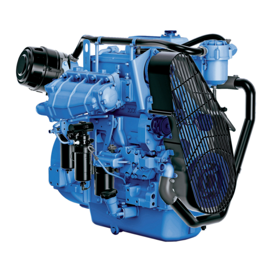
Page 39: Engine Views N5.160 Cr2 - N5.180 Cr2 - N5.200 Cr2 - N5.230 Cr2
COMPONENTS ENGINE VIEWS N5.160 CR2 - N5.180 CR2 - N5.200 CR2 - N5.230 CR2... - Page 40 NOTES...
-
Page 41: S07 Starting & Running
STARTING & RUNNING SUMMARY TABLE DES MATIÈRES STARTING & RUNNING SUMMARY BEFORE STARTING ENGINE INSTALLATION FUEL SYSTEM RAW WATER SYSTEM ELECTRICAL SYSTEM CHECK BEFORE STARTING STARTING THE ENGINE COLD WEATHER OPERATION ENGINE START ENGINE STARTED STARTING WITH BOOSTER BATTERIES ENGINE RELUCTANT TO START IDLING ENGINE NORMAL ENGINE OPERATION BREAK IN... -
Page 42: Before Starting
STARTING & RUNNING BEFORE STARTING RAW WATER SYSTEM The raw water system allows to cool the engine coolant and the exhaust gas. ENGINE INSTALLATION Raw water is drawn into the heat exchanger by the engine raw water pump. The raw water is drained via the See Installation manual exhaust elbow, where it is mixed with exhaust gases. -
Page 43: Check Before Starting
Turn on the engine coolant heater for a minimum of 2 required. hours before starting the engine. Additional information on cold weather operation is available from your Nanni 9. Check there are no fuel, oil, coolant or water leaks. engine distributor or authorized servicing dealer. -
Page 44: Engine Start
STARTING & RUNNING ENGINE START 4. Press the Start button halfway (position 1/2) to start preheating. Hold the button for 10 to 20 seconds, depending on ambient temperature to preheat the With key Type 4 : engine. POSITION 2 1. Move the control lever to the neutral position. POSITION 1/2 : preheating POSITION 1 NEUTRAL... - Page 45 STARTING & RUNNING Electronic type 5: Turn the ignition key to the ON position. On Eco 4, only the oil pressure and battery charge lamp light on. It is not required to start the engine for system initializa- tion. The tachometer will start an autimatic self-test at every powering up.
-
Page 46: Engine Started
STARTING & RUNNING ENGINE STARTED ENGINE RELUCTANT TO START To insure adequate lubrication, operate engine at or If a water lift (water lock) muffler is installed on the below 1200 rpm with no load for 1-2 minutes. Extend exhaust line, excessive cranking could cause seawater this period to 2–4 minutes at freezing or sub-zero to enter the cylinders and damage the engine. -
Page 47: Normal Engine Operation
Any mechanical power taken from the engine from a PTO reduces the power delivered to the propeller. The use of a PTO should always be studied and approved by the R&D department of Nanni Industries S.A.S France. Contact your Nanni dealer for more informations. -
Page 48: Remote Control
Check the instruments and warning lamps after starting, neutral position. and regularly when cruising. Consult the boat builder or your Nanni dealer if you are not sure about the operation of the remote control. -
Page 49: Cruising Speed
STARTING & RUNNING CRUISING SPEED MANOEUVRING A recommended engine speed is given in the TECHNICAL DATA section to help you to set your cruising speed. WARNING ! NOTE ! Shifting at high speed can damage both the engine and the transmission and be dangerous for passengers. Always consider sailing conditions and load of the boat to set the cruising speed. -
Page 50: Trolling Valve
STARTING & RUNNING TROLLING VALVE The Trolling valve system allows to reduce the rotation speed of the propeller below its speed when the engine is at idle. The boat speed is reduced by 30% to 70%. CAUTION ! The Trolling valve system must never be used for manoeuvring. -
Page 51: After Running
STARTING & RUNNING AFTER RUNNING AFTER STOPPING THE ENGINE STOPPING THE ENGINE CAUTION ! Even after the engine has stopped, some components CAUTION ! and fluids will remain hot and under pressure for several minutes. As far as possible, limit works on the engine Never stop the engine by using the main switch. -
Page 52: Anchoring
STARTING & RUNNING ANCHORING If the boat is not going to be used for some time but is being left in the water, the engine must be run to operating temperature at least once every 2 weeks. This prevents corrosion in the engine. When the boat is at anchor or in port for an extended period of time, vegetation may develop on the hull, the keel, the drive, the rudder, the propeller, etc. -
Page 53: S08 Maintenance
MAINTENANCE SUMMARY MAINTENANCE SUMMARY ABOUT MAINTENANCE GENERALITIES CONTROL CABLES TURBOCHARGER EXHAUST SYSTEM ENGINE MOUNTS CHECK AIR INTAKE CHECK THE AIR FILTER CLEANING THE AIR FILTER VENT CRANKCASE FILTER REPLACING CRANKCASE VENT FILTER FUEL SYSTEM DRAIN WATER IN FUEL PREFILTER REPLACING THE FUEL FILTER DRAINING WATER FROM FUEL FILTERS LUBRICATION SYSTEM OIL LEVEL - ADDING ENGINE OIL... -
Page 54: Maintenance
During the warranty period, it is essential to get any work carried out by a Nanni authorized workshop. Furthermore, any service should be registered in the Nanni after-sale system. -
Page 55: Maintenance
MAINTENANCE MAINTENANCE PÉRIODICITÉ Every Every Every Daily Maintenance 250 hours or 500 hours or 2000 hours or COMPONENTS 100 hours ( 1 year ( 2 years ( 2 years ( FUEL CIRCUIT Water in fuel - Pre-filter / Filter Draining Fuel Filter Fuel injectors - Check Cut out and misfiring with Diagnostic Tool ( Mechanical Fuel injectors... -
Page 56: Generalities
MAINTENANCE GENERALITIES CONTROL CABLES The engine rpm and the gearbox shift command may be controlled by mechanical control cables connected to WARNING ! the control lever. Adjust the tightness of the cable as required. If any Perform maintenance operations having the engine defect appears (rust, crack, etc.), the control cable must stopped and cold. -
Page 57: Turbocharger
MAINTENANCE TURBOCHARGER TURBO SERVICE Engine turbochargers are designed to provide long years of trouble free service, which if required, can CAUTION ! only be performed by a specialized workshop. In view to maintain turbochargers performances for as long as possible, some basic rules must be followed. A turbocharger is an exhaust-driven mechanical device Changing or cleaning the air filters on a regular basis is that boost engine power by pumping more air into the... -
Page 58: Exhaust System
Front engine mounts (A) only are available from Nanni Diesel. Exhaust resistance must be as low as possible in order to prevent a decrease in power, however exhaust noise must be kept at an acceptable level. Careful design is required to reconcile these two conflicting factors. -
Page 59: Air Intake
MAINTENANCE AIR INTAKE CLEANING THE AIR FILTER Specific tool For best results, order the NANNI filter cleaning kit: WARNING ! Number Description Illustration 970317077 Kit air filter cleaner EN, ESP, SUOMI Carry out these operations when the engine is stopped... -
Page 60: Vent Crankcase Filter
MAINTENANCE VENT CRANKCASE FILTER REPLACING CRANKCASE VENT FILTER The top of the crankcase filter is equiped with a sensor Crankcase Ventilation is a system that was developed to poping up when the filter is full and needs to be replaced. remove harmful vapors from the engine and to prevent If the indicator has not surfaced, there is no need to those vapors from being expelled into the atmosphere. -
Page 61: Fuel System
Any work on the fuel injection system must be carried 5. Open the fuel butterfly (control) valve. out by a authorized Nanni technician. 6. Bleed the fuel system (see in the following Check regularly the condition of the components of the paragraphs). -
Page 62: Replacing The Fuel Filter
MAINTENANCE REPLACING THE FUEL FILTER NOTE ! Locators on fuel filter canisters must be indexed properly Primary fuel filter and secondary fuel filter must both be with slots in mounting base for correct installation. replaced whenever audible alarm sounds and diagnostic trouble code indicates a plugged filter (fuel supply pressure moderately/extremely low). -
Page 63: Lubrication System
MAINTENANCE LUBRICATION SYSTEM OIL LEVEL - ADDING ENGINE OIL Check the engine and transmission oil level before starting the engine. The oil level should be within the range indicated on the dipstick, between the Mini and CAUTION ! Maxi level. HOW TO CHECK THE OIL LEVEL: Never over-fill the engine oil crankcase. -
Page 64: Draining The Engine Oil
MAINTENANCE DRAINING THE ENGINE OIL CHANGING THE OIL FILTER STANDARD DRAINING: Replace the oil filter every time the engine oil is drained. 1. Start the engine and let it warm few minutes to render oil more fluid to ease suction. 2. -
Page 65: Cooling System
• The RAW WATER CIRCUIT which cools the coolant via an heat exchange with raw water. Nanni engines are delivered as standard with an heat exchanger, in which the coolant is cooled by heat exchange with raw water taken from a sea cock. -
Page 66: Coolant Level
2. Unscrew the filler cap (A) on the exchanger tank on supplied from a general hardware store. picture below. A specific boiler kit is available from Nanni Industries. 3. You may top-up with clean water only, if amount to Please contact your nearest Nanni representative for fill is very remote. -
Page 67: Draining The Coolant Circuit
MAINTENANCE DRAINING THE COOLANT CIRCUIT HOW TO FILL THE COOLANT SYSTEM: 1. Stop the engine and remove the key from the panel. 2. Put a container under the drain plug (B) of the engine to collect coolant. Unscrew the plug and remove the filler cap (A) on top. -
Page 68: Removing And Installing Thermostats
MAINTENANCE REMOVING AND INSTALLING THERMOSTATS TESTING THERMOSTATS 1. Remove thermostats. 1. Visually inspect area around thermostat housing and cover for leaks. 2. Visually inspect thermostats for corrosion or damage. Replace thermostats as a matched set as necessary. 2. Remove coolant tank pressure cap and partially drain coolant system. - Page 69 If you suspect that your heat exchanger core is defective, have your authorized Nanni representative to handle this task. Replace the heat exchanger core as required. Remove and thoroughly clean with water the manifold/ heat exchanger housing if needed.
-
Page 70: Raw Water System
MAINTENANCE RAW WATER SYSTEM SIPHON BREAKER DANGER ! DANGER ! Close the sea cock before any operation on the siphon When the boat is on the water, water can flow into the breaker. boat via components located below the waterline. Close the raw water cock (if fitted) or prevent water discharge before working on the raw water system. -
Page 71: Extract The Raw Water Pump Impeller
MAINTENANCE EXTRACT THE RAW WATER PUMP IMPELLER 5. Install pump overhaul kit. 6. Install lock washer (E) and hex nut (F) finger tight and insure key is properly in place. CAUTION ! 7. Tighten hex nut to specifications : 68 Nm (50 lb.-ft.). 8. -
Page 72: Cleaning The Raw Water Filter
MAINTENANCE CLEANING THE RAW WATER FILTER RAW WATER SYSTEM - DRAINING The model of prefilter can vary according the boat as the raw water filter is an optional extra not in the scope of WARNING ! supply of the engine. These instructions are given as an example only. -
Page 73: Raw Water System - Cleaning
7. At this stage, the raw circuit is alleged to be cleaned up. If deposits and salt crystals are still present, consult your Nanni representative. Do not add up cleaners additives like caustic soda, as aluminium parts are prone to fast corrosion if harshly cleaned. -
Page 74: Electrical System
MAINTENANCE ELECTRICAL SYSTEM DANGER ! Stop the engine and switch off the main breaker before working on the electrical system. Isolate shore current to any accessories supplying the engine. CAUTION ! The main breaker switch must remain ON when the engine is operating. -
Page 75: Propulsion Engine Wiring Harness
MAINTENANCE PROPULSION ENGINE WIRING HARNESS A—10-Way Molded Connector B—Red (Alternator) C—Black (Alternator) D—Yellow and Red (Alternator) E—Pink/Black and Black (Fuel Filter/Water Separator) F—Yellow/Red (Start Circuit Relay) G—Black (Start Circuit Relay) H—Red (Start Circuit Relay) J— Red (Fuse Holder) K—Black (Ground) L—... -
Page 76: Propulsion Engine Wiring
MAINTENANCE PROPULSION ENGINE WIRING A—Alternator B—20-Amp Fuse with Holder C—Start Circuit Relay D—Fuel Filter/Water Separator E—Starting Motor F— Fuel Shut-Off Solenoid G—Battery H—Tachometer Pick-up I— Coolant Temperature Sensor J— Engine Oil Pressure Sensor K—Spare Sensor L— 10-Way Molded Connector... -
Page 77: Instruments Panel
MAINTENANCE INSTRUMENTS PANEL... -
Page 78: Battery
BATTERY ELECTROLYTE LEVEL To charge two independent batteries with a single alternator, an isolator is available as an option on most engines. Contact an authorized Nanni representative. DANGER ! KEEP CLEAN THE BATTERY Never touch the battery electrolyte with bare fingers. -
Page 79: Electrolyte Level Check
MAINTENANCE ELECTROLYTE LEVEL CHECK ALTERNATOR BELT The engine alternator is driven by a belt through pulleys. In general, detailed informations for service provided by These components must be in good order at all times battery manufacturers are very scarce. As a conservative in view for the alternator to provide electricity, among rule, electrolyte level must always be above the top of others, to the engine, to the battery, to the engine control... - Page 80 MAINTENANCE TO REPLACE THE BELT: CHECKING THE BELT TENSION WITH A SMARTPHONE: 1. Stop the engine and remove the key from the panel. Nowadays, it is possible to check a belt tension in using an application on a smartphone. Several applications 2.
-
Page 81: Miscellaneous
MAINTENANCE MISCELLANEOUS CAMSHAFT TIMING From the two camshafts down to the crankshaft, N5.160 engine timing is ordered through a gear system. The complete assembly is service free. Inspection is occuring only during a major service on the engine. -
Page 82: S09 Storage
STORAGE SUMMARY Table des matières STORAGE SUMMARY LONG TERM STORAGE LONG TERM STORAGE PROCEDURE RESTARTING THE ENGINE BATTERY... -
Page 83: Long Term Storage
All these operations 9. Drain any water and contaminants from the fuel tank. should be carried out by a Nanni authorized workshop. 10. Fill totally the fuel tank. 11. Remove the air filter. Secure all air intake with clean clothes. -
Page 84: Restarting The Engine
STORAGE RESTARTING THE ENGINE BATTERY When storing the engine, adjust the battery electrolyte 1. Perform external cleaning of the engine and control level and store it in a dry place at room temperature. its condition. Recharge the battery as often as possible to extend its 2. -
Page 85: S10 Troubleshooting
CAUTION ! If the engine does not function properly, use the following chart to identify the cause. If the cause of trouble can not be found, contact to Nanni authorized workshop. NOTE ! Some components may not be part of the engine orderes. This list is not exhaustive and is only ab assistance in case of emergencies. - Page 86 TROUBLESHOOTING Lack of fuel Air in fuel system Fuel filter fouled or clogged Fuel do not meet specified standard Water/contaminants in fuel Valve clearance is wrong * Low compression * Insufficient battery charge / Defective battery Faulty electrical cables contact Faulty starter or starter switch * Tripped fuse / Main switch is open Transmission is damaged*...
- Page 87 Moteur de propulsion PROPULSION ENGINE N5.160CR2 FiCHe teCHniQue DATA SHEET CARACTERISTIQUES GENERALES GENERAL DATA Base moteur John Deere Engine Base Configuration 4 cylindres en ligne Configuration 4 cylinders in line Type 4 temps Diesel Type 4 strokes Diesel Nombre de soupapes par cylindre N°...
- Page 88 N5.160CR2 119 kW [162 cv] SYSTEME DE LUBRIFICATION (suite) LUBRIFICATION SYSTEM (continued) litres Capacité d'huile sans filtre, angle 0° Oil quantity excluding filter @ 0° angle gal US volant vers le bas Angle d'installation ° front down maxi admissible Maximum permitted volant vers le haut °...
- Page 89 N5.160CR2 119 kW [162 cv] SYSTEME DE REFROIDISSEMENT COOLING SYSTEM l/min Débit - liquide de refroidissement Coolant circulation pump flow gal US/min 52.3 l/min Débit - eau brute Raw water pump flow gal US/min Chaleur total dégagée à puissance nominale Total heat rejection at rated speed BTU/min 73.4...
- Page 90 Uninterrupted full power NaNNi iNdustries s.a.s. Spécifications selon ISO 3046. Document non contractuel. Soucieuse d’améliorer la qualité de ses produits, Nanni se 11, Avenue Mariotte - Zone Industrielle réserve le droit de modifier, sans préavis, toutes caractéris- tiques énoncées dans ce document. Les images et schémas 33260 La Teste - France peuvent représenter des éléments non-standards.
- Page 91 Moteur de propulsion PROPULSION ENGINE N5.180CR2 FiCHe teCHniQue DATA SHEET CARACTERISTIQUES GENERALES GENERAL DATA Base moteur John Deere Engine Base Configuration 4 cylindres en ligne Configuration 4 cylinders in line Type 4 temps Diesel Type 4 strokes Diesel Nombre de soupapes par cylindre N°...
- Page 92 N5.180CR2 134 kW [182 cv] SYSTEME DE LUBRIFICATION (suite) LUBRIFICATION SYSTEM (continued) litres Capacité d'huile sans filtre, angle 0° Oil quantity excluding filter @ 0° angle gal US volant vers le bas Angle d'installation ° front down maxi admissible Maximum permitted volant vers le haut °...
- Page 93 N5.180CR2 134 kW [182 cv] SYSTEME DE REFROIDISSEMENT COOLING SYSTEM l/min Débit - liquide de refroidissement Coolant circulation pump flow gal US/min 54.9 l/min Débit - eau brute Raw water pump flow gal US/min Chaleur total dégagée à puissance nominale Total heat rejection at rated speed BTU/min 82.5...
- Page 94 NaNNi iNdustries s.a.s. Spécifications selon ISO 3046. Document non contractuel. Soucieuse d’améliorer la qualité de ses produits, Nanni se 11, Avenue Mariotte - Zone Industrielle réserve le droit de modifier, sans préavis, toutes caractéris- tiques énoncées dans ce document.
- Page 95 Moteur de propulsion PROPULSION ENGINE N5.200CR2 FiCHe teCHniQue DATA SHEET CARACTERISTIQUES GENERALES GENERAL DATA Base moteur John Deere Engine Base Configuration 4 cylindres en ligne Configuration 4 cylinders in line Type 4 temps Diesel Type 4 strokes Diesel Nombre de soupapes par cylindre N°...
- Page 96 N5.200CR2 149 kW [203 cv] SYSTEME DE LUBRIFICATION (suite) LUBRIFICATION SYSTEM (continued) litres Capacité d'huile sans filtre, angle 0° Oil quantity excluding filter @ 0° angle gal US volant vers le bas Angle d'installation ° front down maxi admissible Maximum permitted volant vers le haut °...
- Page 97 N5.200CR2 149 kW [203 cv] SYSTEME DE REFROIDISSEMENT COOLING SYSTEM l/min Débit - liquide de refroidissement Coolant circulation pump flow gal US/min 56.8 l/min Débit - eau brute Raw water pump flow gal US/min 62.8 Chaleur total dégagée à puissance nominale Total heat rejection at rated speed BTU/min Capacité...
- Page 98 NaNNi iNdustries s.a.s. Spécifications selon ISO 3046. Document non contractuel. Soucieuse d’améliorer la qualité de ses produits, Nanni se 11, Avenue Mariotte - Zone Industrielle réserve le droit de modifier, sans préavis, toutes caractéris- tiques énoncées dans ce document.
- Page 99 Moteur de propulsion PROPULSION ENGINE N5.230CR2 FiCHe teCHniQue DATA SHEET CARACTERISTIQUES GENERALES GENERAL DATA Base moteur John Deere Engine Base Configuration 4 cylindres en ligne Configuration 4 cylinders in line Type 4 temps Diesel Type 4 strokes Diesel Nombre de soupapes par cylindre N°...
- Page 100 N5.230CR2 168 kW [228 cv] SYSTEME DE LUBRIFICATION (suite) LUBRIFICATION SYSTEM (continued) litres Capacité d'huile sans filtre, angle 0° Oil quantity excluding filter @ 0° angle gal US volant vers le bas Angle d'installation ° front down maxi admissible Maximum permitted volant vers le haut °...
- Page 101 N5.230CR2 168 kW [228 cv] SYSTEME DE REFROIDISSEMENT COOLING SYSTEM l/min Débit - liquide de refroidissement Coolant circulation pump flow gal US/min 60.7 l/min Débit - eau brute Raw water pump flow gal US/min Chaleur total dégagée à puissance nominale Total heat rejection at rated speed BTU/min 97.8...
- Page 102 NaNNi iNdustries s.a.s. Spécifications selon ISO 3046. Document non contractuel. Soucieuse d’améliorer la qualité de ses produits, Nanni se 11, Avenue Mariotte - Zone Industrielle réserve le droit de modifier, sans préavis, toutes caractéris- tiques énoncées dans ce document.
- Page 104 NaNNi iNdustries s.a.s. 11, Avenue Mariotte 33260 La Teste France Tel: +33 (0)5 56 22 30 60 Fax: +33 (0)5 56 22 30 79 www.nannidiesel.com...
Need help?
Do you have a question about the N5.160 CR2 and is the answer not in the manual?
Questions and answers