Table of Contents
Advertisement
Quick Links
Advertisement
Chapters
Table of Contents

Related Manuals for Nanni N4.115


Summary of Contents for Nanni N4.115
- Page 1 NANNI MARINE ENGINE USER MANUAL DGBXXT09008B ENGINES N4.115 N4.140...
-
Page 3: Q00 Tracked Changes
TRACKED CHANGES TRACKED CHANGES CODE INDEX DATE INITIALS NATURE OF TRANSLATIONS PAGES DGBXXT09008 11/2018 Create DGBXXT09008 06/2020 EPA Certifi cate End of Manual DGBXXT09008 09/2023 General Update Please note all changes and pages associated. For further clarity, please add a line in front of each change. - Page 4 NOTES...
-
Page 5: Table Of Contents
DGBXXT09050 Digital panel SI4 Proper lifting equipment S06 COMPONENTS Noise protection ENGINE MAIN COMPONENTS Genset output generated power Engine views N4.115-N4.140 Guards requirements S07 START & RUNNING Staying clear of rotating drive lines BEFORE STARTING Paint removal before heating Engine installation... - Page 6 SUMMARY ABOUT GENERALITIES CONTROL CABLES MAINTENANCE EXHAUST SYSTEM ENGINE MOUNTS CHECK TURBOCHARGER Turbo service AIR INTAKE Check the air filter box Cleaning the air filter FUEL SYSTEM Drain water in fuel prefilter Replacing the fuel filter Air bleeding LUBRICATION SYSTEM Oil level - adding engine oil Draining the engine oil Changing the oil filter...
-
Page 7: S01 Introduction
Record the motor serial numbers and option codes (if applicable). Your Nanni agent also needs these numbers when ordering parts. File the identification numbers in a secure place. Some engine accessories, such as air filters and some instruments, are optional. -
Page 8: About This Manual
Please make sure this manual is always in the boat. It rized NANNI dealer will be happy to inform you of must always be accessible to anyone using the engine, the correct maintenance and operating procedures. -
Page 9: S02 Safety Safety Signals
SAFETY S02 SAFETY SAFETY SIGNALS A signal word Engine - Genset safety Icons SAFETY PRECAUTIONS Hot exhaust precautions Work In ventilated area Waste disposal Unwanted engine start Safe maintenance practice Work In clean area Protective clothing Service engines safely Proper use of tools Support engines properly Safe illuminated work area Proper lifting equipment... -
Page 10: A Signal Word
If you do not understand any part of this Replace missing or damaged safety signs. There can document and need assistance, contact be additional safety information contained on parts your NANNI representative and components sourced from suppliers that is not reproduced in this Operator Manual. Read Safety Instruction Carefully read all safety messages in this manual and on your genset safety signs. -
Page 11: Engine - Genset Safety Icons
SAFETY SAFETY PRECAUTIONS ENGINE - GENSET SAFETY ICONS Some stickers are fixed directly on the engine. They are HOT EXHAUST PRECAUTIONS intended to help you to quickly identify the location of certain components and avoid possible hazards when working on the engine. Servicing machine or attachments with engine running can result in serious Ensure that these stickers are always visible and replace... -
Page 12: Safe Maintenance Practice
SAFETY SAFE MAINTENANCE PRACTICE PROPER USE OF TOOLS Understand service procedures before Use tools appropriate to the work. doing work. Keep work area clean and dry. Makeshift tools and unfollowed procedures Never lubricate, service, or adjust engine can create safety hazards. Do not use U.S while it is running. -
Page 13: Noise Protection
SAFETY NOISE PROTECTION Paint removal: • Remove paint a minimum of 100 mm (4 in) from area to be affected by heating. If paint cannot be Prolonged exposure to loud noise can removed, wear an approved respirator mask before cause impairment or loss of hearing. Wear heating or welding. -
Page 14: Safe Cooling System Service
SAFETY SAFE COOLING SYSTEM SERVICE STATIC ELECTRICITY RISK Explosive release of fluids from pressurized cooling system can cause serious burns. Shut off engine. Only remove filler cap when cool enough to touch with bare hands. Slowly loosen cap to first stop to relieve The removal of sulphur and other compounds in pressure before removing completely. -
Page 15: Handling Batteries Safely
SAFETY HANDLING BATTERIES SAFELY If acid is spilled on skin or in eyes: If not handled properly, batteries are a potential source of hazards. Excess of gases in batteries may explode. Keep sparks and flames away from batteries. Never use a cigarette lighter to observe •... -
Page 16: Live With Safety
SAFETY LIVE WITH SAFETY Before returning engine to customer, make sure engine is functioning properly, especially the safety systems. Make sure that all guards and shields are in place. PREVENT ACCIDENTS When engine is OFF, always set the trans- mission lever to neutral position. -
Page 17: S03 Fluids Fuels
FLUIDS S03 FLUIDS FUELS Storing fuel Diesel fuel Required fuel properties E-diesel fuel Sulphur content Lubricity of diesel fuel Handling and storing diesel fuel Recommended fuel Approved fuel European standard EN15940 EN15940 (effect on engine) Biodiesel fuel Testing diesel fuel Minimizing the effect of cold weather on diesel engines Use winter grade fuel Air intake heater... -
Page 18: Storing Fuel
10 000 mg/kg (10 000 ppm). E-diesel fuel DO NOT use E-Diesel (Diesel fuel and ethanol blend). Use of E-Diesel fuel in any NANNI engines may void the machine warranty CAUTION ! Avoid severe injury or death due to the fire and explosion... -
Page 19: Lubricity Of Diesel Fuel
A maximum scar diameter of 0.45 mm is preferred. change interval. • BEFORE using diesel fuel with sulphur content great- er than 5000 mg/kg (5000 ppm), contact your NANNI dealer. Sulphur Content for Other Engines • Use of diesel fuel with sulphur content less than 5000 mg/kg (5000 ppm) is RECOMMENDED. -
Page 20: Handling And Storing Diesel Fuel
Monitor water content of the fuel regularly. Paraffin-based fuel that complies with European stand- ard EN15940 can be used for all NANNI Kubota bases en- When using biodiesel fuel, the fuel filter may require more gines including EU Stage V. -
Page 21: Biodiesel Fuel
EN590 or ASTM D975 or equivalent specification. with appropriate governmental authorities prior to using biofuels. IMPORTANT! Biodiesel is not recommended by NANNI. Raw pressed vegetable oils are NOT acceptable for use as fuel in any concentration in NANNI engines. Their use could cause engine failure. -
Page 22: Minimizing The Effect Of Cold Weather On Diesel En- Gines
Use of fabric, cardboard, or solid winter-fronts is not rec- a lower pour point. ommended with any NANNI engine. Their use can result Cloud point is the temperature at which wax begins to in excessive engine coolant, oil, and charge air tempera- form in the fuel. -
Page 23: Diesel Engine Coolants
Warranties, including the recommended engine coolants. emissions warranty, are not conditioned on the use of NANNI coolants, parts or service Always use a recommended engine coolant, even when operating in geographical areas where freeze protection is not required. -
Page 24: Water Quality For Mixing With Coolant Concentrate
FLUIDS WATER QUALITY FOR MIXING WITH COOL- TESTING COOLANT FREEZE POINT ANT CONCENTRATE The use of a hand-held coolant refractometer is the quickest, easiest, and most accurate method to determine Engine coolants are a combination of three chemical coolant freeze point. This method is more accurate than components: ethylene glycol (EG) or propylene glycol (PG) a test strip or a float-type hydrometer which can produce antifreeze, inhibiting coolant additives, and quality water. -
Page 25: Lubricants
Use oil analysis to evaluate the condition of the oil and to aid in selection of the proper oil and filter service interval. Contact your NANNI dealer or other qualified service pro- vider for more information on engine oil analysis. -
Page 26: Diesel Engine Oil - Tier 3 And Stage Iiia
OIL FILTERS IIIA Filtration of oils is critically important for proper opera- tion and lubrication. NANNI brand oil filters have been de- Failure to follow applicable oil standards and drain inter- signed and produced specifically for NANNI applications. vals can result in severe engine damage that might not be covered under warranty. -
Page 27: Fuel Filters
The temperature limits and service intervals shown in this change engine fuel filters as specified in this manual. manual apply to NANNI branded fluids or fluids that have been tested and/or approved for use in NANNI equipment. Re-refined base stock products may be used if the fin-... -
Page 28: Lubricant Storage
Inquire on the proper way to recycle or dis- certain specifications and performance requirements. pose of waste from your local environmen- tal or recycling center, or from your Nanni Mixing different oils can interfere with the proper func- engine representative or service dealer. -
Page 29: S04 Warranty
WARRANTY WARRANTY ENGINE IDENTIFICATION Engine approval Engine responsibility Warranty Damage caused Proposition 65 state of California EPA warranty Emission control system(s) laws European Union (EU) declaration of emissions and conformity... -
Page 30: Engine Identification
Depending of type of engine, identification plate are as follows: 1 : Type of engine 2 : Engine serial number 3 : Nanni engine serial number 4 : Engine code Indicates commercial designation of the engine. -
Page 31: Engine Approval
The engine type can be exhaust emission certified. It Nanni designs its engines to have minimum environmen- means that Nanni guarantees that all engines of the same tal impact. This objective, however, can only type that are manufactured are approved and certified be achieved with your full cooperation. -
Page 32: Warranty
Nanni representative. NOTE ! Late or improper maintenance or use of spare parts other than NANNI original spare parts will invalidate NANNI’s responsibility for the engine accordance with approval and will void the Warranty. Modifications to the engine’s settings, as well as any oth- er technical modification (accessories, spare parts, addi-... -
Page 33: Epa Warranty
Directive 2004/26/EC. The EU engine family is listed on the Emissions Label. When installed in accordance with the manufacturer’s instructions, Nanni Industries Marine Diesel Propulsion Engines without integral exhaust certified under Direc- tive 97/68/EC as amended by Directive 2004/26/EC pro-... - Page 34 NOTES...
-
Page 35: S05 Instruments Dashboard
INSTRUMENTS S05 INSTRUMENTS DASHBOARD DGBXXT09031 Analog panel Type3 and Type4 DGBXXT09032 Electronic panel C5 and C4 PRO DGBXXT09050 Digital panel SI4... -
Page 36: Dgbxxt09031 Analog Panel Type3 And Type4
INSTRUMENTS DASHBOARD Nanni panel depends on your engine, refer to the manual corresponding to your panel. DGBXXT09031 ANALOG PANEL TYPE3 AND TYPE4 DGBXXT09050 DIGITAL PANEL SI4 DGBXXT09032 ELECTRONIC PANEL C5 AND C4 PRO... -
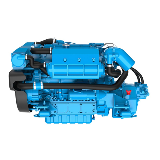
Page 37: S06 Components Engine Main Components Engine Views N4.115-N4.140
COMPONENTS S06 COMPONENTS ENGINE MAIN COMPONENTS Engine views N4.115-N4.140... - Page 38 COMPONENTS ENGINE MAIN COMPONENTS NOTE ! Minor engine details may not be exactly as shown. Some components may not be part of the engine ordered. Not binding pictures. COMPONENTS Alternator Alternator Belt Starter Fuses box Air filter Fuel filter Fuel feed pump Fuel injection pump Heat exchanger Coolant filler plug...
- Page 39 COMPONENTS ENGINES VIEWS N4.115-N4.140...
- Page 40 NOTES...
-
Page 41: S07 Start & Running
START & RUNNING S07 START & RUNNING BEFORE STARTING Engine installation Fuel system Raw water system Electrical system Check before starting STARTING THE ENGINE Cold weather operation Engine start Engine started Starting with booster batteries Engine reluctant to start Idling engine Normal engine operation Break in Power take off... -
Page 42: Before Starting
START & RUNNING BEFORE STARTING RAW WATER SYSTEM The raw water system allows to cool the engine coolant and the exhaust gas. ENGINE INSTALLATION Raw water is drawn into the heat exchanger by the engine See Installation manual raw water pump. The raw water is drained via the exhaust elbow, where it is mixed with exhaust gases. -
Page 43: Check Before Starting
Turn on the engine coolant heater for a minimum of 2 7. Check the coolant level, top up if necessary. hours before starting the engine. Additional information on cold weather operation is available from your Nanni 8. Check the mechanical control cables, lubricate as engine distributor or authorized servicing dealer. -
Page 44: Engine Start
START & RUNNING ENGINE START Type 4 panel with key: NOTE ! 1. Move the control lever to the neutral position. On Eco 4 Panel, only the oil pressure and battery charge NEUTRAL lamp light on. ASTERN AHEAD START STOP STARTING BEEP 2. - Page 45 START & RUNNING Type 4 panel without key: 1. Switch the key of the main panel to ignition (if 4. Press the Start button halfway (position 1/2) to start equipped). preheating. Hold the button for 10 to 20 seconds, depending on ambient temperature to preheat the 2.
-
Page 46: Engine Started
START & RUNNING ENGINE STARTED ENGINE RELUCTANT TO START If a water lift (water lock) muffler is installed on the exhaust line, excessive cranking could cause seawater NOTE ! to enter the cylinders and damage the engine. To start engine, reduce starting attempts to three and if not OK, undertake to do this: To insure adequate lubrication, operate engine at or below 1. -
Page 47: Normal Engine Operation
Any mechanical power taken from the engine from a PTO reduces the power delivered to the propeller. The use of a PTO should always be studied and approved by the R&D department of Nanni Industries S.A.S France. Contact your Nanni dealer for more informations. -
Page 48: Remote Control
Check the instruments and warning lamps after starting, prevents the engine from starting until the lever is in and regularly when cruising. neutral position. Consult the boat builder or your Nanni dealer if you are not sure about the operation of the remote control. -
Page 49: Cruising Speed
START & RUNNING CRUISING SPEED MANOEUVRING NOTE ! WARNING ! Always consider sailing conditions and load of the boat to Shifting at high speed can damage both the engine and set the cruising speed. the transmission and be dangerous for passengers. Operating the engine at wide open throttle should be avoided since it is both uncomfortable and uneconomical. -
Page 50: Engine And Sailing
START & RUNNING ENGINE AND SAILING CAUTION ! When under sail, it is possible to limit the resistance produced by the propeller of the engine. Sailing with the engine stopped and with the lever in neutral must not exceed 6 hours in a row. The propeller can drive the rotation of the shaft and damage the transmission. -
Page 51: After Running
START & RUNNING AFTER RUNNING AFTER STOPPING THE ENGINE STOPPING THE ENGINE CAUTION ! Even after the engine has stopped, some components CAUTION ! and fluids will remain hot and under pressure for several minutes. As far as possible, limit works on the engine immediately after stopping it. -
Page 52: Anchoring
START & RUNNING ANCHORING If the boat is not going to be used for some time but is being left in the water, the engine must be run to operating temperature at least once every 2 weeks. This prevents corrosion in the engine. When the boat is at anchor or in port for an extended period of time, vegetation may develop on the hull, the keel, the drive, the rudder, the propeller, etc. -
Page 53: S08 Maintenance
MAINTENANCE S08 MAINTENANCE ABOUT GENERALITIES CONTROL CABLES MAINTENANCE EXHAUST SYSTEM ENGINE MOUNTS CHECK TURBOCHARGER Turbo service AIR INTAKE Check the air filter box Cleaning the air filter FUEL SYSTEM Drain water in fuel prefilter Replacing the fuel filter Air bleeding LUBRICATION SYSTEM Oil level - adding engine oil Draining the engine oil... -
Page 54: About
CAUTION ! repair workshop nearby. We recommend to have all your works checked by a Nanni Clean the engine before any maintenance. Watch for any authorized workshop. -
Page 55: Control Cables
MAINTENANCE CONTROL CABLES The engine rpm and the gearbox shift command may be controlled by mechanical control cables connected to the control lever. Adjust the tightness of the cable as required. If any defect appears (rust, crack, etc.), the control cable must be replaced. -
Page 56: Maintenance
MAINTENANCE MAINTENANCE PERIODICITY Every Every Every Maintenance Daily 250 hours or 1 500 hours or 2 1000 hours or 30 days or COMPONENTS year ( years ( 4 years ( 25 hours ( Fuel Circuit Water in fuel - Pre-filter / Filter Draining Fuel filter ( Fuel injectors Lubrication Circuit... -
Page 57: Exhaust System
Follow manufacturer’s guidelines outside air. for mounting specifications. Front engine mounts (A) only are available from Nanni Diesel. Exhaust resistance must be as low as possible in order to prevent a decrease in power, however exhaust noise must be kept at an acceptable level. -
Page 58: Turbocharger
MAINTENANCE TURBOCHARGER TURBO SERVICE An engine turbocharger is designed to provide long years of trouble free service, which if required, can only be performed by a specialized workshop. In view to maintain CAUTION ! turbocharger performances for as long as possible, some basic rules must be followed. -
Page 59: Air Intake
MAINTENANCE AIR INTAKE CLEANING THE AIR FILTER Special tool For best results, order the NANNI fi lter cleaning kit: WARNING ! Number Description Illustration 970317077 Kit air filter cleaner EN, ESP, SUOMI Carry out these operations when the engine is stopped 970317078 Kit Air filter cleaner... -
Page 60: Fuel System
Any work on the fuel injection system must be carried 6. Bleed the fuel system (see in the following paragraphs). out by a authorized Nanni technician. Check regularly the condition of the components of the fuel system (hoses, 7. Start the engine and check for leaks. -
Page 61: Replacing The Fuel Filter
MAINTENANCE REPLACING THE FUEL FILTER AIR BLEEDING Bleeding the air in the fuel system might be required : • After a maintenance operation on the fuel system. NOTE ! • If the fuel tank has been emptied. • The engine has not been started for a long time. To ease up the air bleeding during fuel filter replacement, To bleed the fuel system fitted with the standard the filter assembly may be filled with some fuel, only if you... - Page 62 MAINTENANCE NOTE ! The mechanical fuel pump is functioning through the intermediate of an internal cam in the engine. Should this cam be in high position, the lever movement will be too small to operate. Turn the crankshaft a fraction to free the lever.
-
Page 63: Lubrication System
MAINTENANCE LUBRICATION SYSTEM OIL LEVEL - ADDING ENGINE OIL Check the engine and transmission oil level before starting the engine. The oil level should be within the range indicated on the dipstick, between the Mini and Maxi level. CAUTION ! How to check the oil level: 1. -
Page 64: Draining The Engine Oil
MAINTENANCE DRAINING THE ENGINE OIL CHANGING THE OIL FILTER Replace the oil filter every time the engine oil is drained. Principle of operation: 1. Start the engine and let it warm a few minutes to render oil more fluid to ease suction. 2. -
Page 65: Cooling System
• The RAW WATER CIRCUIT which cools the coolant via an heat exchange with raw water. Nanni engines are delivered as standard with an heat exchanger, in which the coolant is cooled by heat exchange with raw water taken from a sea cock. -
Page 66: Coolant Level
2. Stop the engine and remove the key from the panel. supplied from a general hardware store. 3. Unscrew the filler cap (in blue on below picture) on the A specific boiler kit is available from Nanni Industries. exchanger tank. Please contact your nearest Nanni representative for more 4. -
Page 67: Draining The Coolant Circuit
MAINTENANCE DRAINING THE COOLANT CIRCUIT To fill the coolant system: 1. Stop the engine and remove the key from the panel. 2. Put a container along with a hose under the drain plug (A) located at the bottom of the water cooling box to collect coolant. -
Page 68: Raw Water System
MAINTENANCE RAW WATER SYSTEM SIPHON BREAKER DANGER ! DANGER ! Close the sea cock before any operation on the siphon breaker. When the boat is on the water, it is possible than water can flow into the boat via components located below the waterline. -
Page 69: Extract The Raw Water Pump Impeller
MAINTENANCE EXTRACT THE RAW WATER PUMP IMPELLER To extract the impeller: 1. Stop the engine, remove the key from the panel and close the sea cock. CAUTION ! 2. Remove the top cover flange of the raw water pump (6 screws). 3. -
Page 70: Cleaning The Raw Water Filter
MAINTENANCE CLEANING THE RAW WATER FILTER RAW WATER SYSTEM - DRAINING The model of prefilter can vary according the boat as the raw water filter is an optional extra not in the scope of supply of the engine. These instructions are given as an WARNING ! example only. -
Page 71: Raw Water System - Cleaning
7. At this stage, the raw circuit is alleged to be cleaned up. If deposits and salt crystals are still present, consult your Nanni representative. Do not add up cleaners additives like caustic soda, as aluminium parts are prone to fast corrosion if harshly cleaned. -
Page 72: Electrical System
To charge two independent batteries with a single the alternator and the battery when the engine is running. alternator, an isolator is available as an option on most engines. Contact an authorized Nanni representative. WIRES AND CONNECTORS KEEP CLEAN THE BATTERY Check that electrical wires and connectors are dry and in good condition. -
Page 73: Disconnect The Starter Cables
Nominal Capacity (K20) Cold Test Icc good practice to check also the specific gravity with a hydrometer. Follow these indications : Unscrew completely the vent plugs and check level with a N4.115 150 (Min) -180 (Best) 900-1000 flashlight in each and every orifice. -
Page 74: Alternator Belt
MAINTENANCE ALTERNATOR BELT Check the belt tension: The engine alternator is driven by a belt through pulleys. These components must be in good order at all times in view for the alternator to provide electricity, among others, to the engine, to the battery, to the engine control panel. DANGER ! Depress the belt at point (A) and check for a deflection... -
Page 75: Fuses
first on your on in taking all usual precautions. If the fault is not resolved quickly, contact your nearest Nanni representative for repair. Fuse F4 If you are at open sea, try to locate the fault and to repair by yourself. -
Page 76: Miscellaneous
MAINTENANCE MISCELLANEOUS CAMSHAFT TIMING From camshaft down to crankshaft, timing is ordered through a gear system and is service free. -
Page 77: S09 Storage
9. Drain any water and contaminants from the fuel tank. of measures must be performed. All these operations should be carried out by a Nanni authorized workshop. 10. Fill totally the fuel tank. 11. Remove the air filter. Secure all air intake with clean clothes. -
Page 78: Restarting The Engine
STORAGE RESTARTING THE ENGINE BATTERY When storing the engine, adjust the battery electrolyte 1. Perform external cleaning of the engine and control level and store it in a dry place at room temperature. its condition. Recharge the battery as often as possible to extend its 2. -
Page 79: S10 Troubleshooting
CAUTION ! If the engine does not function properly, use the following chart to identify the cause. If the cause of trouble can not be found, contact to Nanni authorized workshop. NOTE ! Some components may not be part of the engine ordered. This list is not exhaustive and is only an assistance in case of emergencies. - Page 80 TROUBLESHOOTING 1. Lack of fuel 2. Air in fuel system 3. Fuel filter fouled or clogged 4. Fuel do not meet specified standard 5. Water/contaminants in fuel 6. Valve clearance is wrong * 7. Low compression * 8. Insufficient battery charge / Defective battery 9.
-
Page 81: Epa Warranty
This Emission Control System Warranty Statement applies solely to engines certifi ed to United States of America EPA 40 CFR 1042 and sold through Nanni Industries S.A.S - France network (named the "Company") that are instal- led in vessels fl agged or registered in the United States of America and associated waters (ie., Pacifi c & Carribean). - Page 82 NANNI MARINE DIESEL ENGINES WARRANTY LIMITATIONS ENGINE RESPONSABILITY As far as Nanni Industries S.A.S engines are EPA Nanni engines are assembled and tested in view to certified, it means that the Company guarantees that have minimum environmental impact as possible.
Need help?
Do you have a question about the N4.115 and is the answer not in the manual?
Questions and answers