Table of Contents
Advertisement
Advertisement
Table of Contents

Related Manuals for Buehler MiniMet 1000


Summary of Contents for Buehler MiniMet 1000
- Page 1 MiniMet™ 1000 MA691100_14.1 4/08/2013...
- Page 2 Continually improve our performance in all aspects of the business. About Buehler For over 75 years, Buehler has been a leading manufacturer of scientific instruments and supplies for use in materials analysis. Buehler products are used throughout the world in manufacturing facilities, quality laboratories and universities to analyze all types materials, including: •...
- Page 3 The information contained in this communication is intended only for the use of the individual or entity to which it is addressed and may contain information that is privileged, confidential and exempt from disclosure under applicable law. © 2009 – 2012 Buehler, a division of Illinois Tool Works Inc. All rights reserved. MA691100_14.1...
-
Page 4: Table Of Contents
Control Panel ............................5 Buttons ............................. 5 Running a Grinding-Polishing Cycle ....................... 7 Stopping a RUN CYCLE ........................7 MiniMet 1000 Polishing Bowl Preparation ....................8 Specimen Preparation ........................... 9 General Preparation Method ........................9 Maintenance ..............................10 Buehler Environmental Policy: ........................10 MiniMet 1000 Accessories .......................... -
Page 5: Minimet 1000 Grinder Polisher
This warranty covers all Buehler costs associated with the replacement of defective materials (e.g., parts and labor). If for any reason this unit must be returned to Buehler for warranty service, please contact Buehler Service at www.Buehler.com... -
Page 6: Safety Information
Improper operation, handling, or maintenance can result in equipment damage and personal injury. The MiniMet 1000 is designed for use in dry, indoor laboratory and workshop environments away from strong electromagnetic fields and with normal temperature ranges (41° F to 104° F / 5° C to 40° C) and non-condensing humidity ranges (30-90%). -
Page 7: Safety Terms
NOTICE indicates practices not related to personal injury. Unpacking The MiniMet 1000 has been carefully packaged to protect it during transit from the factory to your location. Carefully unpack and check the contents. If any components are missing or damaged, save the packing list and materials and advise the carrier and Buehler of the discrepancy. -
Page 8: Installation
Specification Plate. Activating the MiniMet 1000 To activate power to the MiniMet 1000, move the power switch on the back of the machine to the ON position. The power switch is also a circuit breaker that will provide protection for the machine in the event of an overload. -
Page 9: Operation
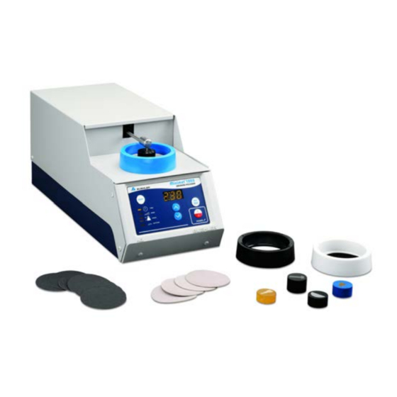
Control Panel To power on the MiniMet 1000, move the power switch on the back of the machine to the ON position and press the Power button on the control panel. Figure 1 MiniMet 1000 Grinder-Polisher Control Panel Buttons POWER .... - Page 10 (pounds or newtons) from 0 to 10 pounds, in 1 pound increments or 0 to 50 newtons, in 5 newton increments. When the MiniMet 1000 is first activated, the FORCE will be set to 0 (zero). Once a force value is entered, it will become the default force value until the power switch is flipped to the OFF position or the unit is unplugged.
-
Page 11: Running A Grinding-Polishing Cycle
Running a Grinding-Polishing Cycle When the RUN CYLCE is activated, the MiniMet 1000 will automatically display the remaining time in the LCD window and for the first 10 seconds of the cycle, the FORCE will be 50% of the initial FORCE value. -
Page 12: Minimet 1000 Polishing Bowl Preparation
MiniMet 1000 Polishing Bowl Preparation NOTICE To help avoid cross-contamination of abrasives, a bowl of a different color should be assigned to each abrasive step. 1. Apply a selected grinding paper or polishing cloth to a clean glass platen. Firmly attached the paper or cloth to the glass platen. -
Page 13: Specimen Preparation
Specimens are normally mounted in a manner to provide protection to critical edges and to provide a means of connection to the Load Arm. The MiniMet 1000 will accept standard format mounts in 1″ (25 mm), 1¼″ (32 mm), and 1½″ (38 mm) diameter. -
Page 14: Maintenance
Maintenance The MiniMet 1000 will continue to perform at optimum levels with proper care, daily cleaning, and general maintenance. • Wipe the exterior surface with a damp cloth daily. • Polishing bows should be cleaned at least once a week. -
Page 15: Minimet 1000 Accessories
MiniMet™ Accessories MiniMet 1000 Accessories Description Catalog Number Caged Sample Holder for 1″ (25 mm) or 1¼″ (32 mm) mounts ............69-1111 Caged Sample Holder for 1½″ (38 mm) mounts ................69-1112 Polishing Bowls. Set of 3, 1 each: Black, White, and Blue ..............69-1500 Polishing Bowls. - Page 16 MiniMet™ Drawings Note: Drawings and Parts List are subject to change without notice. Figure 6 MiniMet 1000 Assembly Diagram (1100900B Rev. A2) MA691100_14.1 [Original Instructions] 4/08/2013...
- Page 17 MiniMet™ Drawings Note: Drawings and Parts List are subject to change without notice. Figure 7 MiniMet 1000 Assembly Diagram Detail A (1100900C Rev. A5) MA691100_14.1 [Original Instructions] 4/08/2013...
- Page 18 MiniMet™ Drawings Note: Drawings and Parts List are subject to change without notice. R0612LW(3) Figure 8 MiniMet 1000 Assembly Diagram Detail B (1100900D Rev. A7) MA691100_14.1 [Original Instructions] 4/08/2013...
- Page 19 MiniMet™ Drawings Note: Drawings and Parts List are subject to change without notice. Figure 9 MiniMet 1000 Assembly Diagram Detail C (1100900E Rev. A5) MA691100_14.1 [Original Instructions] 4/08/2013...
- Page 20 MiniMet™ Drawings Note: Drawings and Parts List are subject to change without notice. Figure 10a MiniMet 1000 Assembly Diagram Detail D (1100900F Rev. A4) Figure 10b MiniMet 1000 Assembly Diagram Detail E (1100900F Rev. A4) MA691100_14.1 [Original Instructions] 4/08/2013...
- Page 21 MiniMet™ Drawings Note: Drawings and Parts List are subject to change without notice. Figure 11 MiniMet 1000 Assembly Diagram Detail F (1100900G Rev. A2) MA691100_14.1 [Original Instructions] 4/08/2013...
- Page 22 MiniMet™ Drawings Note: Drawings and Parts List are subject to change without notice. Figure 12 MiniMet 1000 Assembly Diagram Detail G (1100900H Rev. A3) MA691100_14.1 [Original Instructions] 4/08/2013...
- Page 23 MiniMet™ Drawings Note: Drawings and Parts List are subject to change without notice. Figure 13 MiniMet 1000 Electrical Diagram (1100900l Rev. A1) MA691100_14.1 [Original Instructions] 4/08/2013...
- Page 24 MiniMet™ Drawings Note: Drawings and Parts List are subject to change without notice. Figure 14 MiniMet 1000 Packaging Diagram (1100900J Rev. A3) MA691100_14.1 [Original Instructions] 4/08/2013...
- Page 25 CABINET, LOWER 1100S020 PLATE, MOTOR MOUNTING 1100S021 FACEPLATE, BOWL 1100S022 PLATE, DRIVE 1100S026 ARM, YOKE TO SPECIMEN HOLDER 1100S031#01 BEZEL, MINIMET 1000 1100S033 CABINET, UPPER 1100S034 SPRING, LEVER ARM 1100S037 SHAFT, GEAR DRIVE 1100S039 ADAPTER AND PIN ASSEMBLY 1100S049 SENSOR ASSEMBLY...
- Page 26 WASHER PLAIN M3, NYLON L691500 LABEL FOR 691500 BOWLS L691510 LABEL FOR 691510 PLATENS M6086 GROUND LABEL MN1KS002 GEARMOTOR, 12V MINIMET 1000 MN1KS004 SCREW, SET 6-32 X 1/2 SS MN1KS005 HUB, .312 SHAFT DIA R0603 NUT, 4-40 SS HEX R0605...
- Page 27 Parts List Part Number Description Note: Drawings and Parts List are subject to change without notice. R5102 LITHIUM GREASE gram R6110 4-1/16X1-1/4X11-13/16 BOX R6120 CARTON 3X3X1-1/4 R6183 SEPARATOR 3 IN MAX DIA 200# R6846 CARTON, 23.88X8.38X11.25 R6846A INSERT, RIGHT SIDE R6846B INSERT, LEFT SIDE R6846C...
- Page 28 Parts List Part Number Description Note: Drawings and Parts List are subject to change without notice. R9442 SCREW, 6-32 X 3/8 OV PAINT PLAT R9492 GROMMET, STRIP .032 X 3/8 0.08 R9502 O-RING, .424 ID X .103 C.S. R9809 FILTER, SNAP-IN RFI LINE R9810 TAPE, EMI/RFI SHIELDING 1.5 W 0.12...
- Page 29 Buehler, Asia-Pacific Web Site: http://www.buehler-asia.com 69570 Dardilly, France Fax: (852) 2307 0223 Tel: (04) 37 59 81 20 E-mail: info@buehler.com.hk Fax: (04) 37 59 81 29 Email: service.fr@buehler.com For all other service inquiries contact Buehler at www.buehler.com/locations/service.htm. MA691100_14.1 [Original Instructions] 4/08/2013...
- Page 30 Notes MA691100_14.1 [Original Instructions] 4/08/2013...
Need help?
Do you have a question about the MiniMet 1000 and is the answer not in the manual?
Questions and answers