
Related Manuals for Aqua Lung LPIS


Summary of Contents for Aqua Lung LPIS
- Page 1 LOW PRESSURE INFLATION SYSTEM (LPIS) DRY SUIT INFLATION SYSTEM (DSIS) USER'S MANUAL Rev. 1/16...
- Page 2 Aqua Lung America, Inc. ©2016 Aqua Lung International DSIS / LPIS User’s Manual PN 108609 You can contact a Technical Adviser via e-mail at: sreilly@aqualung.com grubin@aqualung.com jbutner@aqualung.com...
-
Page 3: Table Of Contents
General Precautions and Warnings ............4 Product Description ..................6 Preparation and Setup .................. 7 General Filling Procedures ................7 Filling Methods for DSIS / LPIS ..............9 Pre-Dive Inspection ..................19 Post-Dive Inspection .................. 21 Care and Maintenance ................21 Inspection and Service ................ -
Page 4: General Precautions And Warnings
WARNING: DO NOT apply any type of petroleum-based lubricant, such as household oil or motor oil to any part of the DSIS / LPIS. The DSIS / LPIS does not require any lubrication under normal circumstances, except that which is performed during inspection and service by a... - Page 5 -65°F / -53ºC dew point. Excess water vapor in the air can cause ice to form inside the DSIS / LPIS and interfere with the operation of the system at colder temperatures.
-
Page 6: Product Description
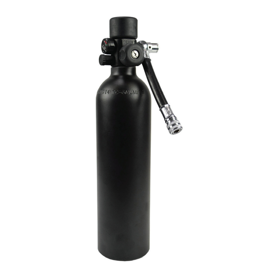
DSIS / LPIS Components (Fig. 1) • DSIS / LPIS piston first stage with integral fill port, dial pressure gauge, safety plug assembly and on / off knob. Black coated brass components are utilized on first stage for a low reflective signature. -
Page 7: Preparation And Setup
GENERAL FILLING PROCEDURES 1. Before attempting to fill the DSIS / LPIS, ensure that the fill adapter and first stage are completely dry – especially in the area surrounding the fill port. 2. The DSIS / LPIS is configured with a 3000 PSI (207 BAR) aluminum cylinder. - Page 8 If moisture is found to be present inside the fill port opening, this indicates that water may have entered the first stage and cylinder. DO NOT fill or attempt to use the DSIS / LPIS until it has received complete inspection and any required service by...
-
Page 9: Filling Methods For Dsis / Lpis
DO NOT attempt to loosen or remove any components on the first stage or hose assembly under any circumstances. Doing so could result in a dangerous malfunction of the DSIS / LPIS which could result in serious injury or death. - Page 10 DSIS / LPIS User's Manual CAUTION: Do not attempt to fill the DSIS / LPIS directly from a supply cylinder unless you have received the necessary training and authorization to do so. If done incorrectly, this procedure poses certain hazards which may cause severe injury or death.
- Page 11 7. Close the bleed valve screw on Figure 7 the fill adapter (Fig. 7). NOTE: The DSIS / LPIS will fill with the handwheel in the “OFF” position (red indicator ring visible). In this position the pressure gauge will not register PSI. This is not recommended.
- Page 12 10. When at least three minutes have elapsed and air can no longer be heard flowing from the supply cylinder into the DSIS / LPIS, completely open the supply cylinder valve. Verify the cylinder has been filled to 3000 PSI (34.5 BAR).
- Page 13 WARNING: DO NOT attempt to use the compressor fill adapter or fill the DSIS / LPIS from an airsource with a fill pressure greater than 3000 PSI (207 BAR). Doing so could cause a dangerous malfunction to the fill adapter or weaken the cylinder and safety...
- Page 14 (Fig. 10). Figure 10 NOTE: The DSIS / LPIS will fill with the valve handwheel in the “OFF” position (red indicator ring visible). In this position the pressure gauge will not register PSI. This is not recommended.
- Page 15 8. When at least three minutes have elapsed and air can no longer be heard flowing from the compressor fill hose into the DSIS / LPIS, completely open the compressor valve. Verify the cylinder has been filled to 3000 PSI (34.5 BAR).
- Page 16 DSIS / LPIS User's Manual Filling DSIS / LPIS with a HP Fill Adapter NOTE: The DSIS / LPIS system does not include a HP fill adapter. This adapter (PN 102865) may be purchased separately (Fig. 12). O-Ring Figure 12...
- Page 17 (Fig. 13). Figure 13 NOTE: The DSIS / LPIS will fill with the valve handwheel in the “OFF” position (red indicator ring visible). In this position the pressure gauge will not register PSI. This is not recommended.
- Page 18 6. When at least three minutes have elapsed and air can no longer be heard flowing from the compressor fill hose into the DSIS / LPIS, completely open the compressor valve. Verify the cylinder has been filled to 3000 PSI (34.5 BAR).
-
Page 19: Pre-Dive Inspection
PRE-DIVE INSPECTION Before each use, the DSIS / LPIS must be given a thorough visual inspection and functional test by a qualified technician. NEVER use a DSIS / LPIS which shows signs of damage, leakage or substandard performance. 1. Carefully inspect the medium pressure hose to ensure it is securely connected into its respective port on the first stage. - Page 20 PSI”, indicating a full cylinder (Fig. 18). Figure 18 CAUTION: Do not deplete the DSIS / LPIS of air during the pre- dive inspection. Doing so will drop the pressure below the “3000 PSI” and it will have to be topped off by maintenance personnel.
-
Page 21: Post-Dive Inspection
The following maintenance procedures should be performed routinely after each use of the equipment. 1. After each dive, the DSIS / LPIS must be cleaned, inspected and prepared for the next use or storage. 2. As soon as possible after diving, the DSIS / LPIS should be soaked thoroughly for at least one hour in warm (not over 120ºF /... - Page 22 6. Due to the possibility of fire and exposure to extreme heat, the DSIS / LPIS must be stored either completely full or completely empty. If the system is exposed to fire while partially filled, the cylinder wall may rupture before the internal pressure becomes great enough to burst the safety plug assembly.
-
Page 23: Inspection And Service
INSPECTION AND SERVICE 1. It cannot be assumed that the DSIS / LPIS is in good working order on the basis that it has received little use since it was last serviced. Remember that prolonged or improper storage can still result in internal corrosion and deterioration of o-ring seals and valve springs. -
Page 24: Technical Specifications
3000 PSI (207 BAR) 6 in (15 cm) - DSIS 9 in (23 cm) - DSIS Medium Pressure Hose Length 20 in (51 cm) - DSIS 33 in (84 cm) - LPIS First stage Hose Connection 360 Degree Swivel Regulator First Stage Piston Pressure Indicator Gauge 0–3000 PSI (0–207 BAR) -
Page 25: Dsis / Lpis Parts
DSIS / LPIS PARTS 820120 957004 O-ring O-ring 957004 O-ring 820312 O-ring PN 108325 Scuba Fill Adapter PN 100656 Compressor PN 102865 HP 3000 PSI (207 BAR) Fill Adapter Fill Adapter 3000 PSI (207 BAR) 4500 PSI (310 BAR) First Stage 360º... -
Page 26: Notes
DSIS / LPIS User's Manual NOTES... - Page 27 NOTES...
- Page 28 LOW PRESSURE INFLATION SYSTEM (LPIS) DRY SUIT INFLATION SYSTEM (DSIS) USER’S MANUAL 2340 Cousteau Court • Vista, CA 92081 Phone (760) 597-5000 • Fax (760) 597-4900 www.aqualung.com/militaryandprofessional ©2016 Aqua Lung International...
Need help?
Do you have a question about the LPIS and is the answer not in the manual?
Questions and answers