Table of Contents
Advertisement
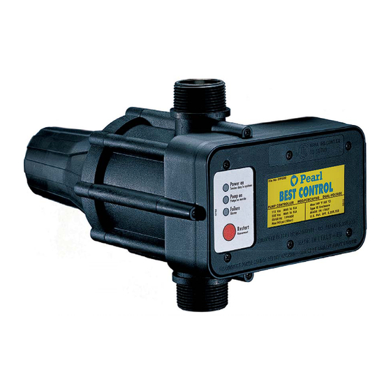
RESIDENTIAL PUMP CONTROLLER - MOD. PCBC16F16S
File No: E191502 Mod. MCA, MCB
File N N o: E191502 Mod. MCA, MCB
BEST CONTROL can be installed on surface and submersible pumps for residential, domestic irrigation and
booster systems.
- Avoids pressure and flow fluctuations.
- Eliminates pump pressure switch.
- Built-in pressure and flow switch.
-
B
i u
- t l
n i
c
h
e
k c
v
a
v l
. e
-
B
i u
- t l
n i
r d
- y
u r
n
p
o r
e t
- Dual voltage 115 / 230 VAC.
READ THESE INSTRUCTIONS CAREFULLY BEFORE INSTALLATION
INSTALLER - PLEASE LEAVE THIS MANUAL WITH THE UNIT OR GIVE TO END USER.
OWNER'S MANUAL
115 / 230 VAC DUAL VOLTAGE UNIT
FEATURES & BENEFITS
c
o i t
. n
- All inoxidable components.
- Assists in absorbing water hammer.
- Can be used with or without pressure tank.
-
S
m i
p
e l
n i
t s
l l a
t a
o i
n
s
a
v
-
N
o
a
d
u j
t s
m
e
t n
r o
m
a
n i
™
e
s
s
p
c a
e
a
n
d
t
m i
. e
e t
n
a
n
c
e
e r
q
i u
e r
. d
Advertisement
Table of Contents

Related Manuals for Pearl PCBC16F16S

Summary of Contents for Pearl PCBC16F16S
- Page 1 ™ RESIDENTIAL PUMP CONTROLLER - MOD. PCBC16F16S OWNER’S MANUAL 115 / 230 VAC DUAL VOLTAGE UNIT File No: E191502 Mod. MCA, MCB File N N o: E191502 Mod. MCA, MCB FEATURES & BENEFITS BEST CONTROL can be installed on surface and submersible pumps for residential, domestic irrigation and booster systems.
-
Page 2: Table Of Contents
TABLE OF CONTENTS Page Precautions and warnings…..…………………………………………………………….……….. 2 Technical specifications……………………………………………………………………………. 3 Operation……..……………………………………………………………………………………... 3 Troubleshooting…………………………………………………………………………….………. 3 Maintenance and spare parts……………………………………………………………….…….. 3 Hydraulic connection to the system……………………………………………………….……... 4 Conduit connections………………………………………………………………………….….…. 4 Typical BEST CONTROL installation on surface and submersible pumps…………...….…. 5 BEST CONTROL installation guidelines and warnings…...…………………………….…….. 6 When to use pressure tank…………………………….……………………………………..……... -
Page 3: Precautions And Warnings
PLEASE READ BEFORE PROCEEDING WITH INSTALLATION FAILURE TO READ AND CONSIDER SAFETY INSTRUCTIONS IN THIS MANUAL OR ON BEST CONTROL MAY RESULT IN PERSONAL INJURY OR SERIOUS DAMAGE TO PIPING OR FIXTURES ! This is the safety alert. When you see this symbol in this manual, look for one of the following signal words and be alert to the potential for personal injury. -
Page 4: Technical Specifications
TECHNICAL SPECIFICATIONS - Single phase power-supply voltage 115 / 230 VAC l l u l l u F ˚ C ˚ t e l ” MPT o i t ½ ” FPT On request BEST CONTROL is available with inlet and outlet connections 1 ¼... -
Page 5: Hydraulic Connection To The System
HYDRAULIC CONNECTION TO THE SYSTEM Always install BEST CONTROL with flow arrows in the vertical position. Electronic box must be level. Do not install any tee or tap between pump and BEST CONTROL unit. Prepare all threads with Teflon tape only. Do not over thighten water connections, especially when installing with metal couplings. -
Page 6: Typical Best Control Installation On Surface And Submersible Pumps
- 5 -... -
Page 7: Best Control Installation Guidelines And Warnings
- 6 -... -
Page 8: Calibration
CALIBRATION Both BEST CONTROL models 1 1/4” and 1” can be provided with three different factory preset cut -in pressures. Use the appropriate guidelines below for the specific model. A - BEST CONTROL preset cut-in pressure 22 psi model: • Max pressure generated by the pump must be at least 45 psi. -
Page 9: Pressure Loss - Bypass Application
PRESSURE LOSS - BYPASS APPLICATION Pressure Loss Chart Flow rate Best control 1 ¼’’ psi loss 12.5 Best control 1’’ psi loss Use BEST CONTROL 1” in a bypass when friction loss is excessive. Gauge 1’’ 1’’ Gate valve BEST CONTROL 1” Spring check valve System pipe System pipe... -
Page 10: Electrical Connections
ELECTRICAL CONNECTIONS OBSERVE WARNINGS AND PRECAUTIONS LISTED AT THE FRONT OF THIS MANUAL. Electrical connections should made by a qualified professional in compliance with applicable local codes and National Electric Code. ALWAYS SHUT OFF POWER FOR INSTALLATION OR SERVICE. Check voltage of pump and supply to determine pump motor FLA and follow applicable BEST CONTROL wiring diagram. -
Page 11: Installation Wiring Diagram - 230Vac 2-Wire Pumps Up To 20 Fla
INSTALLATION WIRING DIAGRAM - 230VAC 2-WIRE PUMPS UP TO 20 FLA INSTALLATION WIRING DIAGRAM - 230VAC 3-WIRE PUMPS UP TO 20 FLA - 10 -... -
Page 12: When To Use Contactors
WHEN TO USE CONTACTORS Use a contactor when: On 115V installations pump motor full load amps exceed 16 FLA. On 230V installations pump motor full load amps exceed 20 FLA. On all three-phase applications. Remember, match coil voltage on contactor with BEST CONTROL voltage. Either 115V or 230V coils may be used. -
Page 13: Installation Wiring Diagram - 208 Vac Or 230 Vac Three Phase 3-Wire Pumps
- 12 -... -
Page 14: Installation Wiring Diagram - 230 Vac 3-Wire Pumps Exceedings 20 Fla
INSTALLATION WIRING DIAGRAM - 230VAC 3-WIRE PUMPS EXCEEDING 20 FLA OVERALL DIMENSIONS - 13 -... -
Page 15: Electronic Box Replacement
ELECTRONIC BOX REPLACEMENT Before removing the electronic box ensure that power unit is off and unit is depressurized. 1) Remove the box cover and disconnect the electrical wires. 2) Take off the box by removing the three screws attaching the electronic box to the unit body.
Need help?
Do you have a question about the PCBC16F16S and is the answer not in the manual?
Questions and answers