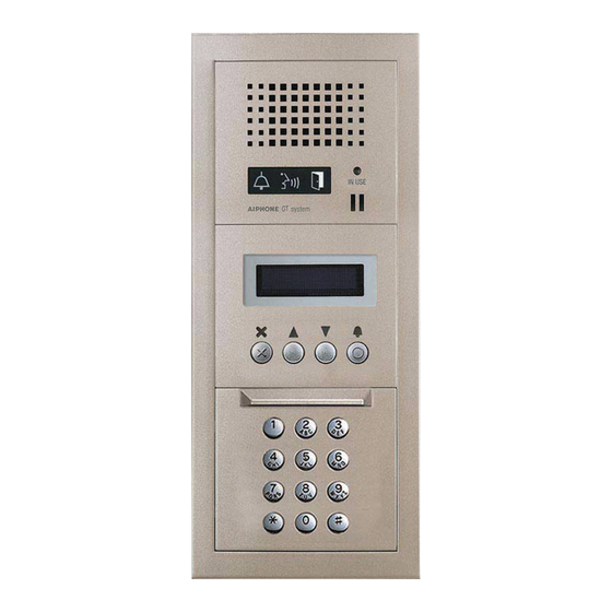
Aiphone GT System Quick Start Installation Manual
Standard & expanded system
Hide thumbs
Also See for GT System:
- Operation manual (25 pages) ,
- Installation manual (60 pages) ,
- User manual (14 pages)
Advertisement
Standard & Expanded System
Quick Start Installation Guide
ATTENTION:
This is an abbreviated Installation Manual, addressing wiring and programming of the GT Series. The
complete GT Series Installation Manual is located on the CD supplied with the GT-BC Bus Control
Unit. Access the PDF fi le from the CD and print the entire manual if a hard copy is needed. If installing a digital
entry system, the program for loading names and numbers for each residence is also located on the CD.
GT SYSTEM
Advertisement
Table of Contents

Summary of Contents for Aiphone GT System
- Page 1 GT SYSTEM Standard & Expanded System Quick Start Installation Guide ATTENTION: This is an abbreviated Installation Manual, addressing wiring and programming of the GT Series. The complete GT Series Installation Manual is located on the CD supplied with the GT-BC Bus Control Unit.
-
Page 2: System Wiring
Power Transformer (Use proper power for the Strike or Mag Lock being used). *Distribution Point: R1 R2 R1 R2 NOT provided by Aiphone Door except for Europe. This Strike Lock can be any device that parallels or commons the R1 / R2 connection. - Page 3 PS24 A1 A2 A1 A2 A1 A2 A1 A2 A1 A2 GT-VBC GT-BC *Distribution Point: NOT provided by Aiphone except for Europe. This can be any R1 R2 A1 A2 device that parallels or commons the R1 / R2 connection. (Terminal strip, punch down block, wire nuts, etc.)
-
Page 4: Expanded System
Connection GT-BC. for audio entrance modules 9-16 GT-MK GT-MK *Distribution Point: NOT provided by Aiphone except for Europe. This can PS24 be any device that parallels GT-BCX or commons the R1 / R2 connection. (Terminal strip, PS24 punch down block, wire : Audio line nuts, etc.) -
Page 5: Dip Switch Settings
DIP SWITCH SETTINGS: ENTRANCE STATION (REQUIRED) Entrance ID Setting: Use SW2 on the GT-DA(-L) module or SW1 on the GT-DM(V)A entrance station to set the ID settings for each entry panel. Only switches 2, 3, & 4 are used for this setting. GT-DA-L GT-DMVA GT-DA... - Page 6 XP, Windows Vista , Windows 7, or Windows ® ® ® ® Open GT software, click GT System Mode . Step 2: Step 3: Select Resident tab. Step 4: Enter a Room # and Name (if desired) for each resident. Step 5: Connect the USB cable to the PC and to the GT device being programmed.
- Page 7 PROGRAMMING: ADDRESSING RESIDENCES VIA HAND-SHAKE METHOD (continued) GT Entrance Station Addressing Step 1: Remove front panel from entrance station. Step 2: To enter programming, use a small screwdriver to push and release button under the rubber cap on front of speaker module (GT-DA(-L)). The amber LED will begin blinking, then remain lit. Once lit, the entrance station is in programming mode.
- Page 8 ® 7, or Windows ® B252 (Refer to page 6 for COM Port selection steps.) Step 4: Open the GT software, select [GT System Mode]. B253 Select the Resident tab. Step 5: B254 Step 6: Enter a Room # and Name for each residence to be programmed.


Need help?
Do you have a question about the GT System and is the answer not in the manual?
Questions and answers
Could you please provide me with installers in Brisbane, qld - I am having problems with my unit being the only one not working and handset has been replaced. The body corporate has suggested that maybe it wasn’t installed properly in the first instance.
Available Aiphone system installers in Brisbane, QLD include:
1. KGB Security – They offer intercom system installation, service, and repairs in Brisbane.
2. DLG Electrical – They are experienced installers of the Aiphone JO Series and provide retrofit installation services.
This answer is automatically generated