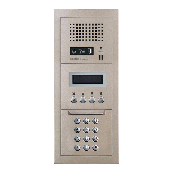
Aiphone GT System Quick Start Installation Manual
Standard & expanded system
Hide thumbs
Also See for GT System:
- Operation manual (25 pages) ,
- Installation manual (60 pages) ,
- User manual (14 pages)
Advertisement
Quick Links
Standard & Expanded System
Quick Start Installation Guide
ATTENTION:
This is an abbreviated Installation Manual, addressing wiring and programming of the GT Series. The
complete GT Series Installation Manual is located on the CD supplied with the GT-BC Bus Control
Unit. Access the PDF fi le from the CD and print the entire manual if a hard copy is needed. If installing a digital
entry system, the program for loading names and numbers for each residence is also located on the CD.
GT SYSTEM
Advertisement

Summary of Contents for Aiphone GT System
- Page 1 GT SYSTEM Standard & Expanded System Quick Start Installation Guide ATTENTION: This is an abbreviated Installation Manual, addressing wiring and programming of the GT Series. The complete GT Series Installation Manual is located on the CD supplied with the GT-BC Bus Control Unit.
-
Page 2: System Wiring
Power Transformer (Use proper power for the Strike or Mag Lock being used). *Distribution Point: R1 R2 R1 R2 NOT provided by Aiphone Door except for Europe. This Strike Lock can be any device that parallels or commons the R1 / R2 connection. - Page 3 PS24 A1 A2 A1 A2 A1 A2 A1 A2 A1 A2 GT-VBC GT-BC *Distribution Point: NOT provided by Aiphone except for Europe. This can be any R1 R2 A1 A2 device that parallels or commons the R1 / R2 connection. (Terminal strip, punch down block, wire nuts, etc.)
-
Page 4: Expanded System
Connection GT-BC. for audio entrance modules 9-16 GT-MK GT-MK *Distribution Point: NOT provided by Aiphone except for Europe. This can PS24 be any device that parallels GT-BCX or commons the R1 / R2 connection. (Terminal strip, PS24 punch down block, wire : Audio line nuts, etc.) -
Page 5: Dip Switch Settings
DIP SWITCH SETTINGS: ENTRANCE STATION (REQUIRED) Entrance ID Setting: Use SW2 on the GT-DA(-L) module or SW1 on the GT-DM(V)A entrance station to set the ID settings for each entry panel. Only switches 2, 3, & 4 are used for this setting. GT-DA-L GT-DMVA GT-DA... - Page 6 XP, Windows Vista , Windows 7, or Windows ® ® ® ® Open GT software, click GT System Mode . Step 2: Step 3: Select Resident tab. Step 4: Enter a Room # and Name (if desired) for each resident. Step 5: Connect the USB cable to the PC and to the GT device being programmed.
- Page 7 PROGRAMMING: ADDRESSING RESIDENCES VIA HAND-SHAKE METHOD (continued) GT Entrance Station Addressing Step 1: Remove front panel from entrance station. Step 2: To enter programming, use a small screwdriver to push and release button under the rubber cap on front of speaker module (GT-DA(-L)). The amber LED will begin blinking, then remain lit. Once lit, the entrance station is in programming mode.
- Page 8 ® 7, or Windows ® B252 (Refer to page 6 for COM Port selection steps.) Step 4: Open the GT software, select [GT System Mode]. B253 Select the Resident tab. Step 5: B254 Step 6: Enter a Room # and Name for each residence to be programmed.


