Sign In
Upload
Download
Table of Contents
Contents
Add to my manuals
Delete from my manuals
Share
URL of this page:
HTML Link:
Bookmark this page
Add
Manual will be automatically added to "My Manuals"
Print this page
×
Bookmark added
×
Added to my manuals
Manuals
Brands
Thermo Scientific Manuals
Freezer
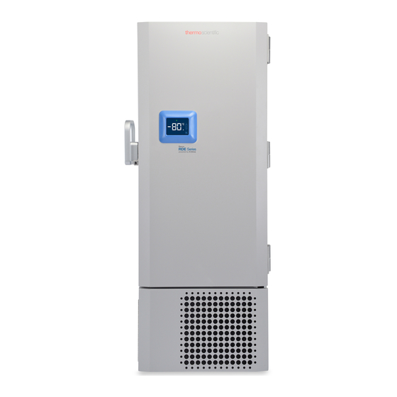
Revco RDE Series
Installation and operation manual
Thermo Scientific Revco RDE Series Installation And Operation Manual
Ultra-low temperature freezers
Hide thumbs
1
2
Table Of Contents
3
4
5
6
7
8
9
10
11
12
13
14
15
16
17
18
19
20
21
22
23
24
25
26
27
28
29
30
page
of
30
Go
/
30
Contents
Table of Contents
Troubleshooting
Bookmarks
Table of Contents
Table of Contents
Models
Safety Considerations
Unpacking
Packing List
General Recommendations
Temperature Monitoring
General Usage
Initial Loading
Battery Door Opening / Closing
Operating Standards
Electrical Specifications
Installation
Location
Leveling
Backup System (Optional)
Super Insulated Cabinet Construction
Door Operation
Pressure Equalization Port
Installing the Remote Alarm Connector
Intended Use
Operation
Initial Start up
Operation Overview
Display
Settings
Power down
Backup System (Optional)
CO2 and LN2 Precautions
Installation
Start up
Operation
Chart Recorders (Optional)
Set up and Operation
Changing Chart Paper
Calibration Adjustment
Maintenance
Cleaning the Condenser
Cleaning the Condenser Filter
Gasket Maintenance
Defrosting the Freezer
Battery Maintenance
Maintenance Schedule
Troubleshooting Guide
Error Codes
Warranty
Warranty (International)
Appendix A: Alarm Summary
Contact Information
Advertisement
Quick Links
1
Models
2
Temperature Monitoring
3
Display
4
Troubleshooting Guide
5
Error Codes
Download this manual
Ultra-Low Temperature Freezers
Revco
TM
Series, HERAfreeze
Thermo Scientific
Installation and Operation
329712H02 • Revision A • March 2019
RDE Series, Forma
HDE Series and
TM
TDE Series
TM
FDE
TM
Table of
Contents
Previous
Page
Next
Page
1
2
3
4
5
Advertisement
Table of Contents
Need help?
Do you have a question about the Revco RDE Series and is the answer not in the manual?
Ask a question
Questions and answers
Related Manuals for Thermo Scientific Revco RDE Series
Freezer Thermo Scientific TDE Series Manual
Ultra-low temperature freezers (46 pages)
Freezer Thermo Scientific Revco Slimline Installation And Operation Manual
Thermo scientific revco slimline value ultra-low temperature si freezers (13 pages)
Freezer Thermo Scientific Ultima II Installation And Operation Manual
Thermo scientific revco cryogenic storage freezers (15 pages)
Freezer Thermo Scientific Fisher Scientific 900 Series Operating And Maintenance Manual
Forma -86c ult freezer (88 pages)
Freezer Thermo Scientific TSG Series Installation And Operation Manual
General purpose freezers (60 pages)
Freezer Thermo Scientific TSX Series Installation And Operation Manual
-20 c laboratory and enzyme freezers (48 pages)
Freezer Thermo Scientific TSX Series Installation And Operation Manual
Ultra low temperature freezers (62 pages)
Freezer Thermo Scientific TSX Series Installation And Operation Manual
Ultra low temperature freezers (81 pages)
Freezer Thermo Scientific Isotemp IUE 86L Series Installation And Operation Manual
-86c freezers (29 pages)
Freezer Thermo Scientific HERAfreeze HFU Series Operating And Maintenance Manual
-40c and -86c ult chest freezer (110 pages)
Freezer Thermo Scientific ULT-10140-9-D Installation And Operation Manual
Cryogenic storage freezers (32 pages)
Freezer Thermo Scientific TSX Series Installation And Operation Manual
Ultra low temperature freezers (76 pages)
Freezer Thermo Scientific Jewett CTF306 Installation And Operation Manual
(16 pages)
Freezer Thermo Scientific TSX Core Installation And Operation Manual
Ultra low temperature freezers (56 pages)
Freezer Thermo Scientific CryoExtra CE8100 Series Operating And Maintenance Manual
Liquid nitrogen storage systems (133 pages)
Freezer Thermo Scientific Forma 900 Series Operating And Maintenance Manual
86c ult upright freezer (82 pages)
This manual is also suitable for:
Herafreeze hde series
Forma fde series
Forma fde***86l series
Herafreeze hde***86l series
Thermo scientific tde***86l series
Thermo scientific tde series
...
Show all
Revco rde***86l
Table of Contents
Save PDF
Print
Rename the bookmark
Delete bookmark?
Delete from my manuals?
Login
Sign In
OR
Sign in with Facebook
Sign in with Google
Upload manual
Upload from disk
Upload from URL


Need help?
Do you have a question about the Revco RDE Series and is the answer not in the manual?
Questions and answers