Table of Contents
Advertisement
Quick Links
Notes: Please refer to the Original Service Manual for :
CD Mechanism Unit, Order No. PSG1303059AE
Speaker system SB-PMX100EGK, Order No. PSG1505005CE
TABLE OF CONTENTS
1 Safety Precautions----------------------------------------------- 3
1.1. General Guidelines---------------------------------------- 3
1.2. Before Repair and Adjustment ------------------------- 3
1.3. Protection Circuitry ---------------------------------------- 4
1.4. Caution For Fuse Replacement------------------------ 4
1.5. Safety Part Information----------------------------------- 4
2 Warning -------------------------------------------------------------- 5
to Electrostatically Sensitive (ES) Devices---------- 5
2.2. Precaution of Laser Diode------------------------------- 6
2.4. Handling Precaution for Traverse Unit --------------- 8
3 Service Navigation ----------------------------------------------- 9
3.1. Service Information --------------------------------------- 9
3.2. Software / Firmware Update ---------------------------- 9
4 Specifications ----------------------------------------------------10
Model No.
Product Color: (S)...Silver Type
PAGE
5 Location of Controls and Components------------------ 12
Operations ------------------------------------------------- 12
6 Service Mode ----------------------------------------------------- 13
6.1. Service Mode Table ------------------------------------- 13
6.2. Service Mode Error Code ------------------------------ 14
6.3. Doctor Mode----------------------------------------------- 15
6.4. Sales Demonstration Lock Function Mode -------- 18
7 Troubleshooting Guide --------------------------------------- 19
8 Disassembly and Assembly Instructions--------------- 25
8.1. Disassembly flow chart --------------------------------- 26
8.2. Type of screws-------------------------------------------- 26
8.3. Main Parts Location Diagram ------------------------- 27
8.4. Disassembly of Top Cabinet--------------------------- 28
8.5. Disassembly of ALLPLAY Module Block ----------- 29
8.6. Disassembly of Front Panel Unit --------------------- 30
© Panasonic Corporation 2017. All rights reserved.
Unauthorized copying and distribution is a violation of
law.
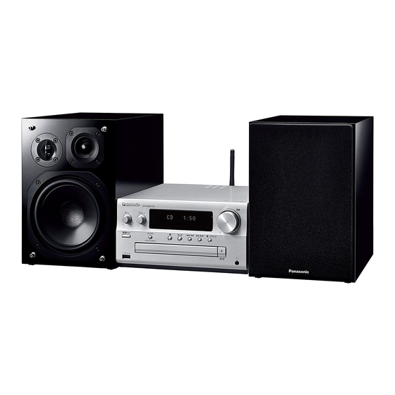
CD Stereo System
SA-PMX150EG
SA-PMX150PC
SA-PMX152EG
PSG1703007CE
A6
PAGE
Advertisement
Table of Contents


Need help?
Do you have a question about the SA-PMX152EG and is the answer not in the manual?
Questions and answers