Table of Contents
Advertisement
Quick Links
Notes: Please refer to the Original Service Manual for :
CD Mechanism Unit (BRS12C), Order No. PSG1303059AE
Speaker system SB-PMX70EG-K, Order No. PSG1502006CE
TABLE OF CONTENTS
1 Safety Precautions----------------------------------------------- 3
1.1. General Guidelines---------------------------------------- 3
1.2. Before Repair and Adjustment ------------------------- 4
1.3. Protection Circuitry ---------------------------------------- 4
1.4. Caution For Fuse Replacement------------------------ 4
1.5. Safety Part Information----------------------------------- 4
2 Warning -------------------------------------------------------------- 5
to Electrostatically Sensitive (ES) Devices---------- 5
2.2. Precaution of Laser Diode------------------------------- 6
Model No.
Product Color: (S)...Silver Type
PAGE
2.4. Handling Precaution for Traverse Unit----------------8
3 Service Navigation --------------------------------------------- 10
3.1. Service Information -------------------------------------- 10
4 Specifications ---------------------------------------------------- 11
5 Location of Controls and Components------------------ 12
Operations ------------------------------------------------- 12
6 Service Mode ----------------------------------------------------- 13
6.1. Service Mode Table ------------------------------------- 13
© Panasonic Corporation 2015. All rights reserved.
Unauthorized copying and distribution is a violation of
law.
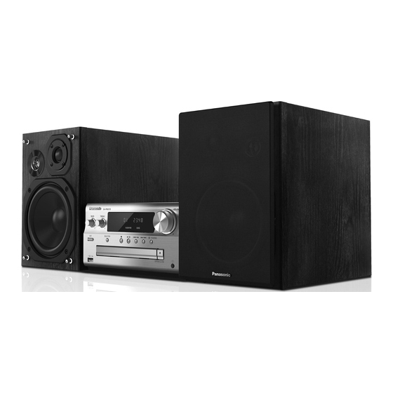
CD Stereo System
SA-PMX70EG
(K)... Black Type
PSG1502005CE
PAGE
Advertisement
Table of Contents

Related Manuals for Panasonic SA-PMX70EG


Summary of Contents for Panasonic SA-PMX70EG
-
Page 1: Table Of Contents
Operations ------------------------------------------------- 12 to Electrostatically Sensitive (ES) Devices---------- 5 6 Service Mode ----------------------------------------------------- 13 2.2. Precaution of Laser Diode------------------------------- 6 6.1. Service Mode Table ------------------------------------- 13 © Panasonic Corporation 2015. All rights reserved. Unauthorized copying and distribution is a violation of law. - Page 2 6.2. Service Mode Error Code ------------------------------ 14 6.3. Doctor Mode----------------------------------------------- 15 6.4. Sales Demonstration Lock Function Mode -------- 18 7 Troubleshooting Guide---------------------------------------- 19 7.1. No Power--------------------------------------------------- 19 7.2. No Sound to speaker unit (at times or all the times)-------------------------------------------------------- 19 7.3.
-
Page 3: Safety Precautions
1 Safety Precautions 1.1. General Guidelines 1. IMPORTANT SAFETY NOTICE There are special components used in this equipment which are important for safety. These parts are marked by in the Schematic Diagrams, Circuit Board Layout, Exploded Views and Replacement Parts List. It is essential that these critical parts should be replaced with manufacturer’s specified parts to prevent X-RADIATION, shock, fire, or other hazards. -
Page 4: Before Repair And Adjustment
1.2. Before Repair and Adjustment Disconnect AC power & discharge AC Capacitors (C5700, C5701, C5702, C5705 and C5706) through a 10W, 1W resistor to ground. Caution : DO NOT SHORT-CIRCUIT DIRECTLY (with a screwdriver blade, for instance), as this may destroy solid state devices. After repairs are completed, restore power gradually using a variac, to avoid overcurrent. -
Page 5: Warning
2 Warning 2.1. Prevention of Electrostatic Discharge (ESD) to Electrostatically Sensi- tive (ES) Devices Some semiconductor (solid state) devices can be damaged easily by static electricity. Such components commonly are called Elec- trostatically Sensitive (ES) Devices. The following techniques should be used to help reduce the incidence of component damage caused by electrostatic discharge (ESD). -
Page 6: Precaution Of Laser Diode
2.2. Precaution of Laser Diode CAUTION! THIS PRODUCT UTILIZES A LASER. USE OF CONTROLS OR ADJUSTMENTS OR PERFORMANCE OF PROCEDURES OTHER THAN THOSE SPECIFIED HEREIN MAY RESULT IN HAZARDOUS RADIATION EXPOSURE. Caution: This product utilizes a laser diode with the unit turned "on", invisible laser radiation is emitted from the pickup lens. Wavelength: 790 nm (CD) Maximum output radiation power from pickup: 100 μW/VDE Laser radiation from the pickup unit is safety level, but be sure the followings:... -
Page 7: Service Caution Based On Legal Restrictions
2.3. Service caution based on Legal restrictions 2.3.1. General description about Lead Free Solder (PbF) The lead free solder has been used in the mounting process of all electrical components on the printed circuit boards used for this equipment in considering the globally environmental conservation. The normal solder is the alloy of tin (Sn) and lead (Pb). -
Page 8: Handling Precaution For Traverse Unit
2.4. Handling Precaution for Traverse Unit The laser diode in the optical pickup unit may break down due to static electricity of clothes or human body. Special care must be taken avoid caution to electrostatic breakdown when servicing and handling the laser diode in the Traverse Unit. Cautions to Be Taken in Handling the Optical Pickup Unit 2.4.1. -
Page 9: Grounding For Electrostatic Breakdown Prevention
Grounding for electrostatic breakdown prevention 2.4.2. Some devices such as the CD player use the optical pickup (laser diode) and the optical pickup will be damaged by static electricity in the working environment. Proceed servicing works under the working environment where grounding works is completed. 2.4.2.1. -
Page 10: Service Navigation
3 Service Navigation 3.1. Service Information This service manual contains technical information which will allow service personnel’s to understand and service this model. Please place orders using the parts list and not the drawing reference numbers. If the circuit is changed or modified, this information will be followed by supplement service manual to be filed with original service manual. -
Page 11: Specifications
1152 to 4096. RMS Output Power *5: Support profile AAC-LC only. 60 W per channel (3 Ω), 1 kHz, Front Ch (both ch driven) System : SC-PMX70EG-K Music center: SA-PMX70EG-K 10% THD Speaker: SB-PMX70EG-K Total RMS power 120 W System : SC-PMX70EG-S... -
Page 12: Location Of Controls And Components
5 Location of Controls and Components 5.1. Main Unit & Remote Control Key Button Operations... -
Page 13: Service Mode
6 Service Mode This unit is equipped with features of self diagnostic & doctor mode setting for checking the functions & reliability. 6.1. Service Mode Table Item FL display Key operation Mode name Description Step 1 : Select CD mode Service Mode To enter into Service Mode (Ensure no disc is inserted). -
Page 14: Service Mode Error Code
6.2. Service Mode Error Code 6.2.1. CD Mechanism Error Code Table Error Code Diagnostic Contents Description of error of error Automatic FL Display Remarks During normal operation, if CD H15 CD Open Abnormal Press [ ] on main unit for “POS_SW_R (OPEN_SW)”... -
Page 15: Doctor Mode
6.3. Doctor Mode 6.3.1. Doctor Mode Table 1 Item Key Operation FL Display Front Key Mode Name Description Doctor Mode To enter into Doctor Mode for (Display 1) In any mode: checking of various items and Press button on main unit follow by displaying EEPROM check sum [4] &... -
Page 16: Doctor Mode Table
6.3.2. Doctor Mode Table 2 Item Key Operation FL Display Front Key Mode Name Description CD Combination To check the open/close In Doctor Mode: Test operation & inner outer disc Press [ ] follow by [1] & then [5] access operation. button on the remote control. - Page 17 6.3.3. Doctor Mode Table 3 Item Key Operation FL Display Front Key Mode Name Description Region Check Checking for model no and In Doctor Mode: Region Press [ ] follow by [1] & then [6] button on the remote control. To cancel, press [0] button on remote The [NO DISC] display will appear after 2s.
-
Page 18: Sales Demonstration Lock Function Mode
6.4. Sales Demonstration Lock Function Mode 6.4.1. Enter into Sales Demo Mode Here is the procedures to enter into Sales Demo Mode. Step 1 : Turn on the unit. Step 2 : Press and hold [OPEN/CLOSE] and [SELECTOR] keys for 5 secs. Step 3 : The display will show entering into the mode. -
Page 19: Troubleshooting Guide
7 Troubleshooting Guide 7.1. No Power No power during power-on of the unit Table1 SMPS H2015 -MAIN CN1100) Pin No. Voltage Value Confirmation if AC Power from SMPS P.C.B. to Main P.C.B. Is AC Power present at the AC Inlet (P5701) ? Check AC Cord and AC Inlet &... -
Page 20: List Of Possible Cause Of Failure By Function
7.3. List of possible cause of failure by function Table6 The P.C.B. that could be speculated as the cause of failure by a function Item No. Function P.C.B./Module Bluetooth Bluetooth P.C.B./Main P.C.B. Bluetooth P.C.B./NFC P.C.B./Main P.C.B. USB P.C.B.(Components)/Main P.C.B. CD Interface P.C.B.(Components)/Main P.C.B. Tuner Tuner P.C.B.(Components)/Main P.C.B. -
Page 21: Disassembly And Assembly Instructions
8 Disassembly and Assembly Instructions Caution Note: • This section describes the disassembly and/or assembly procedures for all major printed circuit boards & main compo- nents for the unit. (You may refer to the section of “Main components and P.C.B Locations” as described in this service manual) •... -
Page 22: Disassembly Flow Chart
8.1. Disassembly flow chart The following chart is the procedure for disassembling the casing and inside parts for internal inspection when carrying out the ser- vicing. To assemble the unit, reverse the steps shown in the chart below. 8.2. Type of screws... -
Page 23: Main Parts Location Diagram
8.3. Main Parts Location Diagram... -
Page 24: Disassembly Of Top Cabinet
8.4. Disassembly of Top Cabinet Step 3 : Lift up Top Cabinet as arrow shown. Step 4 : Remove Top Cabinet. Step 1 : Remove 2 screws. Step 2 : Remove 3 screws. -
Page 25: Disassembly Of Front Panel Unit
8.5. Disassembly of Front Panel Step 5 : Release tabs on both sides of Front Panel Unit. Step 6 : Press to release catch. Unit Step 7 : Remove Front Panel Unit. • Refer to “Disassembly of Top Cabinet” Step 1 : Remove screw and detach ground wire. Step 2 : Detach 7P wire at connector (CN6000) on Main P.C.B.. -
Page 26: Disassembly Of Panel P.c.b. Unit
8.6. Disassembly of Panel P.C.B. 8.7. Disassembly of NFC P.C.B. Unit • Refer to “Disassembly of Top Cabinet” • Refer to “Disassembly of Front Panel Unit” • Refer to “Disassembly of Top Cabinet” • Refer to “Disassembly of Panel P.C.B. Unit” •... -
Page 27: Disassembly Of Panel & Ir Sensor P.c.b
8.9. Disassembly of Panel & IR Sen- 8.10. Disassembly of USB P.C.B. sor P.C.B. • Refer to “Disassembly of Top Cabinet” • Refer to “Disassembly of Front Panel Unit” • Refer to “Disassembly of Top Cabinet” • Refer to “Disassembly of Front Panel Unit” Step 1 : Remove screw. -
Page 28: Disassembly Of Smps P.c.b
8.11. Disassembly of SMPS P.C.B. 8.12. Disassembly of Main P.C.B. • Refer to “Disassembly of Top Cabinet” • Refer to “Disassembly of Top Cabinet” • Refer to “Disassembly of Front Panel Unit” Step 1 : Detach 15P Wire at connector (CN1100) on Main P.C.B.. -
Page 29: Disassembly Of Inner Chassis
8.13. Disassembly of Inner Chassis Step 2 : Remove 2 screws. Step 3 : Lift up to release Inner Chassis from Rear Cabinet. • Refer to “Disassembly of Top Cabinet” Caution : During assembling, ensure the Inner Chassis is • Refer to “Disassembly of Front Panel Unit” fully inserted &... -
Page 30: Disassembly Of Tuner P.c.b
8.14. Disassembly of Tuner P.C.B. 8.15. Disassembly of CD Mecha- nism Unit • Refer to “Disassembly of Top Cabinet” • Refer to “Disassembly of Front Panel Unit” • Refer to “Disassembly of Top Cabinet” • Refer to “Disassembly of SMPS P.C.B.” •... -
Page 31: Replacement Of Traverse Unit
8.16. Replacement of Traverse Unit Step 2 : Slide tray out fully. • Refer to “Disassembly of CD Mechanism Unit” 8.16.1. Disassembly of Traverse Unit Caution : Refer to “2.4 Handling Precaution for Traverse Unit” to prevent static damage to the Optical Pickup Unit. Note: 1. - Page 32 Step 4 : Release the guide as shown & slide Traverse Slide Step 6 : Lift up Traverse Unit by approximately 45°. Plate to the end. Step 7 : Remove traverse unit as arrow shown. Step 5 : Detach 5P FFC at the connector (CN7001) on CD Interface P.C.B..
-
Page 33: Assembly Of Traverse Unit
Caution : Avoid touching the surface of the Optical Pickup Step 2 : Insert Traverse Unit at approximately 45° into mecha Unit on the traverse unit. unit as arrow shown. 8.16.2. Assembly of Traverse Unit Step 1 : Release the guide as shown & slide Traverse Slide Plate to the end. - Page 34 Step 3 : Insert Traverse Unit properly into the grooves. Step 4 : Slide Traverse Slide Plate to lock the Traverse Unit as shown. Step 5 : Connect 5P FFC at connector (CN7001) on CD Inter- face P.C.B.. Step 6 : Slide Traverse Slide Plate until it stop at the guide.
- Page 35 Step 7 : Align and insert the tray into the mecha unit. Step 9 : Slide the tray in fully. Step 8 : Align the guides of the Traverse Slide Plate with the grooves when sliding the tray in.
- Page 36 8.16.3. Disassembly of CD Interface P.C.B. Step 2 : Remove 2 screws. Step 3 : Attach short pin to Traverse Unit. • Refer to “Disassembly of CD Mechanism Unit” • Refer to “Disassembly of Traverse Unit” Note : The circuit is to be short to prevent electrostatic dis- charge during replacement of CD Interface P.C.B..
-
Page 37: Disassembly Of Bluetooth P.c.b
8.17. Disassembly of Bluetooth 8.18. Disassembly of Rear Cabinet P.C.B. • Refer to “Disassembly of Top Cabinet” • Refer to “Disassembly of Front Panel Unit” • Refer to “Disassembly of Top Cabinet” • Refer to “Disassembly of SMPS P.C.B.” • Refer to “Disassembly of Front Panel Unit” •... -
Page 38: Service Position
9 Service Position Note: For description of the disassembly procedures, see the Section 8 9.1. Checking of Panel P.C.B. 9.2. Checking of SMPS P.C.B. Step 1 : Remove Top Cabinet. Step 1 : Remove Top Cabinet. Step 2 : Remove Front Panel Unit. Step 2 : Remove Front Panel Unit. -
Page 39: Checking Of Main And Cd Interface P.c.b
Step 8 : Connect 15P wire at connector (CN1100) on Main 9.3. Checking of Main and CD Inter- P.C.B.. face P.C.B. Step 9 : Check SMPS P.C.B. according to the diagram shown. Step 1 : Remove Top Cabinet. Step 2 : Remove Front Panel Unit. Step 3 : Remove Panel P.C.B.. - Page 40 Step 11 : Place Panel P.C.B. on an insulated material. Step 14 : Place CD Mechanism Unit on an insulated material. Step 12 : Connect 21P FFC at connector (CN8001) on Main Step 15 : Connect 10P FFC at connector (CN5001) on Main P.C.B..
-
Page 41: Block Diagram
USB_5V CN7001 OPEN_SW OPEN_SW CN7002 CN5001 OPEN_SW OPEN_SW CN8012 CN6005 CN6000 CN6100 USB PORT USB_D+ 98 DP_OUT DP_IN 10 USB_D+ CN8012 CN6005 CN6000 CN6100 USB_D- 97 DM_OUT DM_IN 11 USB_D- CD INTERFACE P.C.B. SA-PMX70EG SERVO & SYSTEM CONTROL BLOCK DIAGRAM... -
Page 42: Audio Block Diagram
VALID 24 7 RST_AB BST_C D4200 17 RST_CD DSP_SCL XI 41 CN4200 OUT_C X4100 RIGHT D8000 DSP_SDA CN4200 XO 42 OUT_D BST_D DAMP_VALID DAMP_MUTE DAMP_OTW 2 OTW DAMP_SD 5 SD Q4200,Q4201 Q4202,Q4203 DC DETECT DC_DET_DAMP +24V CIRCUIT SA-PMX70EG AUDIO BLOCK DIAGRAM... -
Page 43: Power Supply (1/2) Block Diagram
DAMPVDD_24V DAMPVDD_24V DAMPVDD_24V H2015 CN1100 +24V M_VDET PC5721 PCONT FROM FEEDBACK SMPS_STOP H2015 CN1100 SMPS_STOP SERVO & SYSTEM CONTROL SMPS_STOP FEEDBACK CIRCUIT ECO_CTL H2015 CN1100 ECO_CTL ECO_CTL IC5801 C0DAAYY00072 SHUNT REGULATOR Q5863,Q5864 PRIMARY SECONDARY SA-PMX70EG POWER SUPPLY (1/2) BLOCK DIAGRAM... -
Page 44: Power Supply (2/2) Block Diagram
ZJ920 PW_STBY3R3V PW_STBY3R3V +3.3V PW_STBY3R3V +3.3V NFC P.C.B. PW_D3R3V +3.3V PW_D3R3V PW_D3R3V PW_D3R3V PW_D3R3V PW_D3R3V PW_D3R3V CN8001 CN9200 CN9201 CN4000 +3.3V TUNER P.C.B. PW_D3R3V CN8008 CN51 PW_D3R3V PW_3DR3V +3.3V TO POWER SUPPLY BLOCK (1/2) SA-PMX70EG POWER SUPPLY (2/2) BLOCK DIAGRAM... -
Page 45: Wiring Connection Diagram
MAIN P.C.B. TUNER P.C.B. NFC P.C.B. BLUETOOTH P.C.B. CN4300 IR SENSOR P.C.B. CN51 CN8012 ZJ920 CN4000 CN1100 HEADPHONE P.C.B. P8001 P8000 ZJ9200 CN9202 H2015 PANEL P.C.B. P5701 SMPS P.C.B. 220V ~ 240V 50Hz CN9201 P9200 CN9200 SA-PMX70EG WIRING CONNECTION DIAGRAM... -
Page 47: Schematic Diagram
12 Schematic Diagram 12.1. Schematic Diagram Notes • Voltage and signal line (All schematic diagrams may be modified at any time with : +B Signal Line the development of new technology) : Aux / Tuner Input Signal Line Notes: S7201: RESET switch. -
Page 49: Cd Interface, Tuner & Usb Circuit
1000P G1CR18JA0020 2.2K TO MAIN P.C.B. FM ANT TUN_BCK (CN8008) RFGND DOUT TUN_DATA THERMAL LB51 VA51 DGND J0JYC0000656 B0ZBZ0000156 PW_3R3V SDIO SCLK RESET NOTE: “ * ” REF IS FOR INDICATION ONLY SA-PMX70EG CD INTERFACE / TUNER / USB CIRCUIT... -
Page 50: Panel Circuit
DIAGRAM - 3 SMPS GND 1 2 3 1 2 3 C9210 C9214 C9211 C9215 100P 100P 100P 100P R9203 R9205 R9204 R9206 BAS_JOGA TRE_JOGA PW_STBY3V3 PW_STBY3V3 BAS_JOGB TRE_JOGB NOTE: “ * ” REF IS FOR INDICATION ONLY SA-PMX70EG PANEL CIRCUIT... -
Page 51: Ir Sensor & Headphone Circuit
JK8000 LB8001 J0JGC0000070 P8000 R8001 C8001 LB8002 HP_GND PANEL CIRCUIT C8004 R8000 C8000 HEADPHONE (CN9202) LB8000 HP_GND J0JGC0000070 IN SCHEMATIC HP_DET DIAGRAM - 2 SMPS GND P8001 SMPS GND C8003 CHASSIS GND SMPS GND SA-PMX70EG IR SENSOR / HEADPHONE CIRCUIT... -
Page 52: Smps Circuit (1/2)
B1ABGC000001 SWITCH R5809 1.5K R5868 C5870 R5801 C5817 R5802 R5810 6800P R5814 R5804 R5806 100K C5820 1000P C5818 R5819 R5805 IC5801 R5728 C5819 R5817 C0DAAYY00072 2.2K C5828 SHUNT REGULATOR R5818 6.3V470 R5861 C5869 100K Q5863 B1ABGC000001 SWITCH SA-PMX70EG SMPS CIRCUIT... -
Page 53: Smps Circuit (2/2)
C5724 100P D5707 R5732 R5733 C5722 1000P DZ2W22000L R5766 FB/OLP IC5701 D5713 C5730 C0DAAYY00064 DZ2J30000L R5727 C5747 SWITCHING REGULATOR S/OCP 0.13 470P PC5761 FEEDBACK PC5721 FEEDBACK R5808 4.7K NOTE: “ * ” REF IS FOR INDICATION ONLY SA-PMX70EG SMPS CIRCUIT... -
Page 54: Printed Circuit Board
3556A (SIDE A) (SIDE B) USB P.C.B. (REP5159AE) CN6101 CN6100 (TO MAIN P.C.B.) USB PORT 3833AE 3833AE 3833AE 3833AE (SIDE A) (SIDE B) SA-PMX70EG CD INTERFACE / TUNER / USB P.C.B. NOTE: " * " REF IS FOR INDICATION ONLY... -
Page 55: Panel, Ir Sensor & Headphone P.c.b
HEADPHONE P.C.B. (REP5160AD) ZJ920 C920 P8001 R920 R921 LB8000 R8000 IR921 C8000 C8003 SENSOR JK8000 C8004 C8001 3843AC 3843AC 3843AD 3843AD P8000 HEADPHONE SA-PMX70EG PANEL / IR SENSOR / HEADPHONE P.C.B. NOTE: " * " REF IS FOR INDICATION ONLY... -
Page 56: Smps P.c.b
R5720 C5701 R5864 ZA2* T5701 QR5862 (HEATSINK) C5791 R5862 (TRANSFORMER) 3843AA 3843AA CAUTION RISK OF ELECTRIC SHOCK PRIMARY SECONDARY AC VOLTAGE LINE. PLEASE DO NOT TOUCH THIS P.C.B SA-PMX70EG SMPS P.C.B. NOTE: " * " REF IS FOR INDICATION ONLY... -
Page 57: Voltage Measurement
MODE POWER ON 0.98 IC1102 REF NO. MODE POWER ON 0.96 IC1104 REF NO. MODE POWER ON IC1106 REF NO. MODE POWER ON IC1107 REF NO. MODE POWER ON 1.55 IC1110 REF NO. MODE POWER ON SA-PMX70EG MAIN (SUPPLY) P.C.B. -
Page 58: Smps P.c.b
POWER ON Q5760 Q5761 Q5863 Q5864 Q5720 REF NO. MODE POWER ON STANDBY Q5760 Q5761 Q5863 Q5864 QR5762 REF NO. MODE POWER ON STANDBY REF NO. QR5822 QR5823 QR5862 MODE POWER ON 12.9 12.9 STANDBY 12.9 12.9 SA-PMX70EG SMPS P.C.B. -
Page 59: Exploded View And Replacement Parts List
P.C.B.) IR921 T5701 P5701 ZJ5702 JK8000 (SMPS P.C.B.) H2015 ZJ5703 (MECHANISM UNIT) *CN7320 (BLUETOOTH P.C.B.) S7201 (CD INTERFACE (BT MODULE P.C.B.) (IC7230)) CN7002 SA-PMX70EG-K SA-PMX70EG-S CN7001 NOTE: " * " PART IS NOT SUPPLIED/REF IS FOR INDICATION ONLY. CABINET DRAWING... -
Page 60: Packaging
15.2. Packaging ACCESSORIES BAG REMOTE CONTROL AC CORD SA-PMX70EG O/I BOOK FM INDOOR ANTENNA SB-PMX70EG A5 x 2 SPEAKER CABLE POLYFOAM (LEFT) F R O N POLYFOAM (RIGHT) SC-PMX70EG-K SC-PMX70EG-S PACKAGING DRAWING... -
Page 61: Mechanical Replacement Parts List
15.3. Mechanical Replacement Parts List Safety Ref. No. Part No. Part Name & Qty Remarks Description Safety Ref. No. Part No. Part Name & Qty Remarks RFKGPMX70EGK FRONT PANEL Description ASS’Y RFKGPMX70EGS FRONT PANEL CABINET AND ASS’Y CHASSIS RMB0993 CD LID SPRING RMGX0033 CUSHION RUBBER REE1730... - Page 62 Safety Ref. No. Part No. Part Name & Qty Remarks Description TRAVERSE DECK RAE1047Z-V TRAVERSE ASS’Y XTN2+6GFJ SCREW PACKING MATERI- RPG0P62-2 PACKING CASE RPG0P63-2 PACKING CASE RPN2733 POLYFOAM RPFX1012-1 MIRAMAT BAG ACCESSORIES N2QAYB001018 REMOTE CONTROL K2CQ2YY00119 AC CORD RQT9985-D O/I BOOK (Ge/It/ Fr/Du/Da/Sw/Fi) RQT9987-R O/I BOOK (Po/Cz/...
-
Page 63: Electrical Replacement Parts List
15.4. Electrical Replacement Parts List Safety Ref. No. Part No. Part Name & Qty Remarks Description Safety Ref. No. Part No. Part Name & Qty Remarks Q9300 B1HFCDE00002 TRANSISTOR (E.S.D) Description QR5762 B1GBCFJA0006 TRANSISTOR (E.S.D) QR5862 B1GBCFGG0030 TRANSISTOR (E.S.D) PRINTED CIRCUIT BOARDS DIODES PCB1... - Page 64 Safety Ref. No. Part No. Part Name & Qty Remarks Safety Ref. No. Part No. Part Name & Qty Remarks Description Description CABLE HOLDER VA51 B0ZBZ0000156 VARISTOR H2015 K1ZZ00000836 15P CABLE HOLDER 1 SWITCHES THERMISTOR S7201 K0L1BA000158 SW RESET S9203 EVQ21405RJ SW REV TH5702...
- Page 65 Safety Ref. No. Part No. Part Name & Qty Remarks Safety Ref. No. Part No. Part Name & Qty Remarks Description Description R5810 D0GB221JA065 1/10W C5747 F1B3D471A132 470pF 2000V R5814 D0GB104JA065 100K 1/10W C5760 F1H1H104B047 0.1uF R5817 D1BB2201A074 2.2K 1/10W C5761 F1H1H104B047 0.1uF...
Need help?
Do you have a question about the SA-PMX70EG and is the answer not in the manual?
Questions and answers