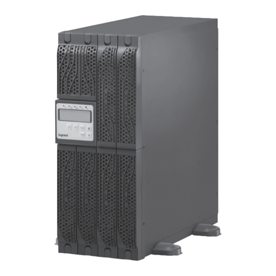
Summary of Contents for LEGRAND Daker DK 4.5-6 kVA
- Page 1 Daker DK 4.5-10 kVA ® Parallel installation quick start Part. LE08927AA-09/15-01 GF...
- Page 2 ® Daker DK 4.5-10 kVA ENGLISH...
-
Page 3: Table Of Contents
Daker DK 4.5-10 kVA Index Introduction 1 Important Safety Instructions 2 Parallel system installation 3 Single Unit Check 4 Parallel Setting 4 Parallel Mode Start up 5 Trouble Shooting... -
Page 4: Important Safety Instructions
® Introduction This document is a reference guide to install the Daker DK UPS 4,5-10kVA in parallel for N+1 redundancy operation. The parallel installation and configuration procedure is divided in 4 phases : Parallel system installation – To physically connect each unit. Single Unit check –... -
Page 5: Parallel System Installation
Daker DK 4.5-10 kVA 2 Parallel system installation Accessories The following accessories (included in the parallel kit) are requested to install the UPS in parallel mode. QUANTITIES ACCESSORIES DESCRIPTION 2 UPS 3 UPS 4 UPS Standard cat5 cable with Rj45 connector (max length: 1050mm) Standard cat5 cable with Rj45 connector... - Page 6 ® 2 Parallel system installation Recommended Circuit Breakers to be installed at the UPS input/output MODEL INPUT (CBi) OUTPUT (CBo) 4,5-6KVA 10KVA The breaker type should be “C” or “D” with the following current ratings: • Install and connect the UPS units according to the diagrams in figure 2, 3, 4, 5. CAUTION The MTBS is an optional for maintenance.
- Page 7 Daker DK 4.5-10 kVA • Connect the parallel CAT5E cables as a “Ring Network” (Figure 3) using the parallel kit plate to fix them to the UPS rear panel (Figure 4) 2 units parallel 3 units parallel 4 units parallel Figure 2 Figure 3 CAUTION...
- Page 8 ® 3 Single Unit Check Parameters Check CAUTION The following operations have to be done on each UPS separately and independently. • Ensure that all the circuit breakers at the input (Cbi) and output (Cbo) are set to off position. •...
- Page 9 Daker DK 4.5-10 kVA Item Display List Press < > Default Press < > to change to change Buzzer on/off Self-Test (Available in Line-Mode Only) Bypass Voltage Range Inverter Synchronize Frequency range Inverter Output Voltage * Operation Mode Output Voltage Adjustment Parallel ID Number **...
- Page 10 ® 3 Single Unit Check CAUTION “Bypass Voltage Range”, “Inverter Synchronize Frequency Range”, “Inverter Output Voltage” and “Output Voltage Adjustment“ are adjustable parameters but for parallel function eve- ry unit must have the same settings • Change item by pressing < > until the display shows the text “Save”. Press < Enter > to save the setting.
-
Page 11: Single Unit Check
Daker DK 4.5-10 kVA 4 Parallel Setting Terminal resistor setting Each UPS unit is equipped with a terminal resistor “S1” placed on the rear panel (Figure 7) besides the RJ45 connectors. • Set the terminal resistor according to the configuration shown in the Table 2 TERMINAL RESISTOR STATUSOUTPUT (CBo) PARALLEL UNITS UPS1... -
Page 12: Parallel Setting
® 4 Parallel Setting • Set the Parallel function to “Enable” (P 02) UPS# UPS#1 UPS#2 UPS#3 UPS#4 ID NUMBER PARALLEL FUNCTION Table 3 Turn off the inverter and then the AC input (Turn off CBi and CB1 of the UPS) and restart the process for the next unit. - Page 13 Daker DK 4.5-10 kVA 4 Parallel Mode Start up Start up procedure • Ensure that the input and output circuit breakers are set to off position for all the UPS. • Turn on the input breaker (CBi and CB1) of all the UPS connected ( all the units are now in by- pass mode) •...
-
Page 14: Trouble Shooting
® 5 Trouble Shooting POSSIBLE ERROR DESCRIPTION CAUSE SOLUTION Er16 Output If an Er16 appear during Possible solution: repeat Parameters the parallel installation test, the process described in the Setting Error then there are one or more paragraph “parameters check“ parameters setting conflict 2and make sure that the between the UPS units. - Page 16 : 33 5 55 06 87 87 Fax : 33 5 55 06 74 55 www.legrandelectric.com Legrand se réserve le droit de modifier à tout moment le contenu de cet imprimé et de communiquer, sous n’importe quelle forme et modalité, les changements apportés.


Need help?
Do you have a question about the Daker DK 4.5-6 kVA and is the answer not in the manual?
Questions and answers