Advertisement
Advertisement
Table of Contents

Summary of Contents for TAWI PRO40
- Page 1 User guide for TAWI Lifting Trolleys...
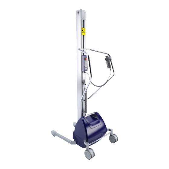
- Page 2 The lifters are available in seven different models, mainly differing in lifting capacity: PRO40, PRO80, PRO140, PRO180, PRO250, PRO100ESE and PRO200ESE. This chapter presents an overview illustration of the lifters and a table containing characteristics of the different models.
- Page 3 This table presents information about STANDARD CONFIGURATIONS of each model. Model PRO40 PRO80 PRO140 PRO180 PRO250 PRO100ESE PRO200ESE Lifting 40kg/ 80kg/ 140kg/ 180kg/ 250kg/ 100kg/ 200kg/ capacity 308lbs 379lbs 88lbs 176lbs 551lbs 220lbs 441lbs Loading on page 04 The lifting capacity is valid only in accordance to the appropriate load diagram, see The max lifting capacity specified above are valid for standard configurations of the lifters.
- Page 4 The max lifting capacity of the lifters depends on where the mass centre of the load is located in terms of x and y distances. The graphs in the load diagrams display allowed x-distances and the text above each load diagram presents allowed y-distances. PRO40, PRO80, PRO140, PRO180 and PRO250 Illustration of x and y-distances Load diagram PRO40 Valid for y-distances between 0 - 1640mm (0 - 64.5in).
- Page 5 Load diagram PRO180 Load diagram PRO250 Valid for y-distances between 0 - 2540mm (0 - 100in). Valid for y-distances between 0 - 2540mm (0 - 100in). PRO100ESE and PRO200ESE Illustration of x and y-distances Load diagram PRO100ESE Valid for y-distances between 0 - 2222mm (0 - 87.4in). (x) mm Load diagram PRO200ESE Valid for y-distances between 0 - 2195mm (0 - 86.4in).
-
Page 6: Quick Start
2 Quick start This chapter presents how to fasten tools and how to start the lifter. Fasten tools on the sleigh Sometimes tools are attached at delivery. If not, at- tach the tool to the sleigh with at least three screws. Select which holes to use in order to get the desired max and min lifting heights. - Page 7 Make sure that the wheels rotate smoothly, that the brakes on the rear wheels are functioning properly and that the battery is charged. Review and perform relevant inspections. See Daily inspections by operator on page 20, Quarterly inspections by inhouse maintenance on page 21 and Yearly inspections by TAWI authorised service technician on page 21.
- Page 8 • The lifter can be switched on or off when charging the battery. It is recommended that the lifter is switched off. • To make sure not to damage the cord when pulling it out of the electrical outlet - grab, and apply the force to the plug.
-
Page 9: Battery Charging Indicator
Battery charging indicator The colour of the battery charging indicator communicates the following information: PRO40 and PRO80 Orange Boost charge Yellow Top up charge Green Ready/standby PRO140, PRO180, PRO250, PRO100ESE and PRO200ESE Yellow (steady) Boost charge Yellow (flashing) Top up charge... - Page 10 Engage or disengage the brakes on both rear wheels. A. Neutral B. Brake Central brake (all models except PRO40) The central brake has three positions; brake, re- lease, and directional lock. Directional lock means that the rear wheels are locked in a fixed position, only allowing the lifter to move straight forward and straight backwards.
- Page 11 Adjust legs This section only applies to PRO80 and PRO140. The legs of these models can be adjusted in width. Always apply brakes and take out the battery pack before leaning the lifter. Also make sure that no cables are in the way or squeezed between the operator handle and the floor.
-
Page 12: Operating Tools
Operating tools Tools are handled using a detachable hand control and the control panel. If the lifter is not equipped with a hand control, only the control panel is used. If a tool hits an object or surface during lowering, a safety mechanism will stop the downwards movement. This is to prevent accidents. -
Page 13: Control Panel
Control panel There are three standard configurations of the control panel, they depend on the model of the lifter. Control panel on lifter Control panel on lifter NOT Control panel on lifter equipped equipped with a hand control. equipped with a hand control. with EasySqueeze. - Page 14 General tools General tools includes platforms, fork tools etcetera, see Tools on page 36 for additional examples. These can be used to raise and lower loads and objects using the hand control and/or the control panel. • Make sure that the load is stable and is secured on the general tool. •...
- Page 15 Grip an object 1. Move the lifter and use the hand control to place the EasySqueeze arms centred in height and depth over the object that is to be moved. 2. Press the Close squeeze arms (B) button and keep it pressed. »...
- Page 16 Release an object • Make sure there is enough space when unloading so that the EasySqueeze arms do not collide with any surrounding items when moving outwards to release the object. • Do not release an object during raising or lowering.
- Page 17 Coregripper The Coregripper is a reel handling tool that handles the reel from the core. It is designed to handle reels with a cardboard core. See Control panel on page 13 for illustrations of the buttons to use when operating an electrical Coregripper.
- Page 18 7. Rotate the Coregripper to horisontal position by grabbing the OPPOSITE side of the handle from the side you stand with reference to the mast. 8. Pull the rotation lock pin outwards and hold. 9. Pull the handle to rotate the reel. 10.
- Page 19 Position stop switch is placed between the top and bottom limit switches. • NEVER move the top or bottom limit switches. The Position stop is configured to stop the tool when the tool moves upwards or downwards. Contact a TAWI authorised service technician for support with configuration of the Position stop.
-
Page 20: Service And Maintenance
• In order to deal with the lifter’s cables and wiring, a good knowledge of electricity and TAWI electrical schedules of the lifters is required. • If the battery needs to be replaced, either order a new battery pack from TAWI or make sure that an original battery is used. If assistance is needed, contact TAWI. - Page 21 1. Double check (carry out) all daily inspections mentioned in Daily inspections by operator. 2. Check all screws and nuts for damage/wear. Yearly inspections by TAWI authorised service technician 1. Check that CE mark and serial number on the identification plate are visible.
-
Page 22: Troubleshoot
5 Troubleshoot This chapter provides information on how to investigate or rectify problems that may occur. Actions marked with (*) must be carried out by TAWI or a TAWI authorised service technician. Main unit Problem Likely caused by Action required Main switch is turned off. - Page 23 Problem Likely caused by Action required Belt transmission is worn in an inappro- Check belt and belt wheels for wear, replace if needed.* priate way. Brake has been misused. Replace rear wheels. Check wires and connections between mother board and Wires or connections are loose.
- Page 24 Tools Problem Likely caused by Action required Any faults of main unit. Check if main unit is working properly. Release pressure from ES arms, make sure lifted object is Overload protection is activated. in secure position before releasing pressure. Actuators are damaged. Replace actuators.* No electrical connection in slip Check connection in slip ring, replace if needed.*...
- Page 25 B. There is a bad connection to the Check all connections. motor. C. The motor has a short circuit to a bat- Contact a TAWI authorised service technician. tery connection. D. N/A E. N/A F. Sleepmode (follows a preset period of inactivity, the function is there to save Restart the lifter.