Table of Contents
Advertisement
Advertisement
Table of Contents

Related Manuals for Bartec R3 Series


Summary of Contents for Bartec R3 Series
- Page 1 ® Thermophil INFRAsmart R300/R301/R302 ® Thermophil INFRAht R310/R311/R312/R320 Operating Instructions BA 040120 BARTEC BENKE GmbH Schulstraße 30 D-94239 Gotteszell Phone (09929)-301-0 Fax (09929)-301-112 Internet: www.bartec-benke.de E-mail: gotteszell@bartec-benke.de...
-
Page 3: Table Of Contents
Contents I - 1 Table of Contents System description ......................... 1 Properties and fields of use ....................1 Sensor versions ........................2 Scope of delivery ........................3 Technical data ........................4 1.4.1 Thermophil ® INFRAsmart ....................4 ® 1.4.2 Thermophil INFRAht ...................... - Page 4 I - 2 Copyright © 2019 by All rights reserved. Subject to change without prior notice. BARTEC BENKE No part of this document may be reproduced, processed or distributed in any form or by any means without the prior written permission of Schulstraße 30...
-
Page 5: System Description
System description System description Properties and fields of use Properties INFRA radiation sensors from the R 3XX series are robust, stationary measuring sensors that are used in connection with indicating devices, controllers recording instruments contact-free temperature measurement and temperature monitoring, control or registration. They enable you to record surface temperatures quickly and reliably even in situations where traditional contact-based measurement is very difficult, is only possible to a limited extent or is not actually possible at all. -
Page 6: Sensor Versions
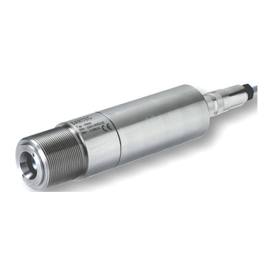
System description Sensor versions The radiation sensors are delivered both in a compact form, with a built-in ® measuring amplifier (Thermophil INFRAsmart), and in a two-part form, with ® a small radiation sensor and a separate measuring amplifier (Thermophil INFRAht). In this case, the radiation sensors and measuring amplifiers are connected using a heat-resistant cable. -
Page 7: Scope Of Delivery
System description ® Thermophil INFRAht TR 40-10 TR 41-10 R 310 / R 311 R 312 R 320 Type R310 Sensor with cone 1.7:1, separate measuring amplifier (TR 41-10 or TR 40-10) Type R311 Sensor with lens 20:1, separate measuring amplifier (TR 41-10 or TR 40-10) Type R312 Sensor with lens 33:1, separate measuring amplifier... -
Page 8: Technical Data
System description Technical data ® 1.4.1 Thermophil INFRAsmart Measuring range max. 0...+ 400 °C with R 300 Overall max. 0...+ 2000 °C with R 301/R 302 Spectral response 8 ...14 µm; 2 ... 2,7µm; 4,9 ... 5,5µm; 7,9µm (R300 only) ®... -
Page 9: Thermophil Infraht
System description Dimensions R 300 R 301 R 302 Distance ratio R 300 R 301 R 302 ® 1.4.2 Thermophil INFRAht Sensors Measuring range max. 0...+400 °C with R 310/R 320 Overall max. 0...+2000 °C with R 311/R 312 Spectral response 8 to 14 µm;... - Page 10 System description Dimensions R 310 / R311 R 312 R 320 Distance ratio R 310 / R320 R 311 R 312 Transmitters For R 310, R 311, R 312, R 320 Input PT100 for ambient temperature (TR 41-10) Interface HART ®...
- Page 11 System description Response time t 0.9 = 0.2 s (without damping) Power supply = DC 12...30 V, max. 25 mA, residual ripple 150 mV eff. Sensor connection Signal Colour Description – – – – Thermistor R– Thermistor Thermopile – U–...
- Page 12 System description Operating Instructions Radiation sensors R3XX...
-
Page 13: Safety Precautions
The equipment must be installed and maintained by qualified technical personnel. Make sure that the data and operating conditions specified by BARTEC are observed. For the utilisation of the IR protection window ZnSe, please observe the safety instructions under chapter 3.3.2. -
Page 14: Electrical Connection
In the event of faults, first determine whether you can rectify them yourself. If this is not possible, switch off the equipment and send it to BARTEC for repair, together with a precise specification of the fault. If you discover any signs of damage or destruction to any parts of the... -
Page 15: Bartec Benke
BARTEC BENKE GmbH and its vicarious agents only assume liability in the case of deliberate acts or gross negligence. The extent of liability in such a case is limited to the value of the order placed with BARTEC BENKE GmbH. -
Page 16: Installation
Sensor In order to prevent inadmissible heating or damage to the sensor in the event that the supply of cooling water is cut off, it is also necessary to monitor the water circulation. BARTEC offers suitable flow control instruments. Note: The Thermophil®... -
Page 17: Measurement Distance
Installation Measurement distance The laws of optics must be taken into account when measuring radiation. Depending on the distance between the radiation sensors and the measurement object there will be certain minimum measuring field diameters – see distance ratio (technical data). The sensor type that is needed in each case, with the appropriate focal length, must be determined in accordance with the required measuring field size at the measurement object and the possible measurement distance. -
Page 18: Aids, Accessories
Depending on the installation conditions and the ambient conditions where the sensor is used, various installation aids and accessories can be used. The following overview lists the accessories that can be delivered. Please feel free to request assistance from BARTEC where required. For sensor Order... - Page 19 Installation For sensor Order Designation Type Dimensions Cooling jacket/air nozzle WN 268 Combined, series B U03012268 Fixed bracket R 300-105 216975 Adjustable bracket R 300-106 216976 ®...
- Page 20 Installation For sensor Order Designation Type Dimensions Test set for testing pyrometers R300-110 R30x 241933 Sensor bracket with air flush R 300-111 242754 Mounting plate for TR40-10 R300-112 245891 ...
- Page 21 Installation For Sensor Order Designation Type Dimensions Pyrometer slewing device R300-116 277319 Connecting kit for pyrometer R300-117 R300-116 slewing device 277409 Cooling water connecting kit for R300-132 R300-116 pyrometer 286185 Pyrometer protection tube R300-118 (stainless steel) 277420 ...
- Page 22 Installation For Sensor Order Designation Type Dimensions Cooling jacket for pyrometer R300-121 279027 Protective cap for pyrometer R300-122 279030 Sensor bracket with air nozzle R300-123 (aluminium) 279031 USB/HART-modem incl.
- Page 23 Installation For Sensor Order Designation Type Dimensions Cleaning kit for pyrometer R300-128 282302 IR silicon slice with seal R300-129 e.g. together with R 300-111, R 300-113 Transmission factor 0,8 285141 ...
- Page 24 Installation für Sensor Beste Bezeichnung Abmessungen ll-Nr. Adapter Schlauchanschluss 6 zu R300-137 8 mm 307181 Anschlussrohr mit Flansch, R300-139 500 mm 319192 Flansch F Führungsrohr R300- R300-140 118/130/131 334137 ...
- Page 25 Installation für Sensor Beste Bezeichnung Abmessungen ll-Nr. Digitalanzeige 830R mit Kabel R300-142 307181 Adapter 1 ½“ AG / M38x1,5 IG R300-143 408812 Mounting nut R 300- 00-024...
- Page 26 Installation für Sensor Beste Bezeichnung Abmessungen ll-Nr. U233085 Connection coupling 4-pole, (90°) U266182 Power supply unit 230 V, output 5906-3 24 V DC in rail-mounting housing U8901159063 Power supply unit 230 V, output 5906-4 24 V DC in surface housing...
- Page 27 Installation For Sensor Order Designation Type Dimensions 4 pole Extension cable, WN 293-5 connector and 4 pole clip 5 m = 314166 8 m = U01110822935 Connection cable, open ends WN 293-6 3 m = U01110322936 6 m = U01110622936 10 m = U01191022936 15 m = 246691...
- Page 28 Installation For Sensor Order Designation Type Dimensions open ends 6 m = 286186 10 m = 286188 15 m = 286189 30 m = 286190 40 m = 286191 50 m = 286192 60 m = 286193 70 m = 286194 Operating Instructions Radiation sensors R3XX...
- Page 29 Installation For Sensor Order Designation Type Dimensions Connection cable WN 293-10 Connection coupling 90° 35 m = 294041 Connection cable Ex WN 293-11 Connection coupling 90° 10 m = 302906 60 m = 290261 Operating Instructions Radiation sensors R3XX...
-
Page 30: Safety Instructions For The Operation Of Laserpointer Type R300-101
Installation 3.3.1 Safety instructions for the operation of Laserpointer type R300-101 To operate the Laserpointer type R300-101, please keep in mind the following instructions: The beam emitted by this LASER is strongly bundled. Caution: Do not look into the laser beam or at direct reflexes of reflecting or polished surfaces - not even by means of optical instruments. -
Page 31: Connection
Installation Connection 3.4.1 R 300, R 301, R 302 The sensors can be connected either using a 4-pole plug or using a connected cable with free ends. 3.4.1.1 Connection via plug R 300 /301 /302 Evaluator Plug connector 4...20 mA Power ... -
Page 32: R 310, R311, R312, R320
Installation 3.4.2 R 310, R311, R312, R320 The sensors are connected to the terminals of the measuring amplifier, Type TR 40-10 or TR 41-10. Sensor connection Signal Colour orange black brown – Power 4...20 mA Disc Shield Shield cone Shield, 14 mm, stripped Cable gland Connection to TR 41-10... - Page 33 Installation – 4...20 mA Shield Sensor connection Signal Colour orange black brown Disc Shield Shield, 14 mm, stripped Cable gland Connection to TR 40-10 Operating Instructions Radiation sensors R3XX...
-
Page 35: Operation
Operation Operation Measurement operation Once the auxiliary power has been switched on, measurement operation can be commenced. Further operation depends on what the sensors are being used for. Please consult the operating instructions for the connected equipment (e.g. display, recording instruments, controllers). Please heed the following during measurement operation: ... -
Page 36: Configuration With Transmitter Tr 41-10
Operation 4.2.1 Configuration with transmitter TR 41-10 Sensors R 310, R 311, R 312 and R 320 can be configured using a connected transmitter, Type TR 41-10. Increase value Mode button Decrease value 4.2.1.1 Configuration process Starting configuration mode In order to start configuration, press the mode button . Selecting parameters Each time you press the mode button ... -
Page 37: Parameters
Operation 4.2.1.2 Parameters The following overview lists the configurable parameters in the order in which they appear on the display when you press the mode button . Password prompt Before you can make any changes to the following parameters, you must enter the valid password here. - Page 38 Operation Maximum mode A “hold time” for maximum values is set here. The maximum value that has occurred in each case is held for the set time and output. If a new maximum value occurs during the hold time, the hold time will begin all over again. The time is set in seconds.
- Page 39 Operation Lower measurement range limit This is where you set the value for the lower measurement range limit. The value defined corresponds to an output signal of 4 mA. Display Minimum value (corresponds to 32 °F) Maximum value 1250 (corresponds 2282 °F) Increment 1 °C (1 °F)
- Page 40 Operation Ambient temperature alarm As soon as the inside temperature of the radiation sensor exceeds the 65.0 defined value, the temperature display will start flashing and the analogue output will switch to the programmed state (see fault current). Display Minimum value 20.0 (corresponds to 68 °F) Maximum value 70.0 or 125.0...
-
Page 41: Default Values
Operation Changing the password Once you have started configuration mode and entered the valid password, this menu for changing the password will appear. Display Minimum value Maximum value 1999 Increment Default value Current password 4.2.1.3 Default values You can reset the equipment to the factory settings and delete the password. -
Page 42: Configuration Of The Sensor Data (Not Implemented)
Operation 4.2.1.4 Configuration of the sensor data (not implemented) After you have exchanged a sensor you need to enter the associated configuration data. You can find the data in the relevant sensor documentation. Before you can enter values you must first enter the valid password (see Section 4.2.1.2, Password prompt). - Page 43 Operation Service register 2 Display Minimum value Maximum value 65535 Increment Default value Meaning Thermistor gradient Service register 3 Display Minimum value Maximum value 65535 Increment Default value Meaning Used Service register 4 Display Minimum value Maximum value 65535 Increment Default value Meaning Cell gradient (part 1)
- Page 44 Operation Service register 8 Display Minimum value Maximum value 65535 Increment Default value Meaning Reserve Service register 9 Display Minimum value Maximum value 65535 Increment Default value Meaning Checksum Error messages If any errors have occurred, they will be displayed once you have left the last service register (S9).
-
Page 45: Test Mode
Operation 4.2.1.5 Test mode In test mode, you can test downstream equipment by outputting defined current values. Starting test mode Keep the button pressed down and additionally press the button for at least 2 seconds. Then let go of the two buttons. The display should then TEST appear as in the screenshot on the left. -
Page 46: Configuration With The Hart Modem, Type R 300-107
Operation ® 4.2.2 Configuration with the HART modem, Type R 300-107 In the case of radiation sensors not operated with a transmitter that has a ® display, configuration is carried out using the R 300-107 HART modem and a PC software solution that is delivered with the modem. ®... -
Page 47: Software
Operation 4.2.2.2 Software Install the HART infrared configuration software that is delivered together ® with the HART modem. Start the HART infrared configuration software. Set the interface parameters as shown in the diagram below, choosing the ® interface that is connected to the HART modem. - Page 48 Operation Changing parameters Once the connection has been set up, the parameters of the connected ® HART unit will be read and displayed. You can enter the configuration data in the “Temperatur Prozess Einstellungen” (temperature process settings) section (see Section 4.2.1.2). Operating Instructions Radiation sensors R3XX...
-
Page 49: Configuration Pactware
Configuration PACTware Configuration PACTware The following installation was carried out on a system running Windows XP Professional Version 2002 SP3. Installation of the INFRA DTM driver for PACTware Insert the supplied installation CD-ROM for the R 300 software into the CD-ROM drive. - Page 50 Configuration PACTware Installation steps: Operating Instructions Radiation sensors R3XX...
- Page 51 Configuration PACTware Installing the isHRT USB interface driver Please refer to the isHRT USB user manual. The driver software must be installed before connecting the device! Insert the supplied installation CD-ROM for the isHRT driver software into the CD-ROM drive. If the installation does not start automatically, call up the setup programme for isHRT Multidriver.
- Page 52 Configuration PACTware Installation steps: Operating Instructions Radiation sensors R3XX...
- Page 53 Configuration PACTware Installing the isHRT FDT driver for PACT- ware Please refer to the isHRT FDT user manual. Insert the supplied installation CD-ROM for the isHRT driver software into the CD-ROM drive. Start the setup programme for isHRT FDT Setup. The installation commences →...
- Page 54 Configuration PACTware Enter the CD code supplied: → Supply your company information (e.g. company, city) → CD code as supplied (e.g. 1111-2222-AAAA-3333-BB44) Operating Instructions Radiation sensors R3XX...
- Page 55 Configuration PACTware Installing PACTware Insert the supplied installation CD-ROM for the R 300 software into the CD-ROM drive. Cancel the installation of the HART Infraconfigurator, as it is not needed in conjunction with PACTware. Decompress the installation archive pw35ics.zip. Start the setup programme (setup.exe) for PACTware.
- Page 56 Configuration PACTware The installation commences → follow the on-screen instructions. Several programme parts are installed. Installation steps: Operating Instructions Radiation sensors R3XX...
- Page 57 Configuration PACTware Configuring the isHRT USB modem You can now connect the isHRT USB modem to your PC. Windows will now install the driver modem. Follow the on-screen instructions. The following should be displayed on-screen, once installation has concluded successfully. You now need to configure the modem.
- Page 58 Start the PACTware programme. Call up the menu point Tools → Manage Device Catalogue. The device entries 'BARTEC Thermophil DTM' and 'isHART USB v2' must be displayed there. Should these entries not be visible, try locating the driver with 'Update Device Catalogue'.
- Page 59 Configuration PACTware Create a new device configuration. Press OK when prompted to add the BARTEC Thermophil DTM driver. Supply the sensor with voltage and connect the HART modem to the sensor. Operating Instructions Radiation sensors R3XX...
- Page 60 Configuration PACTware Read the device data from the sensor. Operating Instructions Radiation sensors R3XX...
-
Page 61: Maintenance
Maintenance Cleaning kit type R300-128 for pyrometers BARTEC pyrometers are very durable and almost maintenance-free. Maintenance is restricted to checking and cleaning the optics. If it is cleaned regularly and carefully, the high reliability of the measuring system can be preserved and guaranteed. - Page 62 Maintenance stream emitted either continuously or as a strong air blast. Change the Air stream position of the air outlet nozzle accordingly. Air blast (press hard!) Use the cleaning spray if there are deposits or hard-sticking dirt particles. Let the fluid take effect for a short time. With a cleaning tissue and by applying only little pressure, carefully wipe off the dissolved dirt.
- Page 63 Maintenance Operating Instructions Radiation sensors R3XX...
-
Page 65: Hart Protocol
HART® protocol ® HART protocol ® The following table contains an overview of the relevant HART commands ® in HART Version 7. No and function Data in the instruction Data in the reply Read unique identifier Read primary variable Byte Range unit code Float Read current and percent of range... - Page 66 HART® protocol No and function Data in the instruction Data in the reply Write damping value for the PV float float average value 0…999.9 s average value 0…999.9 s Write range values for the PV byte byte range unit code range unit code float float...
- Page 67 HART® protocol No and function Data in the instruction Data in the reply Read device data long char[15] Type Software version Description of command 144 Command Data in the instruction Data in the reply float float float float Unimportant Content of service register Display service register no.
- Page 68 HART® protocol Description of command 145 Command Data in the instruction Data in the reply float float float float Value Content of service register Describe service register no. 0 Value [0-65536] Content of service register Describe service register no. 1 Value [0-65536] Content of service register Describe service register no.
-
Page 69: Additional Instructions For Use In Dust-Explosive Areas
Instruction Additional instructions for use in dust-explosive areas This supplementary chapter provides additional instructions for the safe usage of Thermophil INFRAsmart type R300 / R301 / R302 and Thermophil INFRAht Typ R310 / R311 / R312 / R320 with measuring amplifier TR40-10 in potentially explosive areas. - Page 70 Instruction Caution! Before working with circuits and before opening the connection assembly within a potentially explosive area, switch off the power supply of the circuits. Within a potentially explosive area, only the tools and measurement equipment approved for this purpose may be used. Maintenance ...
- Page 71 Instruction Technical data At the (+) and (-) connections of the auxiliary energy (supply / signal circuit) the device has to be supplied with a certified intrinsically safe Ex ib IIC circuit or with a certified intrinsically safe EEx ia IIC circuit with the following maximum values: Maximum input voltage 28 V...
- Page 72 Instruction Operating Instructions Radiation sensors R3XX...
- Page 73 Annex A - 69 Annex Emission factor If you want to measure the temperature of an object without contact, you need to know the emission degree “E” and include it in the measurements. The calibration basis for IR temperature measuring units and control units is the black body with the emission degree E = 1.
- Page 74 Annex A - 70 In practice, it is a good idea to verify the E factor once by taking a comparison measurement. Various measurement procedures may be suitable depending on the circumstances. Drill hole method: A hole with a depth of 2 - 3 mm is drilled into the measurement object and an immersion measurement is taken in the hole using a low-mass sensor (semiconductor or thermal element, ...
- Page 75 Annex A - 71 Transmission factor The transmission factor specifies the percentage of radiation that passes an additional protective window. If you do not have the details of the transmission factor for the protective window used, you can work it out yourself. Determining the transmission factor ...
- Page 76 Operating Instructions Radiation sensors R3XX...
Need help?
Do you have a question about the R3 Series and is the answer not in the manual?
Questions and answers