Table of Contents
Advertisement
Quick Links
Advertisement
Table of Contents

Related Manuals for THUNDER TIGER Mini Titan E325 SE


Summary of Contents for THUNDER TIGER Mini Titan E325 SE
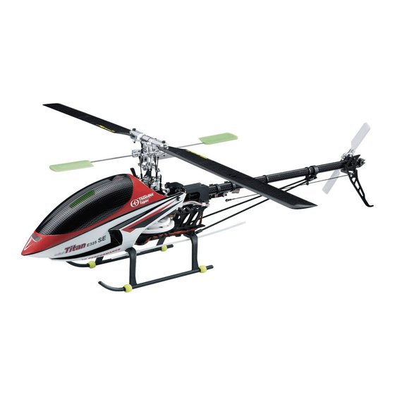
- Page 1 3D PERFORMANCE...
-
Page 2: Table Of Contents
m ini T it a n E3 2 5 SE CON T EN T S Introduction Other Items Required Assembling Section Main Rotor System Linkage Rod Installation Main Frame Assembly Tail Unit Assembly Tail Boom Bracket Set Electric System Canopy Assembly Main Rotor Blade Assembly Introduction of E-CCPM Control System Servo Connecting... -
Page 3: Introduction
Therefore, extreme caution must be exercised during operation. 2.Thunder Tiger ensures parts packaged in this product is of the highest quality. However, after assembly and usage, parts damaged due to wear or misuse will not be replaced under any circumstances. -
Page 4: Step
FLI GH T SAFET Y CH ECK LI ST 1.Make sure that the transmitter battery is fully charged before flying. 2.Make sure all control surfaces are operated properly before flying. 3.Do a range check of the radio before the first flight. The electronic equipment must operate properly at a range of at least 15 meters (50 ft) even with the transmitter antenna collapsed. -
Page 5: Other Items Required
OTHER ITEMS REQUIRED RADIO SET Servos Transmitter Receiver Gyro (Control Surface x3, (helicopter type only, Rudder Servo x1) 6 or more channels) POWER SYSTEM Speed Control Li-Po Battery Battery Charger Brushless Motor TOOLS REQUIRED FOR ASSEMBLY Diagonal Pliers Screw Driver Needle Nose Pliers Ball Link Pliers Scissors... -
Page 6: Assembling Section
ASSEMBLING SECTION The parts in the E325 SE kit are packed according to the assembly steps. The part number and quantity are always shown in the square box on each page. Do not open all the bags at once. Open only the bag that is needed for the current assembly step. -
Page 7: Main Rotor System
Bag A Main Rotor-1 Description Q'ty Description Q'ty Collar, d2xD3x2.7 Metal Main Rotor Hub Shoulder Screw, M2x6 Metal Seesaw Hub 1.Slide in the Metal Seesaw Hub to the Main Step 2 Rotor Hub. 1.Turn the Metal Seesaw Hub 90 degree. 2.Mind the direction of the Metal Seesaw Hub. - Page 8 Bag A Main Rotor-2 Description Q'ty Description Q'ty Metal Mixing Lever Countersunk Screw, M1.6x6 Collar, d3xD6x5.6 Flat Washer, d2xD3.7x0.5 Linkage Ball, ø3.8 Shouldered Screw, M2x9 Step 1 Secure the Linkage Balls to the Mixing Lever. Step 2 1.Secure the Metal Mixing Lever to the Metal Seesaw Hub. 2.Make sure that the Metal Mixing Lever can be rotated freely.
- Page 9 Bag B Main Rotor-3 Description Q'ty Description Q'ty Metal Flybar Control Arm SUS Flybar Rod Metal Flybar Control Post Set Screw, M3x3 Linkage Ball, ø3.8 Paddle(Standard) Countersunk Screw, M1.6x6 Paddle(3D) Step 1 Step 2 1.Secure the Linkage Ball to the Metal Flybar 1.Slide the Flybar through the Metal Seesaw Control Post.
- Page 10 Bag B Main Rotor-4 Description Q'ty Description Q'ty Linkage Ball, ø3.8 Flap Damper Countersunk Screw, M1.6x6 Collar, ø4xø7 Metal Rotor Grip Flat Washer, d2.6 Feathering Shaft Socket Screw, M2.6x8 Step 1 1.Secure the Linkage Balls to the Main Rotor Pitch Housing. 2.Insert the Flap Damper in the Main Rotor Hub.
- Page 11 Bag B Main Rotor-5 Q'ty Description Hardened Main Shaft Socket Screw, M2x14 Nut, M2 Step 1 1.Slide the Main Rotor Hub Set on to the Main Shaft. 2.Mind the direction of the Main Shaft. 3.Fit the Screw and the Nut to fix the Main Rotor Hub and the Main Shaft.
- Page 12 Bag C Main Rotor-6 Description Q'ty Description Q'ty Metal Flybar Control Lever Flat Washer, d2xD3.7x0.5 Washout Linkage Shoulder Screw, M2x9 Countersunk Screw, M1.7x7 Metal Washout Base Collar, d2xD3x5.6 Metal Swashplate Countersunk Screw, M1.6x6 Main Shaft Lock Ring Linkage Ball, ø3.8 Set Screw, M3x3 Step 1 1.Secure the Washout Linkage to the Metal Flybar Control Lever and make sure that the...
-
Page 13: Linkage Rod Installation
Bag D Linkage Rod Installation Material No. Description Material No. Description Ball Link 3.8x10mm Llinkage Rod 1.3x10mm BK0932 BK1064 Llinkage Rod 1.3x7mm Llinkage R od 1.3x24.5mm BK1063 BK1066 Ball Link 3.8x12mm Llinkage Rod 1.3x29mm BK0922 BK1065 Step 1 1.Assemble the Linkage Rods and the Ball Links. 2.The length is measured from the center of the Ball Links to the other. -
Page 14: Main Frame Assembly
Main Frame Assembly- 1 Ba g E Description Q'ty Description Q'ty Main Frame Landing Skid(Black) Base Plate Tapping Screw(w/washer), M2x6 St e p 1 Assemble the Main Frame and the Base Plate with 6 self-tapping screws. St e p 2 Attach the Landing Skid to the Base Plate with 4 self-tapping screws. - Page 15 Main Frame Assembly- 2 Ba g F Description Q'ty Bearing, d5xD11x5 Upper BRG Housing Tapping Screw(w/washer), M2x10 St e p 1 Fit the Bearing into the Upper BRG Housing. St e p 2 1.Slide the Upper BRG Housing into the Main Frame. 2.Fix the Upper BRG Housing with 4 self-tapping screws.
- Page 16 Main Frame Assembly- 3 Ba g F Description Q'ty Description Q'ty Servo Tray(Right) Tapping Screw(w/washer), M2x10 Servo Tray(Left) Tapping Screw(w/washer), M2x6 Metal Frame Spacer Battery Tray Metal Canopy Retaining Post Phasing Control Track St e p 1 1.Secure the Servo Tray to the Main Frame. 2.Slide the Phasing Control Track onto the Main Frame and fix it with 2 Tapping Screw.
- Page 17 Main Frame Assembly- 4 Ba g G Description Q'ty Autorotation Tail Drive Gear Main Gear (W/Bearing) Flat Washer d6xD10x0.3 One Way Bearing Shaft 1.The One Way Bearing and the Spacer are pre-assembled. 2.Assemble the Main Gear and the Autorotation Tail Drive Gear with the One Way Bearing Shaft.
- Page 18 Main Frame Assembly- 5 Ba g G Description Q'ty Socket Screw M2x14 M2 Nut Set Screw Bearing d5xD11x5 Main Shaft Lock Ring 1.Install the Bearing into the Base Plate. 2.Slide the Main Gear Assembly into the Main Frame. 3.Slide the Main Shaft through the Upper BRG Housing, the Main Gear Assembly and the Lower Bearing.
-
Page 19: Tail Unit Assembly
Tail Unit Assembly- 1 Ba g H Description Q'ty Description Q'ty Carbon Tail Boom Tail Rotor Shaft Set Belt MXL-3tx413T Bearing d3xD8x4t Tail Unit Housing Tapping Screw(W/Washer) M2x10 Tail Unit Housing Cover St e p 1 Insert the Tail Rotor Drive Belt through the Tail Boom so that it comes out of both ends. - Page 20 Tail Unit Assembly- 2 Ba g H Description Q'ty Description Q'ty Countersunk Screw, M2x6 Metal Tail Pitch Control Lever-1 Metal Tail Pitch Control Set Metal Tail Pitch Control Lever-2 Double Joint Lever Linkage Ball Socket Screw, M2x16 Countersunk Screw, M1.6x6 Flat Washer, d2xD3.7x0.5 St e p 1 St e p 2...
- Page 21 Tail Unit Assembly- 3 Ba g I Q'ty Description Q'ty Description Bearing, d2xD5x2.5 Metal Tail Pitch Housing Safety Washer Metal Tail Pitch Link Socket Screw, M2x8 Shouldered Screw, M2x9 Tail Rotor Blade Tail Rotor Hub St e p 1 1.Secure the Metal Tail Pitch Control Link to the Metal Tail Pitch Housing. Mind the chamfer of the link.
- Page 22 Tail Unit Assembly- 4 Ba g I Description Q'ty Set Screw, M3x3 Shouldered Screw, M2x9 St e p 1 Secure the Tail Rotor Hub Set onto the Tail Rotor Shaft. Make sure that the Set Screw should be right on the dot of the shaft. Do not forget apply Loctite on the Set Screw.
- Page 23 Tail Unit Assembly- 5 Ba g I Description Q'ty Carbon Vertical Fin Tapping Screw(w/washer), M2x10 St e p 1 Secure the Carbon Vertical Fin to the Tail Unit. St e p 2 Complete -22-...
-
Page 24: Tail Boom Bracket Set
Tail Boom Bracket Set-1 Ba g J Description Q'ty Tail Boom Bracket Metal Tail Drive Gear Set Tail Boom Bracket Cover Tapping Screw, M2x10 St e p 1 1.Fit the Metal Tail Drive Gear Set to the Tail Boom Bracket. 2.Secure the Tail Boom Bracket Cover to the Tail Boom Bracket. - Page 25 Tail Boom Bracket Set- 2 Ba g J Description Q'ty Socket Screw, M2x12 Nut, M2 St e p 1 1.Pull the belt through the Tail Boom Bracket and keep the belt correctly aligned. 2.Push the Tail Boom into the Tail Boom Bracket and the Tail Drive Belt must be rotated as shown below.
- Page 26 Tail Boom Bracket Set-3 Ba g J Description Q'ty Rod Guide Tapping Screw M1.2x6 Tail Servo Tray Tapping Screw(W/Washer) M2x10 St e p 1 1.Install the Rod Guides and the Tail Servo Tray. 2.Secure the self-tapping screws but not tighten them at this moment so that you can adjust later.
- Page 27 Tail Boom Bracket Set-4 Ba g J Description Q'ty Tapping Screw(w/washer), M2x10 Socket Screw, M2x25 Nut, M2 St e p 1 1.Slide the Tail Boom Set into the Main Frame. 2.Push it on the bracket instead of pushing the Tail Boom. 3.Secure the Tail Boom Set and do not forget to add Loctite on the screws.
-
Page 28: Electric System
Electric System- 1 Ba g K Description Q'ty Description Q'ty Drive Gear, 13T Motor Mount Socket Screw, M3x10 Socket Screw, M3x5 Nylon Nut, M3 Set Screw, M3x3 St e p 1 1.Mount the motor to the Motor Mount. 2.Secure the Drive Gear to the motor shaft. Note that the distance from the end of the Drive Gear to the Motor Mount should be around 16mm as shown. - Page 29 Electric System- 2 Ba g L Description Q'ty Linkage Ball, ø3.8 Countersunk Screw, M1.6x6 St e p 1 1.Remove the servo wheel prior to attaching the Linkage Ball. 2.Mount the Linkage Ball at 12.5mm from the center of the servo arm. 3.Secure the servo to the right Servo Tray and attach the rod to the servo arm.
- Page 30 Electric System- 3 Ba g L Description Q'ty Description Q'ty Tail Linkage Rod Socket Screw, M2x14 Ball Link, ø3.8x12 Nut, M2 Linkage Ball, ø3.8 Tapping Screw(w/washer), M2x10 Carbon Rod, D3x255mm Countersunk Screw, M1.6x6 Tail Support Rod End Bracket St e p 1 1.Apply CA or Epoxy when assembling the Tail Support Rod End.
- Page 31 Electric System- 4 Ba g L Description Q'ty Antenna Tube Rubber Tube, 10mm Landing Skid Damper St e p 1 1.Attach the receiver, gyro to the Main Frame by Double Side Tap. 2.Insert the Antenna Tube and fix it by the Rubber Tube. Gyro Double Side Tap Receiver...
-
Page 32: Canopy Assembly
Canopy Assembly Ba g M Description Q'ty Canopy Body Tapping Screw M1.2x3 Rubber Grommet St e p 1 1.Cut off the unnecessary part from the body and the canopy. 2.Attach the canopy to the body by 3 self-tapping screws. 3.Insert the Rubber Grommet to the body as shown. St e p 2 Cut the Body as shown. -
Page 33: Main Rotor Blade Assembly
Main Rotor Blade Assembly Description Q'ty N ot e : Wood / Carbon Main Blade Rotor Spacer Socket Screw, M3x20 Nylon Nut, M3 Upper Blade Grip Lower Blade Grip Countersunk Screw M1.6x6 For Wood Bla de s: St e p 1 1.For safety concern, be sure to modify the main blades as following. -
Page 34: Introduction Of E-Ccpm Control System
INTRODUCTION OF E-CCPM CONTROL SYSTEM The E-CCPM(Electric Cyclic/Collective Pitch Mixing) system offers the users a control system that can accomplish the same control as traditional M-CCPM(Mechanical Cyclic/Collective Pitch Mixing) system, but with simple machinery. The 120*E-CCPM system utilizes 3 servos for the main control of aileron, elevator and collective pitch. - Page 35 MOVEMENT OF 120°∘ E CCPM SYSTEM The given inputs are executed by the team work of the 3 servos through the mixing program of the radio or the electronic mixer. The following are the examples showing how the movement be carried out.
- Page 36 MOVEMENT OF 120°∘ E CCPM SYSTEM ELEVATOR The elevator is controlled by all of the 3 servos. When an elevator command is given, the 2 servos in the front move in the same direction and the third one move contrary. For example, when a down elevator command is given, the 2 front servos pull the swashplate downward and the third one push the swashplate upward so that the down elevator command is executed.
-
Page 37: Servo Connecting
SERVO CONNECTING E-CCPM system requires 3 channel for aileron, elevator and an AUX(for pitch). But people may get confused because the 3 channels are not referred to any independent movement. They are operated together to carry out the rolling, flipping and collective controlling. As a result, the following connecting manner is recommended. - Page 38 BASIC CONCEPT OF ADJUSTMENT Because people may be confused with the operating manner of the E-CCPM system, we want to explain the basic concept of how to center and trim the servo while adjusting the full travel distance. First of all, we have to make it clear about what do you want to adjust. Do you want to adjust the servo itself or the control surface? For example, if you want to adjust the servo which is plugged into the aileron channel itself, only the servo will be adjusted.
-
Page 39: Concept Of Basic Setting And Adjustment
CONCEPT OF BASIC SETTING AND ADJUSTMENT Before starting, make sure the following preparation is done. 1. Set all trims, knobs, and switches to the neutral and zero position. 2. Reset the radio to its factory preset position. 3. Choose the 120*E-CCPM swashplate control mode. Reversing/Swash Mixing The moving direction of servos has to be confirmed. - Page 40 CONCEPT OF BASIC SETTING AND ADJUSTMENT Level the Swashplate After centering the servos, setting the length of the control linkages and attaching them to the link balls, it is important to check the swashplate that it is level. Turn on the transmitter and the receiver, do not connect the Motor at this moment, and center the collective pitch stick.
- Page 41 COLLECTIVE TO CYCLIC MIXING ADJUSTMENT It always happens that the travel of each servo varies slightly. If so, the swashplate would be tilted when giving a full collective pitch command. These variations can be corrected by altering the travel value of each servo slightly by using the “Travel Adjustment” function. Pitch to Aileron Mixing Place the collective stick to the full positive pitch position.
- Page 42 COLLECTIVE TO CYCLIC MIXING ADJUSTMENT Pitch to Elevator Mixing Through the previous step, we’ve got rid of the pitch to aileron mixing. It is as important to vanish the pitch to elevator mixing. Place the collective stick to the full positive pitch position. Check the swashplate from a side of the model to insure if it’s level from head to rear.
-
Page 43: Setting Up Of Linkage
SETTING UP OF LINKAGE The lengths of the linkage rods are recommended as the following: 18mm 25mm 41.5mm 20mm 36.5mm Lengths are measured from ball link center to ball link center. The pushrod length above is suitable for beginner and 3D flying. You can use those lengths as the starting setting, and adjust the lengths for your flying style. - Page 44 Main Frame Assembly- 2 SETTING UP MAIN ROTOR COLLECTIVE PITCH ANGLE Since you have been setting the lengths of the pushrod as mentioned, the linkage should be centered well as described below. Centering 1. The levers should be as the drawing below while centering the collective pitch stick.
- Page 45 SETTING UP DATA FOR YOUR REFERENCE The following is the setting up data of pitch curve and throttle curve for your reference only. Please ask experienced pilot to help you if you have never done this before. Beginner Throttle Curve Pitch Curve Throttle Curve Thro.
- Page 46 TAIL CONTROL AND GYRO SETUP It is recommended to use a Heading Hold Gyro. With a Heading Hold Gyro, you may not use the trim and the revolution mixing function of tail control. First, choose the length of the tail servo arm referring to the manual of the Gyro.
- Page 47 USING OF LI- PO BATTERY The mini Titan E325 SE is an electric RC helicopter. It is strongly recommended to use Lithium Polymer Battery. Please refer to the following information and precaution: 1. Do use a charger that is designed for Li-Poly batteries only.
-
Page 48: Trouble Shooting
TROUBLE SHOOTING Helicopters Q: What would you check when the helicopter shakes during flying? Are the main blades out of track? Are the paddles out of track? Are the main blades well balanced? Are the paddles well mounted at the same distance from the rotor shaft? Is the spindle or the flybar bent? Is the main shaft bent? - Page 49 TROUBLE SHOOTING The pinion would be 150T/11.33=13.24 So we choose 13T as the motor pinion. Q: Which motor and speed control is recommended? A: The TT OBL29/37-10H optional brushless motor(No.2382) and the ACE BLC-40(No.8041-H) speed control are recommended. -48-...
-
Page 54: Optional Parts
E325 SE OPTIONAL PARTS PV0730 PV0731 PV0810 PV0811 PINION 10T(2)(FOR 2.3mm SHAFT) PINION 15T METAL BRG BLOCK METAL SERVO TRAY PV0819 PV0828 PV0830 PV0831 M. D. JOINT LEVER SETTING WEIGHT PINION 11T (d2.3) PINION11 (d3.17) PV0833 PV0832 PV0836 PINION14T PINION12T BODY (PELLUCID) -53-... -
Page 55: Heli Accessories
E325 SE ACCESSORIES 1198 2382 2532 2808 BALL LINK REAMER (3.8mm) BL. MOTOR, OBL 29/37-10H LI-PO BATTERY E-CHARGER, ELC4 LI-PO BATT,3S1P/2200mAh/20C 8041-H 8117 8131 AQ0836 SPEED CONTROL, BLC-40 ACE MICRO SERVO , C1016 ACE MICRO SERVO , C0915 GOLD CONNECTORS(3.5mm) AQ0837 PV0835 GOLD CONNECTORS(4mm) -
Page 56: Specifiction And Features
SPECI FI CAT I ON Fuselage length: 654 mm (25.74 in) Fuselage width: 120mm (4.72 in) Total height: 210mm (8.3 in) Main rotor dia.: 728mm (28.66 in) / Max.748mm (29.45 in) Tail rotor dia.: 156mm (6.14 in) Gear ratios: 1 : 10 : 4.4 1 : 11.5 : 4.4 1: 15 : 4.4 Full equipped weight:... - Page 57 -56- JK0264...
- Page 58 THUNDER TIGER CORPORATION www.thundertiger.com C 2007...
Need help?
Do you have a question about the Mini Titan E325 SE and is the answer not in the manual?
Questions and answers