Table of Contents
Advertisement
Quick Links
Advertisement
Table of Contents

Related Manuals for Asus ROG Maximus XI Gene


Summary of Contents for Asus ROG Maximus XI Gene
- Page 1 MAXIMUS XI GENE...
- Page 2 Product warranty or service will not be extended if: (1) the product is repaired, modified or altered, unless such repair, modification of alteration is authorized in writing by ASUS; or (2) the serial number of the product is defaced or missing.
-
Page 3: Table Of Contents
Contents Safety information ...................... vi About this guide ......................vii ROG MAXIMUS XI GENE specifications summary..........ix Package contents ..................... xiv Installation tools and components ................xv Chapter 1: Product Introduction Motherboard overview ................1-1 1.1.1 Before you proceed ..............1-1 1.1.2... - Page 4 3.6.13 HDD/SSD SMART Information ..........3-20 Monitor menu ................... 3-21 Boot menu ....................3-21 Tool menu ....................3-23 3.9.1 ASUS EZ Flash 3 Utility ............3-23 3.9.2 ASUS Secure Erase..............3-24 3.9.3 ASUS User Profile..............3-25 3.9.4 ROG OC Panel H-Key Configure ..........3-25 3.9.5...
- Page 5 3.11 Updating BIOS ..................3-28 3.11.1 EZ Update ................. 3-28 3.11.2 ASUS EZ Flash 3 ..............3-29 3.11.3 ASUS CrashFree BIOS 3 ............3-31 Chapter 4: RAID Support RAID configurations .................. 4-1 4.1.1 RAID definitions ................4-1 Appendix Q-Code table ......................A-1 Notices ........................
-
Page 6: Safety Information
Safety information Electrical safety • To prevent electrical shock hazard, disconnect the power cable from the electrical outlet before relocating the system. • When adding or removing devices to or from the system, ensure that the power cables for the devices are unplugged before the signal cables are connected. If possible, disconnect all power cables from the existing system before you add a device. -
Page 7: About This Guide
Refer to the following sources for additional information and for product and software updates. ASUS website The ASUS website (www.asus.com) provides updated information on ASUS hardware and software products. Optional documentation Your product package may include optional documentation, such as warranty flyers, that may have been added by your dealer. - Page 8 Conventions used in this guide To ensure that you perform certain tasks properly, take note of the following symbols used throughout this manual. DANGER/WARNING: Information to prevent injury to yourself when trying to complete a task. CAUTION: Information to prevent damage to the components when trying to complete a task.
-
Page 9: Rog Maximus Xi Gene Specifications Summary
Turbo Boost Technology 2.0* ® * Intel Turbo Boost Technology 2.0 support depends on the CPU type ® ** Refer to www.asus.com for CPU support list Intel Z390 Chipset ® Chipset 2 x DIMM, Max. 64*GB DDR4 4600+(OC) / 4500(OC) / 4400(OC) - Page 10 ROG MAXIMUS XI GENE specifications summary Intel I219-V Gigabit LAN- Dual interconnect between the integrated ® Media Access Controller (MAC) and physical layer (PHY) Anti-surge LANGuard Intel Wireless-AC 9560 ® 2 x 2 Wi-Fi with MU-MIMO 802.11 a/b/g/n/ac supports dual frequency band 2.4/5 GHz...
- Page 11 ROG MAXIMUS XI GENE specifications summary Extreme Engine Digi+ - MicroFine Alloy Choke - NexFET MOSFETs - 10K Black Metallic Capacitors Codensatation detection circuit ROG DIMM.2 extension card with two M.2 slots ProbeIt Start Button Reset Button ReTry Button Safe Boot Button...
- Page 12 ROG MAXIMUS XI GENE specifications summary 1 x Clear CMOS Button 1 x BIOS Flashback Button 1 x PS/2 Combo port 1 x HDMI 1.4b 2 x USB 2.0 Ports Back I/O Ports 1 x Anti-surge LAN (RJ45) port 2 x USB 3.1 Gen 1 ports [blue] 4 x USB 3.1 Gen 2 ports (3 x Type-A [red] and 1 x Type-C™...
- Page 13 WinRAR Windows 10 64-bit Operating System ® Support Micro ATX Form Factor, 9.6 inch X 8.9 inch(24.4 cm x 22.6cm) Form Factor Specifications are subject to change without notice. Please refer to the ASUS website for the latest specifications. xiii...
-
Page 14: Package Contents
Package contents Check your motherboard package for the following items. Motherboard 1 x ROG MAXIMUS XI GENE motherboard 1 x 2-in-1 SATA 6Gb/s cables Cables 1 x Extension Cable for RGB Strips (80cm) 1 x 2x2 dual-band Wi-Fi moving antennas 1 x Q-Connector 1 x ROG DIMM.2 with Heatsink... -
Page 15: Installation Tools And Components
Installation tools and components Intel LGA1151 CPU ® Intel LGA1151 compatible CPU Fan ® Phillips (cross) screwdriver SATA hard disk drive PC chassis DIMM 1 bag of screws Power supply unit SATA optical disc drive (optional) Graphics card (optional) M.2 SSD module (optional) The tools and components in the table above are not included in the motherboard package. -
Page 17: Chapter 1: Product Introduction
Unplug the power cord from the wall socket before touching any component. • Before handling components, use a grounded wrist strap or touch a safely grounded object or a metal object, such as the power supply case, to avoid damaging them due to static electricity. • Hold components by the edges to avoid touching the ICs on them. • Whenever you uninstall any component, place it on a grounded antistatic pad or in the bag that came with the component. • Before you install or remove any component, ensure that the ATX power supply is switched off or the power cord is detached from the power supply. Failure to do so may cause severe damage to the motherboard, peripherals, or components. ROG MAXIMUS XI GENE... -
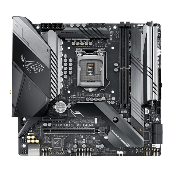
Page 18: Motherboard Layout
1.1.2 Motherboard layout Refer to 1.1.9 Internal connectors and 2.3.1 Rear I/O connection for more information about rear panel connectors and internal connectors. Chapter 1: Product Introduction... - Page 19 19. Intel Z390 Serial ATA 6 Gb/s connectors (7-pin SATA6G_1-4) 1-17 ® 20. Water in, water out, and water flow connectors 1-23 (2-pin W_IN2; 2-pin W_OUT2; 3-pin W_FLOW2) 21. System panel connectors (10-1 pin F_PANEL) 1-26 22. 80 light jumper (3-pin 80_LIGHT) 1-12 23. Motherboard light bar jumper (3-pin MB_LIGHT_BAR) 1-13 24. USB 2.0 connectors (10-1 pin USBE34, USBE56) 1-20 25. Node connector (12-1 pin NODE) 1-24 26. ProbeIt 1-28 27. Thermal sensor connector (2-pin T_SENSOR) 1-18 28. Front panel audio connector (10-1 pin AAFP) 1-18 29. LED connectors (8-pin LED_CON1) 1-20 ROG MAXIMUS XI GENE...
-
Page 20: Central Processing Unit (Cpu)
1.1.3 Central Processing Unit (CPU) This motherboard supports Intel socket 1151 for 9000 series, 8th Generation Core™ i7/i5/i3, ® Pentium and Celeron processors, with memory and PCI Express controllers integrated to ® ® support dual-channel (2 DIMM) DDR4 memory and 16 PCI Express 3.0/2.0 lanes. Ensure that you install the correct CPU designed for LGA1151 socket only. DO NOT install a CPU designed for LGA1150, LGA1155, and LGA1156 sockets in the LGA1151 socket. • Ensure that all power cables are unplugged before installing the CPU. • Upon purchase of the motherboard, ensure that the PnP cap is on the socket and the socket contacts are not bent. Contact your retailer immediately if the PnP cap is missing, or if you see any damage to the PnP cap/socket contacts/motherboard components. ASUS will shoulder the cost of repair only if the damage is shipment/ transit-related. • Keep the cap after installing the motherboard. ASUS will process Return Merchandise Authorization (RMA) requests only if the motherboard comes with the cap on the LGA1151 socket. • The product warranty does not cover damage to the socket contacts resulting from incorrect CPU installation/removal, or misplacement/loss/incorrect removal of the PnP cap. Chapter 1: Product Introduction... -
Page 21: System Memory
1.1.4 System memory The motherboard comes with two (2) Double Data Rate 4 (DDR4) Dual Inline Memory Modules (DIMM) slots. A DDR4 module is notched differently from a DDR, DDR2, or DDR3 module. DO NOT install a DDR, DDR2, or DDR3 memory module to the DDR4 slot. Recommended memory configurations ROG MAXIMUS XI GENE... - Page 22 Memory configurations You may install 2 GB, 4 GB, 8 GB, and 16 GB unbuffered and non-ECC DDR4 DIMMs into the DIMM sockets. You may install varying memory sizes in Channel A and Channel B. The system maps the total size of the lower-sized channel for the dual-channel configuration. Any excess memory from the higher-sized channel is then mapped for single-channel operation. • The default memory operation frequency is dependent on its Serial Presence Detect (SPD), which is the standard way of accessing information from a memory module. Under the default state, some memory modules for overclocking may operate at a lower frequency than the vendor-marked value. • For system stability, use a more efficient memory cooling system to support a full memory load (4 DIMMs) or overclocking condition. • Always install the DIMMS with the same CAS Latency. For an optimum compatibility, we recommend that you install memory modules of the same version or data code (D/C) from the same vendor. Check with the vendor to get the correct memory modules. Chapter 1: Product Introduction...
-
Page 23: Expansion Slots
1.1.5 Expansion slots Unplug the power cord before adding or removing expansion cards. Failure to do so may cause you physical injury and damage motherboard components. Slot No. Slot Description PCIe 3.0 x4 slot PCIe 3.0 x16/x8 slot ROG MAXIMUS XI GENE... -
Page 24: Onboard Buttons And Switches
1.1.6 Onboard buttons and switches Onboard buttons and switches allow you to fine-tune performance when working on a bare or open-case system. This is ideal for overclockers and gamers who continually change settings to enhance system performance. Power-on button (START) The motherboard comes with a power-on button that allows you to power up or wake up the system. The button also lights up when the system is plugged to a power source indicating that you should shut down the system and unplug the power cable before removing or installing any motherboard component. - Page 25 Refer to section 1.1.8 Onboard LEDs for the exact location of the MEM LED. • The DRAM LED also lights up when the DIMM is not properly installed. Turn off the system and reinstall the DIMM before using the MemOK! II function. • The MemOK! II switch does not function under Windows OS environment. ® • During the tuning process, the system loads and tests pretest profiles. It takes about 30 seconds for the system to test one set of profiles. If the test fails, the system reboots and tests the next set of profiles. The system will reboot multiple times when training, once the system has completed the training process the Mem_LED will turn off, please refrain from doing anything before the Mem_LED turns off. • Due to memory tuning requirement, the system automatically reboots when each profile is tested. If the installed DIMMs still fail to boot after the whole tuning process, and the Mem_LED is turned off, please refer to the Q-code LED and Q-code table for more details on the error. • If you turn off the computer and replace DIMMs during the tuning process, the system continues memory tuning after turning on the computer. To stop memory tuning, turn off the computer and unplug the power cord for about 5–10 seconds, then set the MemOK! II switch to disabled. • Ensure to replace the DIMMs with ones recommended in the Memory QVL (Qualified Vendors Lists) at www.asus.com. • We recommend that you download and update to the latest BIOS version from www.asus.com after using the MemOK! II function. ROG MAXIMUS XI GENE...
- Page 26 Safe Boot button (SAFE_BOOT) The Safe Boot button can be pressed anytime to force the system to reboot into the BIOS safe mode. This button temporarily applies safe settings to the BIOS while retaining any overclocked settings allowing you to modify the settings causing boot failure. Use this button when overclocking or tweaking the settings of your system. ReTry button (RETRY_BUTTON) The ReTry button is specially designed for overclockers and is most useful during the booting process where the Reset button is rendered useless. When pressed, it forces the system to reboot while retaining the same settings to be retried in quick succession to achieve a successful POST. Chapter 1: Product Introduction 1-10...
- Page 27 Slow Mode Switch (SLOW_MODE) Slow Mode Switch is employed during LN2 benching. The system may crash due to the CPU being unstable when using extreme overclocking, enabling slow mode will decrease the processor frequency and stabilize the system, allowing overclockers to keep track of their overclocking data. Pause switch (PAUSE) The pause switch allows you to freeze the cooling system at a hardware level, thus allowing you to adjust your system settings under heavy overclocking. ROG MAXIMUS XI GENE 1-11...
-
Page 28: Jumper
1.1.7 Jumper LN2 Mode jumper (3-pin LN2_MODE) With LN2 mode activated, the ROG motherboard is optimized to remedy the cold-boot bug during POST and help the system boot successfully. 80 light jumper (3-pin 80_LIGHT) This jumper allows you to enable or disable the onboard Q-CODE LED. Chapter 1: Product Introduction 1-12... - Page 29 Motherboard light bar jumper (3-pin MB_LIGHT_BAR) This jumper allows you to enable and disable the motherboard back light. ROG MAXIMUS XI GENE 1-13...
-
Page 30: Onboard Leds
1.1.8 Onboard LEDs Q LED (BOOT, VGA, DRAM, CPU) Q LED check key components (CPU, DRAM, VGA card, and booting devices) in sequence during motherboard booting process. If an error is found, the corresponding LED remains lit until the problem is solved. This user-friendly design provides an intuitive way to locate the root problem within seconds. The Q LEDs provide the most probable cause of an error code as a starting point for troubleshooting. The actual cause may vary from case to case. Condensation detection LEDs These LEDs will light up when water condensation is detected on the corresponding critical key components (CPU, DRAM, and PCIE). This user-friendly design helps you quickly identify possible damages caused by condensation. Chapter 1: Product Introduction 1-14... - Page 31 Hard Disk LED (HD_LED) The Hard Disk LED is designed to indicate the hard disk activity. It blinks when data is being written into or read from the hard disk drive. The LED does not light up when there is no hard disk drive connected to the motherboard or when the hard disk drive does not function. Memory LED (Mem_LED) The Mem_LED will light up and remain lit while the MemOK! II function is in use. When the re-training is complete, the Mem_LED will turn off. ROG MAXIMUS XI GENE 1-15...
- Page 32 Q-Code LED The Q-Code LED design provides you with a 2-digit error code that displays the system status. • The Q-Code LED provides the most probable cause of an error code as a starting point for troubleshooting. The actual cause may vary from case to case. • Please refer to the Q-Code table in the Appendix section for more details. Chapter 1: Product Introduction 1-16...
-
Page 33: Internal Connectors
Z390 Serial ATA 6 Gb/s connectors (7-pin SATA6G_1-4) ® These connectors connect to Serial ATA 6 Gb/s hard disk drives via Serial ATA 6 Gb/s signal cables. If you installed Serial ATA hard disk drives, you can create a RAID 0, 1, 5, and 10 configuration with the Intel Rapid Storage Technology through the onboard Intel ® ® Z390 chipset. • These connectors are set to [AHCI] by default. If you intend to create a Serial ATA RAID set using these connectors, set the SATA Mode Selection item in the BIOS to [Intel RST Premium With Intel Optane System Acceleration (RAID)]. • For more information on configuring your RAID sets, please refer to the RAID Configuration Guide which you can find at https://www.asus.com/support. ROG MAXIMUS XI GENE 1-17... - Page 34 Front panel audio connector (10-1 pin AAFP) This connector is for a chassis-mounted front panel audio I/O module that supports HD Audio standard. Connect one end of the front panel audio I/O module cable to this connector. We recommend that you connect a high-definition front panel audio module to this connector to avail of the motherboard’s high-definition audio capability. Thermal sensor connector (2-pin T_SENSOR) This connector is for the thermistor cable that allows you to monitor the temperature of your motherboard’s critical components and connected devices. Chapter 1: Product Introduction 1-18...
- Page 35 USB 3.1 Gen 2 front panel connector (U31G2_3) This connector allows you to connect a USB 3.1 Gen 2 module for additional USB 3.1 Gen 2 ports. The latest USB 3.1 Gen 2 connectivity provides data transfer speeds of up to 10 Gbps. USB 3.1 Gen 1 connector (20-1 pin U31G1_78) This connector allows you to connect a USB 3.1 Gen 1 module for additional USB 3.1 Gen 1 front or rear panel ports. With an installed USB 3.1 Gen 1 module, you can enjoy all the benefits of USB 3.1 Gen 1 including faster data transfer speeds of up to 5 Gbps, faster charging time for USB-chargeable devices, optimized power efficiency, and backward compatibility with USB 2.0. The USB 3.1 Gen 1 module is purchased separately. ROG MAXIMUS XI GENE 1-19...
- Page 36 USB 2.0 connectors (10-1 pin USBE34, USBE56) These connectors are for USB 2.0 ports. Connect the USB module cable to these connectors, then install the module to a slot opening at the back of the system chassis. This USB connector complies with USB 2.0 specification that supports up to 480 MBps connection speed. DO NOT connect a 1394 cable to the USB connectors. Doing so will damage the motherboard! The USB 2.0 module is purchased separately. LED connector (8-pin LED_CON1) This LED connector is for connecting LED strips on your back I/O cover. Chapter 1: Product Introduction 1-20...
- Page 37 AURA RGB headers (4-pin RGB_HEADER1-2) These connectors are for RGB LED strips. The RGB header supports 5050 RGB multi-color LED strips (12V/G/R/B), with a maximum power rating of 3A (12V), and no longer than 3 m. Before you install or remove any component, ensure that the ATX power supply is switched off or the power cord is detached from the power supply. Failure to do so may cause severe damage to the motherboard, peripherals, or components. • Actual lighting and color will vary with LED strip. • If your LED strip does not light up, check if the RGB LED extension cable and the RGB LED strip is connected in the correct orientation, and the 12V connector is aligned with the 12V header on the motherboard. • The LED strip will only light up when the system is operating. • The LED strip is purchased separately. ROG MAXIMUS XI GENE 1-21...
- Page 38 Fan and pump connectors (4-pin CPU_FAN; 4-pin CPU_OPT; 4-pin FS_FAN1-2; CHA_FAN; 4-pin AIO_PUMP; 4-pin W_PUMP+) Connect the fan cables to the fan connectors on the motherboard, ensuring that the black wire of each cable matches the ground pin of the connector. • DO NOT forget to connect the fan cables to the fan connectors. Insufficient air flow inside the system may damage the motherboard components. These are not jumpers! Do not place jumper caps on the fan connectors! • Ensure to fully insert the 4-pin CPU fan cable to the CPU fan connector. • W_PUMP+ function support depends on water cooling device. • Connect the fan of your water cooling kit to the W_PUMP+1 connector. Chapter 1: Product Introduction 1-22...
- Page 39 Q-Fan Controlled CPU_OPT 12W Q-Fan Controlled EXT_FAN 12W Q-Fan Controlled CHA_FAN 12W Q-Fan Controlled FS_FAN1 Full Speed FS_FAN2 Full Speed AIO_PUMP Full Speed W_PUMP+ Full Speed Water in, water out, and water flow connectors (2-pin W_IN; 2-pin W_OUT; 3-pin W_FLOW) These connectors allow you to connect sensors to monitor the temperature and flow rate of your liquid cooling system. You can manually adjust the fans and water pump to optimize the thermal efficiency of your liquid cooling system. ROG MAXIMUS XI GENE 1-23...
- Page 40 NODE connector (12-1 pin NODE) This connector allow you to connect a compatible PSU or control a compatible fan extension card. Visit www.asus.com for more information about the devices and the latest compatibility list. M.2 sockets (M.2_1; M.2_2) These sockets allow you to install M.2 SSD modules. • M.2_1 socket supports PCIe 3.0 x4 M Key design and type 2242 / 2260 / 2280 PCIe storage devices. • M.2_2 socket supports PCIe 3.0 x4 M Key design and type 2242 / 2260 / 2280 PCIe storage devices. • These sockets support IRST (Intel Rapid Storage Technology). ® • Intel Optane Technology is only supported by M.2_1 and M.2_2 when sourced from ® the PCH. Before using Intel Optane memory modules, ensure that you have updated ® your motherboard drivers and BIOS to the latest version from ASUS support website. The M.2 SSD module is purchased separately. Chapter 1: Product Introduction 1-24...
- Page 41 ATX power connectors (24-pin EATXPWR; 8-pin EATX12V_1-2) These connectors are for ATX power supply plugs. The power supply plugs are designed to fit these connectors in only one orientation. Find the proper orientation and push down firmly until the connectors completely fit. • For a fully configured system, we recommend that you use a power supply unit (PSU) that complies with ATX 12 V Specification 2.0 (or later version) and provides a minimum power of 350 W. • Do not forget to connect the 8-pin EATX12V_1 power plug. Otherwise, the system will not boot. • We recommend that you use a PSU with a higher power output when configuring a system with more power-consuming devices. The system may become unstable or may not boot up if the power is inadequate. • If you want to use two or more high-end PCIe x16 cards, use a PSU with 1000W power or above to ensure the system stability. ROG MAXIMUS XI GENE 1-25...
- Page 42 System panel connectors (10-1 pin F_PANEL) These connectors supports several chassis-mounted functions. • System power LED (2-pin PLED) This 2-pin connector is for the system power LED. Connect the chassis power LED cable to this connector. The system power LED lights up when you turn on the system power, and blinks when the system is in sleep mode. • Hard disk drive activity LED (2-pin HDD_LED) This 2-pin connector is for the HDD Activity LED. Connect the HDD Activity LED cable to this connector. The HDD LED lights up or flashes when data is read from or written to the HDD. • ATX power button/soft-off button (2-pin PWRBTN) This connector is for the system power button. Pressing the power button turns the system on or puts the system in sleep or soft-off mode depending on the BIOS settings. Pressing the power button for more than four seconds while the system is ON turns the system OFF. • Reset button (2-pin RESET) This 2-pin connector is for the chassis-mounted reset button for system reboot without turning off the system power. Chapter 1: Product Introduction 1-26...
- Page 43 DIMM.2 slot (DIMM.2_SLOT) This socket allows you to install the bundled DIMM.2 card to connect M.2 SSD modules. • Before you install or remove the DIMM.2 card, ensure that the ATX power supply is switched off or the power cord is detached from the power supply. Failure to do so may cause severe damage to the motherboard or DIMM.2 card. • The DIMM.2 card is notched to fit in only one orientation. Ensure that the notch on your card is aligned correctly with the DIMM.2 slot before inserting the card. • DIMM.2 module supports PCIe 3.0 x4 M Key design and type 2242 / 2260 / 2280 / 22110 PCIe storage devices. • These sockets support IRST (Intel Rapid Storage Technology). ® The M.2 SSD module is purchased separately. ROG MAXIMUS XI GENE 1-27...
-
Page 44: Probeit
1.2.10 ProbeIt The ROG ProbeIt allows you to detect your system’s current voltage and OC settings. Use a multimeter to measure the ProbeIt points even during overclocking. See the illustration below to locate the respective ProbeIt points. Using ProbeIt You can connect the multimeter to the motherboard as shown on the following figure. The illustration above are for reference only, the actual motherboard layout and measure points location may differ by models. Chapter 1: Product Introduction 1-28... -
Page 45: Chapter 2: Basic Installation
2.1.1 CPU installation Ensure that you install the correct CPU designed for LGA1151 socket only. DO NOT install a CPU designed for LGA1155 and LGA1156 sockets on the LGA1151 socket. ROG MAXIMUS XI GENE... - Page 46 • Ensure that the CPU is firmly clicked into place before installing it onto the CPU socket on the motherboard. • ASUS will not cover damages resulting from incorrect CPU installation/removal, incorrect CPU orientation/placement, or other damages resulting from negligence by the user. Chapter 2: Basic Installation...
-
Page 47: Cooling System Installation
2.1.2 Cooling system installation Apply the Thermal Interface Material to the CPU cooling system and CPU before you install the cooling system, if necessary. To install a CPU heatsink and fan assembly ROG MAXIMUS XI GENE... -
Page 48: Motherboard Installation
2.1.3 Motherboard installation Place the motherboard into the chassis, ensuring that its rear I/O ports are aligned to the chassis’ rear I/O panel. Place seven (7) screws into the holes indicated by circles to secure the motherboard to the chassis. DO NOT overtighten the screws! Doing so can damage the motherboard. Chapter 2: Basic Installation... -
Page 49: Dimm Installation
2.1.4 DIMM installation To remove a DIMM ROG MAXIMUS XI GENE... -
Page 50: Atx Power Connection
2.1.5 ATX power connection Ensure to connect the 8-pin power plug, or connect both the 8-pin power plugs. Chapter 2: Basic Installation... -
Page 51: Sata Device Connection
2.1.6 SATA device connection ROG MAXIMUS XI GENE... -
Page 52: Front I/O Connector
2.1.7 Front I/O connector To install ASUS Q-Connector To install USB 3.1 Gen 2 connector USB 3.1 Gen 2 This connector will only fit in one orientation. Push the connector until it clicks into place. To install USB 3.1 Gen 1 connector To install USB 2.0 connector USB 3.1 Gen 1... -
Page 53: Expansion Card Installation
2.1.8 Expansion card installation To install PCIe x16 cards ROG MAXIMUS XI GENE... -
Page 54: Installation
2.1.9 M.2 installation Chapter 2: Basic Installation 2-10... -
Page 55: Dimm.2 Installation
2.1.10 DIMM.2 installation • Supported M.2 type varies per motherboard. • The M.2 SSD module is purchased separately. ROG MAXIMUS XI GENE 2-11... - Page 56 • Before you install or remove the DIMM.2 card, ensure that the ATX power supply is switched off or the power cord is detached from the power supply. Failure to do so may cause severe damage to the motherboard or DIMM.2 card. • The DIMM.2 card is notched to fit in only one orientation. Ensure that the notch on your card is aligned correctly with the DIMM.2 slot before inserting the card. •...
-
Page 57: Wi-Fi Antenna Installation
2.1.11 Wi-Fi antenna installation Installing the ASUS 2x2 dual band W-Fi antenna Connect the bundled ASUS 2x2 dual band Wi-Fi antenna connector to the Wi-Fi ports at the back of the chassis. • Ensure that the ASUS 2x2 dual band Wi-Fi antenna is securely installed to the Wi-Fi ports. • Ensure that the antenna is at least 20 cm away from all persons. The illustration above is for reference only. The I/O port layout may vary with models, but the Wi-Fi antenna installation procedure is the same for all models. ROG MAXIMUS XI GENE 2-13... -
Page 58: Bios Update Utility
BIOS update utility USB BIOS Flashback USB BIOS Flashback allows you to easily update the BIOS without entering the existing BIOS or operating system. Simply insert a USB storage device to the USB port, press the USB BIOS Flashback button for three seconds, and the BIOS is updated automatically. To use USB BIOS Flashback: Insert a USB storage device to the USB Flashback port. We recommend you to use a USB 2.0 storage device to save the latest BIOS version for better compatibility and stability. Visit https://www.asus.com/support/ and download the latest BIOS version for this motherboard. Rename the file as M11A.CAP, then copy it to your USB storage device. Shut down your computer. Press the BIOS Flashback button for three seconds until the Flashback LED blinks three times, indicating that the BIOS Flashback function is enabled. USB BIOS Flashback button USB BIOS Flashback port Wait until the light goes out, indicating that the BIOS updating process is completed. For more BIOS update utilities in BIOS setup, refer to the section 3.11 Updating BIOS in Chapter 3. -
Page 59: Motherboard Rear And Audio Connections
LAN (RJ-45) port* Intel USB 3.1 Gen 1 ports 9, 10 ® Wi-Fi 802.11 a/b/g/n/ac, Bluetooth V5.0 USB BIOS Flashback button Intel USB 2.0 ports 11, 12 ® HDMI port USB 3.1 Gen 2 Type-A port 5 USB 3.1 Gen 2 Type-C™ port C6 USB 3.1 Gen 2 Type-A ports 1, 2 Optical S/PDIF OUT port Audio I/O ports** * and ** : Refer to the tables on the next page for LAN port LEDs, and audio port definitions. ROG MAXIMUS XI GENE 2-15... - Page 60 • USB 3.1 Gen 1/Gen 2 devices can only be used as data storage only. • We strongly recommend that you connect your devices to ports with matching data transfer rate. Please connect your USB 3.1 Gen 1 devices to USB 3.1 Gen 1 ports and your USB 3.1 Gen 2 devices to USB 3.1 Gen 2 ports for faster and better performance for your devices. • Due to the design of the Intel chipset, all USB devices connected to the USB 3.1 Gen ® 1 ports are controlled by the xHCI controller. Some legacy USB devices must update their firmware for better compatibility. * LAN ports LED indications Activity Link LED Speed LED ACT/LINK SPEED Status Description Status Description No link 10 Mbps connection ORANGE Linked ORANGE 100 Mbps connection LAN port BLINKING Data activity...
-
Page 61: Audio I/O Connections
2.3.2 Audio I/O connections Color-Coded LED I/O ports Connect to Headphone and Mic Connect to Stereo Speakers Connect to 2-channel Speakers ROG MAXIMUS XI GENE 2-17... - Page 62 Connect to 4-channel Speakers Connect to 5.1-channel Speakers Connect to 7.1-channel Speakers Chapter 2: Basic Installation 2-18...
-
Page 63: Starting Up For The First Time
(repeated) One continuous beep followed by three No VGA detected short beeps One continuous beep followed by four Hardware component failure short beeps At power on, hold down the <Delete> key to enter the BIOS Setup. Follow the instructions in Chapter 3. Turning off the computer While the system is ON, press the power button for less than four seconds to put the system on sleep mode or soft-off mode, depending on the BIOS setting. Press the power button for more than four seconds to let the system enter the soft-off mode regardless of the BIOS setting. ROG MAXIMUS XI GENE 2-19... - Page 64 Chapter 2: Basic Installation 2-20...
-
Page 65: Chapter 3: Bios Setup
BIOS Setup Knowing BIOS The new ASUS UEFI BIOS is a Unified Extensible Interface that complies with UEFI architecture, offering a user-friendly interface that goes beyond the traditional keyboard- only BIOS controls to enable a more flexible and convenient mouse input. You can easily navigate the new UEFI BIOS with the same smoothness as your operating system. -
Page 66: Bios Setup Program
Clear CMOS button to clear RTC RAM. • The BIOS setup program does not support the Bluetooth devices. Please visit ASUS website for the detailed BIOS content manual. BIOS menu screen The BIOS Setup program can be used under two modes: EZ Mode and Advanced Mode. -
Page 67: Advanced Mode
Qfan Control(F6) AI OC Guide(F11) AURA ON/OFF(F4) Menu items General help Last modified settings Go back to EZ Mode Hot Keys EZ Tuning Wizard Search on the FAQ Displays a quick overview of the system status and prediction ROG MAXIMUS XI GENE... - Page 68 Menu bar The menu bar on top of the screen has the following main items: For saving the frequently-used system settings and configuration. My Favorites For changing the basic system configuration Main For changing the overclocking settings Extreme Tweaker For changing the advanced system settings Advanced For displaying the system temperature, power status, and changing Monitor...
- Page 69 Move your mouse over this button to show a QR code, scan this QR code on your mobile device to connect to the BIOS FAQ web page of the ASUS support website. You can also scan the following QR code:...
- Page 70 EZ Tuning Wizard This button allows you to view and configure the RAID settings of your system. Refer to section 3.2.5 EZ Tuning Wizard for more information. Last Modified button This button shows the items that you last modified and saved in BIOS Setup. Chapter 3: BIOS Setup...
-
Page 71: Ez Mode
Click to display boot devices Selects the boot device priority The boot device options vary depending on the devices you installed to the system. The boot device options vary depending on the devices you installed to the system. ROG MAXIMUS XI GENE... -
Page 72: Qfan Control
3.2.3 QFan Control The QFan Control allows you to set a fan profile or manually configure the operating speed of your CPU and chassis fans. Click to select a fan to be Click to activate Click to activate DC Mode configured PWM Mode Select a profile to... - Page 73 Select the fan that you want to configure and to view its current status. Click and drag the speed points to adjust the fans’ operating speed. Click Apply to save the changes then click Exit (ESC). ROG MAXIMUS XI GENE...
-
Page 74: Ai Oc Guide
3.2.4 AI OC Guide • The screenshot shown in this section is for reference purposes only, and may not exactly match what you see on your screen. • This function is only enabled when using an unlocked CPU. The AI OC Guide allows you to enable the Ai Overclocking feature, or view a quick guide of the Ai Overclocking feature which highlights the recommended setup procedure and descriptions of the AI Overclocking. -
Page 75: Ez Tuning Wizard
Ensure that your HDDs have no existing RAID volumes. • Ensure to connect your HDDs to Intel SATA connectors. ® Select the port that you want to set to [RAID] mode, PCIE or SATA, then click Next. ROG MAXIMUS XI GENE 3-11... - Page 76 Select the type of storage for your RAID, Easy Backup or Super Speed, then click Next. For Easy Backup, click Next then select from Easy Backup (RAID 1) or Easy Backup (RAID 10). You can only select Easy Backup (RAID 10) if you connect four (4) HDDs. For Super Speed, click Next then select from Super Speed (RAID 0) or Super Speed (RAID 5).
-
Page 77: My Favorites
My Favorites is your personal space where you can easily save and access your favorite BIOS items. My Favorites comes with several performance, power saving, and fast boot related items by default. You can personalize this screen by adding or removing items. ROG MAXIMUS XI GENE 3-13... - Page 78 Adding items to My Favorites To add BIOS items: Press <F3> on your keyboard or click MyFavorites(F3) from the BIOS screen to open Setup Tree Map screen. On the Setup Tree Map screen, select the BIOS items that you want to save in My Favorites screen.
-
Page 79: Main Menu
If you install memory modules supporting the eXtreme Memory Profile (X.M.P.) Technology, choose this item to load the DIMM’s default XMP memory timings (CL, TRCD, TRP, TRAS) with BCLK frequency and other memory parameters optimized by ASUS. [XMP II] If you install memory modules supporting the eXtreme Memory Profile (X.M.P.) Technology, choose this item to load the DIMM’s complete default... - Page 80 We recommend you to set the value based on the CPU specification, as high BCLK frequencies may damage the CPU permanently. ASUS MultiCore Enhancement [Auto] Allows you to maximize the oveclocking performance optimized by ASUS core ratio settings. [Disabled] Allows you to set to default core ratio settings.
-
Page 81: Advanced Menu
The items in this menu allow you to adjust the PCH PCI Express speed. PCI Express Configuration This item allows you to configure the PCI Express slots. PCIe Speed This item allows your system to automatically select the PCI Express port speed. Configuration options: [Auto] [Gen1] [Gen2] [Gen3] ROG MAXIMUS XI GENE 3-17... -
Page 82: Pch Storage Configuration
3.6.5 PCH Storage Configuration While entering Setup, the BIOS automatically detects the presence of SATA devices. The SATA Port items show Not Present if no SATA device is installed to the corresponding SATA port. SATA Controller(s) This item allows you to enable or disable the SATA Device. Configuration options: [Enabled] [Disabled] The following items appear only when SATA Controller(s) is set to [Enabled]. -
Page 83: Onboard Devices Configuration
This item allows you to switch off some power at S4+S5 or S5 to get the system ready for ErP requirement. When set to [Enabled], all other PME options are switched off. Configuration options: [Disabled] [Enable(S4+S5)] [Enable(S5)] ROG MAXIMUS XI GENE 3-19... -
Page 84: Pci Subsystem Settings
3.6.9 PCI Subsystem Settings SR-IOV Support This option enables or disables Single Root IO Virtualization Support if the system has SRIOV capable PCIe devices. Configuration options: [Disabled] [Enabled] 3.6.10 USB Configuration The items in this menu allow you to change the USB-related features. The Mass Storage Devices item shows the auto-detected values. -
Page 85: Monitor Menu
Setup Mode [Advanced Mode] This item allows you to go to Advanced Mode of the BIOS after POST. [EZ Mode] This item allows you to go to EZ Mode of the BIOS after POST. ROG MAXIMUS XI GENE 3-21... - Page 86 OS in Safe Mode, press <F8> after POST (Windows 8 not supported). • To select the boot device during system startup, press <F8> when the ASUS Logo appears. Boot Override These items displays the available devices. The number of device items that appears on the screen depends on the number of devices installed in the system.
-
Page 87: Tool Menu
3.9.1 ASUS EZ Flash 3 Utility This item allows you to run ASUS EZ Flash 3. When you press <Enter>, a confirmation message appears. Use the left/right arrow key to select between [Yes] or [No], then press <Enter> to confirm your choice. -
Page 88: Asus Secure Erase
To launch Secure Erase, click Tool > Secure Erase on the Advanced mode menu. Check the ASUS support site for a full list of SSDs tested with Secure Erase. The drive may become unstable if you run Secure Erase on an incompatible SSD. -
Page 89: Asus User Profile
This item allows you to load the previous values of the CPU Core Voltage, VCCSA Voltage, BCLK Frequency, CPU ratio, and Cache ratio. 3.9.5 ASUS SPD Information This item allows you to view the DRAM SPD information. ROG MAXIMUS XI GENE 3-25... -
Page 90: Asus Armoury Crate
3.9.6 ASUS Armoury Crate This item allows you to enable or disable the ASUS Armoury Crate. The ASUS Armoury Crate is a fixed Advanced Configuration and Power Interface (ACPI) table that provides Windows with a platform binary that the operating system can execute. -
Page 91: Exit Menu
<Esc>, a confirmation window appears. Select Yes to discard changes and exit. Launch EFI Shell from USB drives This item allows you to attempt to launch the EFI Shell application (shellx64.efi) from one of the available filesystem devices. ROG MAXIMUS XI GENE 3-27... -
Page 92: Updating Bios
3.11 Updating BIOS The ASUS website publishes the latest BIOS versions to provide enhancements on system stability, compatibility,and performance. However, BIOS updating is potentially risky. If there is no problem using the current version of BIOS, DO NOT manually update the BIOS. -
Page 93: Asus Ez Flash 3
3.11.2 ASUS EZ Flash 3 ASUS EZ Flash 3 allows you to download and update to the latest BIOS through the Internet without having to use a bootable floppy disk or an OS-based utility. Updating through the Internet varies per region and Internet conditions. Check your local Internet connection before updating through the Internet. - Page 94 To update the BIOS by Internet: Enter the Advanced Mode of the BIOS setup program. Go to the Tool menu to select ASUS EZ Flash 3 Utility and press <Enter>. Select via Internet. Press the Left/Right arrow keys to select an Internet connection method, and then press <Enter>.
-
Page 95: Asus Crashfree Bios 3
3.11.3 ASUS CrashFree BIOS 3 The ASUS CrashFree BIOS 3 utility is an auto recovery tool that allows you to restore the BIOS file when it fails or gets corrupted during the updating process. You can restore a corrupted BIOS file using the motherboard support USB drive that contains the BIOS file. - Page 96 Chapter 3: BIOS Setup 3-32...
-
Page 97: Chapter 4: Raid Support
® RAID 1, RAID 5 and RAID 10 configuration. For more information on configuring your RAID sets, please refer to the RAID Configuration Guide which you can find at https://www.asus.com/support. 4.1.1 RAID definitions RAID 0 (Data striping) optimizes two identical hard disk drives to read and write data in parallel, interleaved stacks. - Page 98 Chapter 4: RAID Support...
-
Page 99: Appendix
CPU self test failed or possible CPU cache error CPU micro-code is not found or micro-code update is failed Internal CPU error Reset PPI is not available Reserved for future AMI error codes 5C – 5F (continued on the next page) ROG MAXIMUS XI GENE... -
Page 100: Q-Code Table
Q-Code table Code Description S3 Resume is stared (S3 Resume PPI is called by the DXE IPL) S3 Boot Script execution Video repost OS S3 wake vector call Reserved for future AMI progress codes E4 – E7 S3 Resume Failed S3 Resume PPI not Found S3 Resume Boot Script Error S3 OS Wake Error... - Page 101 Reserved for ASL (see ASL Status Codes section below) Ready To Boot event Legacy Boot event Exit Boot Services event Runtime Set Virtual Address MAP Begin Runtime Set Virtual Address MAP End Legacy Option ROM Initialization System Reset (continued on the next page) ROG MAXIMUS XI GENE...
- Page 102 Q-Code table Code Description USB hot plug PCI bus hot plug Clean-up of NVRAM Configuration Reset (reset of NVRAM settings) B8– BF Reserved for future AMI codes CPU initialization error System Agent initialization error PCH initialization error Some of the Architectural Protocols are not available PCI resource allocation error.
-
Page 103: Notices
Notices FCC Compliance Information Responsible Party: Asus Computer International Address: 48720 Kato Rd., Fremont, CA 94538, USA Phone / Fax No: (510)739-3777 / (510)608-4555 Identification of the assembled product: INTEL 9560NGW Identification of the modular components used in the assembly: Model Name: 9560NGW FCC ID: PD99560NG This device complies with part 15 of the FCC Rules. - Page 104 Compliance Statement of Innovation, Science and Economic Development Canada (ISED) This device complies with Innovation, Science and Economic Development Canada licence exempt RSS standard(s). Operation is subject to the following two conditions: (1) this device may not cause interference, and (2) this device must accept any interference, including interference that may cause undesired operation of the device.
- Page 105 ASUS Recycling/Takeback Services ASUS recycling and takeback programs come from our commitment to the highest standards for protecting our environment. We believe in providing solutions for you to be able to responsibly recycle our products, batteries, other components as well as the packaging materials.
- Page 106 NCC: Taiwan Wireless Statement 經型式認證合格之低功率射頻電機,非經許可,公司、商號或使用者均不得擅自變更頻 率、加大功率或變更原設計之特性及功能。低功率射頻電機之使用不得影響飛航安全及干 擾合法通信;經發現有干擾現象時,應立即停用,並改善至無干擾時方得繼續使用。前項 合法通信,指依電信法規定作業之無線電通信。低功率射頻電機須忍受合法通信或工業、 科學及醫療用電波輻射性電機設備之干擾。 應避免影響附近雷達系統之操作。 Japan RF Equipment Statement 屋外での使用について 本製品は、 5GHz帯域での通信に対応しています。 電波法の定めにより5.2GHz、 5.3GHz帯域の電 波は屋外で使用が禁じられています。 法律および規制遵守 本製品は電波法及びこれに基づく命令の定めるところに従い使用してください。 日本国外では、 その国の法律または規制により、 本製品の使用ができないことがあります。 このような国では、 本 製品を運用した結果、 罰せられることがありますが、 当社は一切責任を負いかねますのでご了承 ください。 Précautions d’emploi de l’appareil : Soyez particulièrement vigilant quant à votre sécurité lors de l’utilisation de cet appareil dans certains lieux (les avions, les aéroports, les hôpitaux, les stations-service et les garages professionnels).
- Page 107 2014/53/EU. Cijeli di: https://www.asus.com/support/ tekst EU izjave o sukladnosti dostupan je na https://www.asus.com/support/ WiFi yang Beroperasi pada 5150-5350 MHz akan terbatas untuk penggunaan WiFi koji radi na opsegu frekvencija 5150-5350 MHz bit će ograničen na...
- Page 108 ASUSTek Computer Inc. tukaj izjavlja, da je ta naprava skladna s temeljnimi zahtevami in drugimi relevantnimii določili Direktive 2014/53/EU. Polno besedilo izjave EU o skladnosti je na voljo na https://www.asus.com/support/ WiFi, ki deluje v pasovnem območju 5150–5350 MHz, mora biti v državah, navedenih v spodnjem seznamu, omejen na notranjo uporabo: Declaración de conformidad simplificada para la UE...
-
Page 109: Asus Contact Information
+1-510-739-3777 +1-510-608-4555 Web site http://www.asus.com/us/ Technical Support Support fax +1-812-284-0883 Telephone +1-812-282-2787 Online support http://qr.asus.com/techserv ASUS COMPUTER GmbH (Germany and Austria) Address Harkort Str. 21-23, 40880 Ratingen, Germany +49-2102-959931 Web site http://www.asus.com/de Online contact http://eu-rma.asus.com/sales Technical Support Telephone +49-2102-5789555 Support Fax... - Page 110 A-12 Appendix...
Need help?
Do you have a question about the ROG Maximus XI Gene and is the answer not in the manual?
Questions and answers