Table of Contents
Advertisement
Advertisement
Table of Contents

Related Manuals for Asus ROG MAXIMUS XII APEX


Summary of Contents for Asus ROG MAXIMUS XII APEX
- Page 1 MAXIMUS XII APEX...
- Page 2 Product warranty or service will not be extended if: (1) the product is repaired, modified or altered, unless such repair, modification of alteration is authorized in writing by ASUS; or (2) the serial number of the product is defaced or missing.
-
Page 3: Table Of Contents
Contents Safety information ....................... v About this guide ......................vi ROG MAXIMUS XII APEX specifications summary ..........vii Connectors with shared bandwidth ................ xii Package contents ..................... xiv Installation tools and components ................xv Chapter 1: Product Introduction Before you proceed ................... 1-1 Motherboard layout .................. - Page 4 Appendix Q-Code table ......................A-1 Notices ........................A-5 ASUS contact information ..................A-12...
-
Page 5: Safety Information
Safety information Electrical safety • To prevent electrical shock hazard, disconnect the power cable from the electrical outlet before relocating the system. • When adding or removing devices to or from the system, ensure that the power cables for the devices are unplugged before the signal cables are connected. If possible, disconnect all power cables from the existing system before you add a device. -
Page 6: About This Guide
Refer to the following sources for additional information and for product and software updates. ASUS website The ASUS website (www.asus.com) provides updated information on ASUS hardware and software products. Optional documentation Your product package may include optional documentation, such as warranty flyers, that may have been added by your dealer. -
Page 7: Rog Maximus Xii Apex Specifications Summary
* Double Capacity DRAM support depends oh the DRAM Models. * 10 Gen Intel Core™ i9/i7 CPUs support 2933/2800/2666/2400/2133 natively, ® Refer to www.asus.com for the Memory QVL (Qualified Vendors Lists). Intel Gen Processors* ® 2 x PCIe 3.0 x16 slots (support x16 or x8/x8 modes) - Page 8 ROG MAXIMUS XII APEX specifications summary 1 x Intel I225-V Ethernet ® Ethernet ASUS LANGuard Intel Wi-Fi 6 AX201 ® 2x2 Wi-Fi 6 (802.11 a/b/g/n/ac/ax) support 1024QAM/OFDMA/MU-MIMO Supports up to 2.4Gbps max data rate Supports 2.4/5GHz Dual-Band Wireless & Bluetooth...
- Page 9 ROG MAXIMUS XII APEX specifications summary Fan and cooling related 1 x 4-Pin CPU Fan header 1 x 4-Pin CPU OPT Fan header 1 x 4-Pin AIO Pump header 3 x 4-Pin Chassis Fan headers 2 x 4-Pin Full Speed Fan headers...
- Page 10 ASUS Q-Design - ASUS Q-Code - ASUS Q-Connector Special Features - ASUS Q-DIMM - ASUS Q-LED (CPU [red], DRAM [yellow], VGA [white], Boot Device [yellow green]) - ASUS Q-Slot ASUS Thermal Solution - Aluminum M.2 heatsink cover ASUS EZ DIY - BIOS FlashBack™...
- Page 11 Windows 10 - 64 bit Operating System ® ATX Form Factor Form Factor 12 inch x 9.6 inch (30.5 cm x 24.4 cm) Specifications are subject to change without notice. Please refer to the ASUS website for the latest specifications.
-
Page 12: Connectors With Shared Bandwidth
Connectors with shared bandwidth RGB_HEADER ADD GEN2_1 Configuration PCIEX16_1 PCIEX16_2 Configuration PCIEX4 M.2_1 Configuration DIMM.2_1 SATA SATA_12 Configuration DIMM.2_2 SATA_56... - Page 13 • When DIMM.2_1 slot is running at SATA mode, SATA6G_12 will be disabled. • When DIMM.2_2 slot is populated, SATA6G_56 will be disabled. • M.2_1 shares bandwidth with PCIe x4 slot, when M.2_1 is populated with a x2 device, PCIe x4 slot will run at x1 mode, when M.2_1 is populated with a x4 device, PCIe x4 slot will be disabled.
-
Page 14: Package Contents
1 x Q-connector 1 x ROG stickers Miscellaneous 1 x ROG thank you card 1 x Customizable nameplate sticker Pack 1 x ASUS 2x2 dual band Wi-Fi moving antennas Installation Media 1 x Support DVD Documentation 1 x User manual... -
Page 15: Installation Tools And Components
Installation tools and components Phillips (cross) screwdriver PC chassis Power supply unit Intel LGA 1200 CPU Intel LGA 1200 compatible CPU Fan ® ® DDR4 DIMM SATA hard disk drive SATA optical disc drive (optional) Graphics card (optional) M.2 SSD module (optional) 1 Bag of screws The tools and components in the table above are not included in the motherboard package. -
Page 17: Chapter 1: Product Introduction
Before you install or remove any component, ensure that the ATX power supply is switched off or the power cord is detached from the power supply. Failure to do so may cause severe damage to the motherboard, peripherals, or components. ROG MAXIMUS XII APEX... -
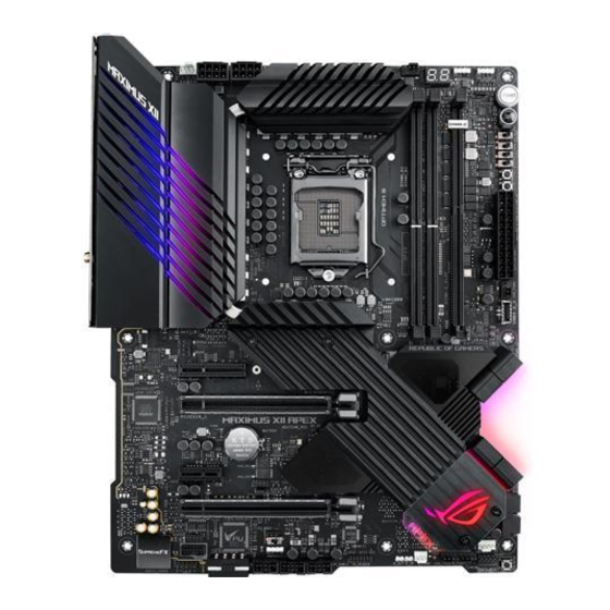
Page 18: Motherboard Layout
Motherboard layout Chapter 1: Product Introduction... - Page 19 29. Thermal Sensor header 1-29 30. Thunderbolt header 1-30 31. Q-Code LED 1-31 32. Q-LEDs 1-32 33. BIOS LED 1-32 34. Condensation Detection LEDs 1-33 35. Storage Device Activity LED 1-33 36. 8-pin Power Plug LED 1-34 ROG MAXIMUS XII APEX...
- Page 20 Contact your retailer immediately if the PnP cap is missing, or if you see any damage to the PnP cap/socket contacts/motherboard components. ASUS will shoulder the cost of repair only if the damage is shipment/ transit-related.
- Page 21 (Double Data Rate 4) memory modules. A DDR4 memory module is notched differently from a DDR, DDR2, or DDR3 module. DO NOT install a DDR, DDR2, or DDR3 memory module to the DDR4 slot. Recommended memory configurations ROG MAXIMUS XII APEX...
- Page 22 (D/C) from the same vendor. Check with the vendor to get the correct memory modules. • Double Capacity DRAM support depends oh the DRAM Models. • Visit the ASUS website for the latest QVL. Chapter 1: Product Introduction...
- Page 23 Expansion slots Unplug the power cord before adding or removing expansion cards. Failure to do so may cause you physical injury and damage motherboard components. Please refer to the following table for the recommended VGA configuration. ROG MAXIMUS XII APEX...
- Page 24 Recommended VGA configuration Slot Description Single VGA Dual VGA PCIe 3.0 x4 Shares bandwidth with M.2_1 (x1/x2/x4) PCIe 3.0 x16_1 PCIe 3.0 x1 PCIe 3.0 x16_2 M.2_1 (PCH) Shares bandwidth with PCIE 3.0 X4 (x1/x2/x4) DIMM.2_1 (PCH) DIMM.2_2 (PCH) • We recommend that you provide sufficient power when running CrossFireX™...
- Page 25 For water cooling kits, connect the pump connector to the W_PUMP+ header. Header Max. Current Max. Power Default Speed Shared Control CPU_FAN Q-Fan Controlled CPU_OPT Q-Fan Controlled CHA_FAN1 Q-Fan Controlled CHA_FAN2 Q-Fan Controlled CHA_FAN3 Q-Fan Controlled W_PUMP+ Full-Speed AIO_PUMP Full-Speed FS_FAN1 Full-Speed FS_FAN2 Full-Speed ROG MAXIMUS XII APEX...
- Page 26 Liquid Cooling System headers The Liquid Cooling System headers allow you to connect sensors to monitor the temperature and flow rate of your liquid cooling system. You can manually adjust the fans and water pump to optimize the thermal efficiency of your liquid cooling system. Chapter 1: Product Introduction 1-10...
- Page 27 • If you want to use two or more high-end PCIe x16 cards, use a PSU with 1000W power or above to ensure the system stability. ROG MAXIMUS XII APEX 1-11...
- Page 28 Optane Technology is supported by M.2_1 when sourced from the PCH. ® Before using Intel Optane memory modules, ensure that you have updated your ® motherboard drivers and BIOS to the latest version from ASUS support website. • M.2 slot supports IRST (Intel Rapid Storage Technology). ®...
- Page 29 ® from the PCH. Before using Intel Optane memory modules, ensure that you have ® updated your motherboard drivers and BIOS to the latest version from ASUS support website. The M.2 SSD module is purchased separately. ROG MAXIMUS XII APEX...
- Page 30 SATA Mode item in the BIOS to [Intel RST Premium with Intel Optane System Acceleration (RAID)]. • Before creating a RAID set, refer to the RAID Configuration Guide. You can download the RAID Configuration Guide from the ASUS website. Chapter 1: Product Introduction 1-14...
- Page 31 The USB 3.2 Gen 1 header allows you to connect a USB 3.2 Gen 1 module for additional USB 3.2 Gen 1 ports. The USB 3.2 Gen 1 header provides data transfer speeds of up to 5 Gb/s. The USB 3.2 Gen 1 module is purchased separately. ROG MAXIMUS XII APEX 1-15...
- Page 32 USB 2.0 header The USB 2.0 header allows you to connect a USB module for additional USB 2.0 ports. The USB 2.0 header provides data transfer speeds of up to 480 Mb/s connection speed. DO NOT connect a 1394 cable to the USB connectors. Doing so will damage the motherboard! The USB 2.0 module is purchased separately.
- Page 33 5V connector is aligned with the 5V header on the motherboard. • The addressable RGB LED strip will only light up when the system is powered on. • The addressable RGB LED strip is purchased separately. ROG MAXIMUS XII APEX 1-17...
-
Page 34: Aura Rgb Header
AURA RGB header The AURA RGB header allows you to connect RGB LED strips. RGB_HEADER PIN 1 +12V G R B 12 V The AURA RGB header supports 5050 RGB multi-color LED strips (12V/G/R/B), with a maximum power rating of 3A (12V). Before you install or remove any component, ensure that the power supply is switched off or the power cord is detached from the power supply. -
Page 35: Bios Switch Button
Safe Boot or turning Aura lighting on or off to the button. This button set to [Reset] by default. You can assign a different function to this button in the BIOS settings. ROG MAXIMUS XII APEX 1-19... -
Page 36: Front Panel Audio Header
Front Panel Audio header The front panel audio header is for a chassis-mounted front panel audio I/O module that supports HD Audio. Connect one end of the front panel audio I/O module cable to this header. We recommend that you connect a high-definition front panel audio module to this connector to avail of the motherboard’s high-definition audio capability. -
Page 37: Ln2 Mode Jumper
Node connector The Node connector allows you to connect a compatible PSU or control a compatible fan extension card. Visit www.asus.com for more information about the devices and the latest compatibility list. ROG MAXIMUS XII APEX 1-21... -
Page 38: Pause Switch
Pause switch The Pause switch allows you to freeze the system at a hardware level, thus allowing you to adjust your system settings under heavy overclocking. Chapter 1: Product Introduction 1-22... -
Page 39: Probeit Measurement Points
Connect one of the probe onto the GND ProbeIt point, then connect the other probe onto another ProbeIt point to measure the corresponding voltage information. The illustration above is for reference only, the actual motherboard layout and measure points may differ by model. ROG MAXIMUS XII APEX 1-23... -
Page 40: Retry Button
POST. RSVD switch The RSVD switch is reserved for ASUS-authorized technicians only. Please ensure the RSVD switch is set to Disabled. Setting this switch to Enabled may result in damages to your system. -
Page 41: Safe Boot Button
The system may crash due to the CPU being unstable when using extreme overclocking settings. Enable the Slow Mode switch during LN2 benching to decrease the processor frequency and stabilize the system, allowing you to keep track of the overclocking data. ROG MAXIMUS XII APEX 1-25... -
Page 42: Start Button
Start button Press the Start button to power up the system, or put the system into sleep or soft-off mode (depending on the operating system settings). The button also lights up when the system is plugged to a power source, indicating that you should shut down the system and unplug the power cable before removing or installing any motherboard component. -
Page 43: System Panel Header
(depending on the operating system settings). • Reset button header (RESET) The 2-pin header allows you to connect the chassis-mounted reset button. Press the reset button to reboot the system. ROG MAXIMUS XII APEX 1-27... -
Page 44: Thermal Sensor Header
Thermal Sensor header The Thermal Sensor header allows you to connect a sensor to monitor the temperature of the devices and the critical components inside the motherboard. Connect the thermal sensor and place it on the device or the motherboard’s component to detect its temperature. -
Page 45: Thunderbolt Header
The Thunderbolt header allows you to connect an add-on Thunderbolt I/O card that supports Intel’s Thunderbolt Technology, allowing you to connect up to six Thunderbolt-enabled devices and a DisplayPort-enabled display in a daisy-chain configuration. The add-on Thunderbolt I/O card and Thunderbolt cables are purchased separately. ROG MAXIMUS XII APEX 1-29... -
Page 46: Q-Code Led
Q-Code LED The Q-Code LED design provides you with a 2-digit error code that displays the system status. • The Q-Code LEDs provide the most probable cause of an error code as a starting point for troubleshooting. The actual cause may vary from case to case. •... -
Page 47: Q-Leds
The Q-LEDs provide the most probable cause of an error code as a starting point for troubleshooting. The actual cause may vary from case to case. BIOS LED The BIOS LEDs indicate which BIOS chip is currently in use. ROG MAXIMUS XII APEX 1-31... -
Page 48: Condensation Detection Leds
Condensation detection LEDs The Condensation detection LEDs will light up when water condensation is detected on the corresponding critical key components (CPU, DRAM, and PCIE). This user- friendly design helps you quickly identify possible damages caused by condensation. The Q LEDs provide the most probable cause of an error code as a starting point for troubleshooting. -
Page 49: Pin Power Plug Led
8-pin Power Plug LED The 8-pin Power Plug LED lights up to indicate that the 8-pin power plug is not connected. ROG MAXIMUS XII APEX 1-33... - Page 50 Chapter 1: Product Introduction 1-34...
-
Page 51: Building Your Pc System
NOT install a CPU designed for LGA1155, LGA1156, and LGA1151 sockets on the LGA1200 socket. • ASUS will not cover damages resulting from incorrect CPU installation/removal, incorrect CPU orientation/placement, or other damages resulting from negligence by the user. ROG MAXIMUS XII APEX... - Page 52 Chapter 2: Basic Installation...
-
Page 53: Cooling System Installation
2.1.2 Cooling system installation Apply Thermal Interface Material to the CPU cooling system and CPU before you install the cooling system, if necessary. To install a CPU heatsink and fan assembly ROG MAXIMUS XII APEX... - Page 54 To install an AIO cooler If you wish to install an AIO cooler, we recommend installing the AIO cooler after installing the motherboard into the chassis. AIO_PUMP/ W_PUMP+ CPU_FAN CPU_OPT Chapter 2: Basic Installation...
-
Page 55: Dimm Installation
2.1.3 DIMM installation To remove a DIMM ROG MAXIMUS XII APEX... -
Page 56: M.2 Installation
2.1.4 M.2 installation • The M.2 rubber pad is optional for when installing a single sided M.2 storage device. Ensure to install the bundled M.2 rubber pad before installing your single sided M.2 storage device. • DO NOT install the bundled OPTIONAL M.2 rubber pads when installing a double-sided... - Page 57 The M.2 is purchased separately. ROG MAXIMUS XII APEX...
-
Page 58: Motherboard Installation
2.1.5 Motherboard installation Place the motherboard into the chassis, ensuring that its rear I/O ports are aligned to the chassis’ rear I/O panel. Place nine (9) screws into the holes indicated by circles to secure the motherboard to the chassis. DO NOT over tighten the screws! Doing so can damage the motherboard. -
Page 59: Atx Power Connection
2.1.6 ATX power connection Ensure to connect the 8-pin power plug. ROG MAXIMUS XII APEX... -
Page 60: Sata Device Connection
2.1.7 SATA device connection Chapter 2: Basic Installation 2-10... -
Page 61: Front I/O Connector
Push the connector until it clicks into place. To install USB 3.2 Gen 1 connector To install USB 2.0 connector USB 3.2 Gen 1 USB 2.0 To install front panel audio connector To install system speaker connector AAFP ROG MAXIMUS XII APEX 2-11... -
Page 62: Expansion Card Installation
2.1.9 Expansion card installation To install PCIe x16 cards To install PCIe x4 cards To install PCIe x1 cards Chapter 2: Basic Installation 2-12... - Page 63 • The TypeC_1 port can support up to 20V devices, and the TypeC_2 port can support up to 9V devices when the 6-pin PCIe power connector is connected. • The Thunderbolt card is sold separately. ROG MAXIMUS XII APEX 2-13...
-
Page 64: Wi-Fi Antenna Installation
2.1.10 Wi-Fi antenna installation Installing the ASUS 2x2 dual band W-Fi antenna Connect the bundled ASUS 2x2 dual band Wi-Fi antenna connector to the Wi-Fi ports at the back of the chassis. • Ensure that the ASUS 2x2 dual band Wi-Fi antenna is securely installed to the Wi-Fi ports. -
Page 65: Removing The Pcb Piece (Optional)
• Please hold the motherboard steady with a tight grip when removing the removable PCB piece. • The removal PCB piece is not covered by the warranty. ROG MAXIMUS XII APEX 2-15... -
Page 66: Bios Update Utility
• Updating BIOS may have risks. If the BIOS program is damaged during the process and results to the system’s failure to boot up, please contact your local ASUS Service Center. Chapter 2: Basic Installation... -
Page 67: Motherboard Rear And Audio Connections
Due to the design of the Intel chipset, all USB devices connected to the USB 3.2 Gen 1 ports are controlled by the xHCI controller. Some legacy USB devices must update their firmware for better compatibility. ROG MAXIMUS XII APEX 2-17... -
Page 68: Audio I/O Connections
* Audio 2, 4, 5.1 or 7.1-channel configuration Headset Port 4-channel 5.1-channel 7.1-channel 2-channel Light Blue Line In Line In Line In Side Speaker Out Lime Line Out Front Speaker Out Front Speaker Out Front Speaker Out Pink Mic In Mic In Mic In Mic In... - Page 69 Connect to 2-channel Speakers Connect to 4-channel Speakers Connect to 5.1-channel Speakers ROG MAXIMUS XII APEX 2-19...
- Page 70 Connect to 7.1-channel Speakers Chapter 2: Basic Installation 2-20...
-
Page 71: Starting Up For The First Time
While the system is ON, press the power button for less than four seconds to put the system on sleep mode or soft-off mode, depending on the BIOS setting. Press the power button for more than four seconds to let the system enter the soft-off mode regardless of the BIOS setting. ROG MAXIMUS XII APEX 2-21... - Page 72 Chapter 2: Basic Installation 2-22...
-
Page 73: Chapter 3: Bios And Raid Support
Knowing BIOS The new ASUS UEFI BIOS is a Unified Extensible Interface that complies with UEFI architecture, offering a user-friendly interface that goes beyond the traditional keyboard- only BIOS controls to enable a more flexible and convenient mouse input. You can easily navigate the new UEFI BIOS with the same smoothness as your operating system. -
Page 74: Bios Setup Program
BIOS setup program Use the BIOS Setup to update the BIOS or configure its parameters. The BIOS screen include navigation keys and brief onscreen help to guide you in using the BIOS Setup program. Entering BIOS at startup To enter BIOS Setup at startup, press <Delete> or <F2> during the Power-On Self Test (POST). -
Page 75: Asus Ez Flash 3
ASUS EZ Flash 3 The ASUS EZ Flash 3 feature allows you to update the BIOS without using an OS-based utility. Ensure to load the BIOS default settings to ensure system compatibility and stability. Select the Load Optimized Defaults item under the Exit menu or press hotkey <F5>. -
Page 76: Asus Crashfree Bios 3
The BIOS file in the motherboard support DVD may be older than the BIOS file published on the ASUS official website. If you want to use the newer BIOS file, download the file at https://www.asus.com/support/ and save it to a USB flash drive. -
Page 77: Raid Configurations
For more information on configuring your RAID sets, please refer to the RAID Configuration Guide which you can find at https://www.asus.com/support, or by scanning the QR code. RAID definitions RAID 0 (Data striping) optimizes two identical hard disk drives to read and write data in parallel, interleaved stacks. - Page 78 Chapter 3: BIOS Setup...
- Page 79 CPU self test failed or possible CPU cache error CPU micro-code is not found or micro-code update is failed Internal CPU error Reset PPI is not available Reserved for future AMI error codes 5C – 5F (continued on the next page) ROG MAXIMUS XII APEX...
- Page 80 Q-Code table Code Description S3 Resume is stared (S3 Resume PPI is called by the DXE IPL) S3 Boot Script execution Video repost OS S3 wake vector call E4 – E7 Reserved for future AMI progress codes S3 Resume Failed S3 Resume PPI not Found S3 Resume Boot Script Error S3 OS Wake Error...
- Page 81 Reserved for ASL (see ASL Status Codes section below) Ready To Boot event Legacy Boot event Exit Boot Services event Runtime Set Virtual Address MAP Begin Runtime Set Virtual Address MAP End Legacy Option ROM Initialization System Reset (continued on the next page) ROG MAXIMUS XII APEX...
- Page 82 Q-Code table Code Description USB hot plug PCI bus hot plug Clean-up of NVRAM Configuration Reset (reset of NVRAM settings) Reserved for future AMI codes B8– BF CPU initialization error System Agent initialization error PCH initialization error Some of the Architectural Protocols are not available PCI resource allocation error.
- Page 83 Notices FCC Compliance Information Responsible Party: Asus Computer International Address: 48720 Kato Rd., Fremont, CA 94538, USA Phone / Fax No: (510)739-3777 / (510)608-4555 Identification of the assembled product: INTEL WI-FI 6 AX200 ® Identification of the modular components used in the assembly:...
- Page 84 Compliance Statement of Innovation, Science and Economic Development Canada (ISED) This device complies with Innovation, Science and Economic Development Canada licence exempt RSS standard(s). Operation is subject to the following two conditions: (1) this device may not cause interference, and (2) this device must accept any interference, including interference that may cause undesired operation of the device.
- Page 85 Tenez cet appareil à distance du ventre des femmes enceintes et du bas-ventre des adolescents. ROG MAXIMUS XII APEX...
- Page 86 ASUS products sold in Vietnam, on or after September 23, 2011,meet the requirements of the Vietnam Circular 30/2011/TT-BCT. Các sản phẩm ASUS bán tại Việt Nam, vào ngày 23 tháng 9 năm2011 trở về sau, đều phải đáp ứng các yêu cầu của Thông tư 30/2011/TT-BCT của Việt Nam.
- Page 87 DO NOT throw the mercury-containing button cell battery in municipal waste. This symbol of the crossed out wheeled bin indicates that the battery should not be placed in municipal waste. Regional notice for California WARNING Cancer and Reproductive Harm - www.P65Warnings.ca.gov ROG MAXIMUS XII APEX...
- Page 88 2014/53/EU. Cijeli di: https://www.asus.com/support/ tekst EU izjave o sukladnosti dostupan je na https://www.asus.com/support/ WiFi yang Beroperasi pada 5150-5350 MHz akan terbatas untuk penggunaan WiFi koji radi na opsegu frekvencija 5150-5350 MHz bit će ograničen na...
- Page 89 MR 18750 ANRT 2019 05/02/2019 2014/53/EU. En https://www.asus.com/support/ está disponible el texto completo de la declaración de conformidad para la UE. La conexión WiFi con una frecuencia de funcionamiento de 5150-5350 MHz...
- Page 90 +1-510-739-3777 +1-510-608-4555 Web site https://www.asus.com/us/ Technical Support Support fax +1-812-284-0883 Telephone +1-812-282-2787 Online support https://qr.asus.com/techserv ASUS COMPUTER GmbH (Germany and Austria) Address Harkortstrasse 21-23, 40880 Ratingen, Germany Web site https://www.asus.com/de Online contact https://www.asus.com/support/Product/ContactUs/ Services/questionform/?lang=de-de Technical Support Telephone (DE) +49-2102-5789557 Telephone (AT)
Need help?
Do you have a question about the ROG MAXIMUS XII APEX and is the answer not in the manual?
Questions and answers