Advertisement
Advertisement
Table of Contents

Related Manuals for Eliwell Coldface EWHT800LX Series


Summary of Contents for Eliwell Coldface EWHT800LX Series
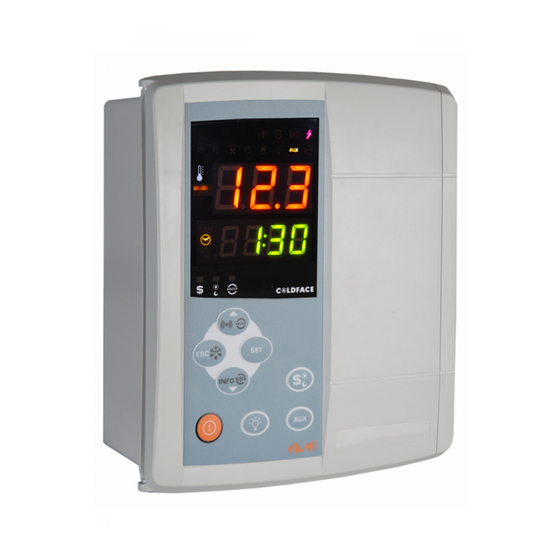
- Page 1 EWHT800LX Controllers for cold rooms and curing rooms for on-board installation...
-
Page 2: Navigation Diagram
INTRODUCTION The Coldface EWHT800LX series controls the temperature and humidity of a static or ventilated cold room. The curing cycle consists of 1 program with 8 customisable climate profiles. The instrument controls positive and negative cold rooms and is capable of managing a double evaporator and con- denser probes. -
Page 3: Electrical Connections
ELECTRICAL CONNECTIONS Output relay (default settings) Digital Inputs (default settings) •OUT1 = Dehumidification • D.I.1 = Door switch •OUT2 = Humidification • D.I.2 = Alarm •OUT3 = Heating • D.I.3 = Low pressure •OUT4 = Compressor • D.I.4 = High pressure •OUT5 = Evaporator fan •OUT6 = Auxiliary 1 (ventilation fans) Analogue Output (default settings) -
Page 4: Upper Display
DISPLAY UPPER DISPLAY • 3 digits and - sign: View: • Operating value • parameters label • alarms, functions 10 9 8 If the upper display is blinking UPPER DISPLAY it means that the value of the lower display can be modified R.H. -
Page 5: User Interface
KEYS press and release press and hold for about 3 seconds Notes •Alarms Menu (always visible)* *HACCP alarms/system alarms p UP • Scroll if present • Increase values • Exit • Manual defrost • Functions menu • Return to Main Menu •... - Page 6 LITE PARAMETER TABLE This section describes the most useful parameters, which are contained in the 'Lite' folder. For a description of all User (USr) and Installer (Ins) parameters, see the user manual. Note: the 'Lite' folder parameters are NOT divided into subfolders and are always visible (no access password is required).
- Page 7 THE INSTRUMENT ENABLES MODIFICATION OF OTHER PARAMETERS DIVIDED INTO USER LEVEL (USr) and INSTALLER LEVEL (InS) How to modify other parameters Installer (InS) level access - User level access is similar: Procedure applies only to more advanced applications. In this case the parameters are arranged in folders (Compressor / Defrost / Fans etc) 1) Press and hold the SET key for 3 seconds until the display shows PAr / Lite 2) Use the UP &...
-
Page 8: Evaporator Fans
band, always positive) and switches off when the value is SEt+db-diF. SEt = 20.0°C Cooling SetPoint; db = 2.0°C temperature intervention half-band, always positive diF = differential = 2.0 COMPRESSOR Digital output OUT4 is configured as compressor relay. The compressor is active if the cold room temperature detected by Pb1 exceeds the value of SP1 + differential diF. - Page 9 CLIMATE PROFILES LED Climate Profiles STEP colour BLINKING individual LED: individual LED ON: duty cycle (STEP) not started individual LED: STEP in progress Note: only one LED can be duty cycle (STEP) not started blinking LED 1,2,.., n (n=2,...7) ON: 1...8 green Climate profile consisting of 2,3,..,7 STEPS...
-
Page 10: Alarms And Troubleshooting
SUPERVISION EWHT800LX can be connected to: Analogue Analogue 0...20mA 0...10V PW Output - AO Output - AO • telecontrol system TelevisSystem (°) 10V 55mA 4..20mA • third-party systems via Modbus protocol (°°) RS 485 39 40 41 39 40 • ParamManager fast parameter setting software Adapter The connection can be made in 2 ways: RS-485... -
Page 11: Alarms Table
ALARMS TABLE This section lists alarms associated with the default configuration of the instrument. For a description of alarms relating to custom configura- tions, refer to the user manual or contact Eliwell Technical Support Folder Cause Effects Remedy Pb1 room probe faulty •... -
Page 12: Technical Support
This section lists alarms associated with the default configuration of the instrument. For a description of alarms relating to custom configura- tions, refer to the user manual or contact Eliwell Technical Support Folder Cause Effects Remedy • End of defrost cycle due to time-out •... -
Page 13: Technical Data
TECHNICAL DATA DESCRIPTION Front panel IP54 Container Bayblend FR 110 Dimensions front 210x245mm, depth 90mm Mounting wall mounting (centre distance of holes A-B 181.0 mm; holes C-D 196.5 mm. See Mechanical Installation paragraph) Connections • removable screw terminals for serial port RS-485, digital and analogue inputs •... - Page 14 Eliwell. Every care has been taken in preparing this document; nevertheless Eliwell declines any liability due to its use. The same applies to any person or company involved in the creation and preparation of this document. Eliwell reserves the right to make aesthetic or func- tional changes at any time without notice.
- Page 15 Facsimile +39 0437 989 066 Sales: +39 0437 986 100 (Italy) +39 0437 986 200 (other countries) saleseliwell@invensyscontrols.com Technical helpline: +39 0437 986 300 E-mail techsuppeliwell@invensyscontrols.com www.eliwell.it 9IS64124-1 - EN - rel. 06/09 © Eliwell Controls s.r.l. 2009 All rights reserved.
Need help?
Do you have a question about the Coldface EWHT800LX Series and is the answer not in the manual?
Questions and answers