Table of Contents
Advertisement
Quick Links
EWRC 300-500 LX
C C
o o
l l
d d
F F
a a
c c
e e
F F
a a
m m
C C
o o
l l
d d
F F
a a
c c
e e
F F
a a
INTRODUCTION
This section is designed to get you up and running in the shortest possible
time. It contains basic information on the EWRC300 – 500LX.
Should you need more detailed information, please refer to the remainder
of the manual.
Out of the box, the EWRC300 – 500LX is set up for standard Electrical
Defrost applications.
It can be altered for Hot Gas or Off Cycle applications if needed.
MECHANICAL ASSEMBLY
a) Remove the coverplate on the right side of the door, pressing lightly on
the points indicated by the arrows in Figure 1 and open the door.
b) Drill holes in the backplate at the top or bottom to pass the wires through.
See the example in figure 2.
c) Screw the backplate to the wall using 4 screws (not supplied) to match the
holes illustrated in Figure 3.
d) Shut the door by securing it with the 2 screws provided.
Replace the screw caps removed earlier from the door (see point a).
1 1
1 1
WIRING DIAGRAM
RS-485
DI1
DI2
Keyboard
1 2 3
11 12 13 14
EWRC 300-500 LX
RS-485/TTL
Line
Neutral
Ground
230V
Line
230V
Neutral
Ground
i i
l l
y y
• Quick Start
m m
i i
l l
y y
2 2
2 2
RS 485
Bus
Adapter
TTL
Pb1
Pb2
Pb3
19 20 21 22 23 24
TTL
Copy
Card
Removable
Connectors
LINE
NEUTRAL
EWRC500LX only
Faston
e) The door lock (an optional accessory) can be installed in 3 different
positions on the door, the holes to be drilled are indicated on the back.
Each position on the door represents a different position where the
disconnector can be mounted.
N.B.: to make it easier to wall mount the backplate, remove the door by pres-
sing lightly on the left side (the side that the door is attached by). You will
also have to separate the base from the keypad by disconnecting the keypad
cable.
3 3
3 3
INPUTS / OUTPUTS DEFAULT SETTINGS
Output relays (default settings)
• Out (relay) 1 = Compressor (or liquid line valve)
• Out (relay) 2 = Defrost
• Out (relay) 3 = Evaporator fan
• Out (relay) 4 = Alarm
• Out (relay) 5 = Light
Note: It is possible to change the function of each relay, see parameters
H21 to H25
Probe Inputs
• Pb1 = Regulation Probe
• Pb2 = Defrost Termination Probe
• Pb3 = Not required (except in special applications)
(EWRC500LX only)
(EWRC500LX only)
Advertisement
Table of Contents

Related Manuals for Eliwell EWRC 500 LX


Summary of Contents for Eliwell EWRC 500 LX
- Page 1 EWRC 300-500 LX • Quick Start INTRODUCTION This section is designed to get you up and running in the shortest possible time. It contains basic information on the EWRC300 – 500LX. Should you need more detailed information, please refer to the remainder of the manual.
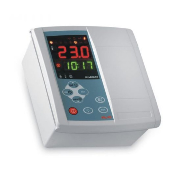
- Page 2 DISPLAY Top Display 3 figures with + /- sign shows: • Process Value • parameters’ labels, • alarms, functions Bottom Display 4 figures shows: • parameters’ value, • function state / other 11 10 9 KEYS TOP DISPLAY press approx press and release Note BOTTOM DISPLAY...
- Page 3 Sales +39 0437 986 100 (Italy) • +39 0437 986 200 (other countries) • E-mail saleseliwell@invensyscontrols.com Technical helpline +39 0437 986 300 • E-mail techsuppeliwell@invensyscontrols.com www.eliwell.it © Eliwell Controls s.r.l. 2008 All rights reserved. cod. 9IS44112-1 - GB - rel. 07/08...
Need help?
Do you have a question about the EWRC 500 LX and is the answer not in the manual?
Questions and answers