Table of Contents
Advertisement
Quick Links
GETTING STARTED GUIDE
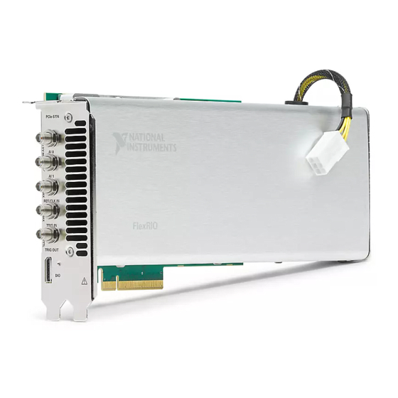
PCIe-5774
12-Bit, 6.4 GS/s, DC-Coupled, 2-Channel PCI FlexRIO Digitizer
Device
This document explains how to install, configure, test, and use the PCIe-5774. You can
program the PCIe-5774 with the following software options.
•
FlexRIO driver software
•
NI LabVIEW Instrument Design Libraries for FlexRIO (instrument design libraries)
Note
Adapter modules are not installable or interchangeable on the PCIe-5774.
Contents
FlexRIO Documentation and Resources...................................................................................2
Verifying the System Requirements..........................................................................................2
Unpacking the Kit..................................................................................................................... 3
PCIe-5774 Kit Contents............................................................................................................ 3
Preparing the Environment....................................................................................................... 3
Installing the Software and Driver............................................................................................ 4
Installing the PCIe-5774........................................................................................................... 4
Installing the Ferrite on the DIO Cable.....................................................................................5
PCIe-5774 Front Panel and Pinout............................................................................................6
Configuring the PCIe-5774 in MAX...................................................................................... 10
FlexRIO Examples.................................................................................................................. 10
Accessing FlexRIO Examples........................................................................................ 10
Block Diagram........................................................................................................................ 11
Component-Level Intellectual Property (CLIP)..................................................................... 13
Making a Measurement with LabVIEW................................................................................. 13
Synchronization...................................................................................................................... 14
Sharing Signals and Triggers with Another PCI Express FlexRIO Device....................15
Sharing Signals and Triggers with PCI Express Devices Using RTSI........................... 15
Troubleshooting...................................................................................................................... 15
What Should I Do if the PCIe-5774 Doesn't Appear in MAX?......................................15
What Should I Do if the PCIe-5774 Fails the Self-Test?................................................ 16
Where to Go Next................................................................................................................... 16
Worldwide Support and Services............................................................................................ 17
Advertisement
Table of Contents

Related Manuals for National Instruments PCIe-5774


Summary of Contents for National Instruments PCIe-5774
-
Page 1: Table Of Contents
GETTING STARTED GUIDE PCIe-5774 12-Bit, 6.4 GS/s, DC-Coupled, 2-Channel PCI FlexRIO Digitizer Device This document explains how to install, configure, test, and use the PCIe-5774. You can program the PCIe-5774 with the following software options. • FlexRIO driver software •... -
Page 2: Flexrio Documentation And Resources
FlexRIO devices. Verifying the System Requirements To use the PCIe-5774, your system must meet certain requirements. For more information about minimum system requirements, recommended system, and supported application development environments (ADEs), refer to the readme, which is available on the software media or online at ni.com/updates. -
Page 3: Unpacking The Kit
PCIe-5774 Getting Started Guide (this document) – PCIe-5774 Safety, Environmental, and Regulatory Information Preparing the Environment Ensure the environment in which you are using the PCIe-5774 meets the following specifications. Operating environment Ambient temperature range 0 °C to 45 °C (Tested in accordance with IEC-60068-2-1 and IEC-60068-2-2. -
Page 4: Installing The Software And Driver
Locate a compatible slot and remove the corresponding slot cover on the computer back panel. Touch any metal part of the computer to discharge any static electricity. Insert the module into the slot you selected. Gently rock the module in to place without forcing it. 4 | ni.com | PCIe-5774 Getting Started Guide... -
Page 5: Installing The Ferrite On The Dio Cable
Connect the 6-pin PCI Express power connector from the power supply to the PCIe-5774. Replace any access panels on the computer case. -
Page 6: Pcie-5774 Front Panel And Pinout
Figure 2. Snap-On Ferrite Bead Installation ™ ™ 1. Molex Nano-Pitch I/O connector 2. Ferrite PCIe-5774 Front Panel and Pinout PCIe-5774 Front Panel The following figure shows the PCIe-5774 front panel. 6 | ni.com | PCIe-5774 Getting Started Guide... - Page 7 Figure 3. PCIe-5774 Front Panel PCIe-5774 AI 0 AI 1 REF/CLK IN TRIG IN TRIG OUT The following table describes the signal connections for the PCIe-5774. PCIe-5774 Getting Started Guide | © National Instruments | 7...
- Page 8 Sample Clock. TRIG IN Standard SMA female connector Analog IN trigger. TRIG OUT Standard SMA female connector Digital OUT trigger. Digital I/O Pinout The following figure shows the Digital I/O (DIO) connector pinout. 8 | ni.com | PCIe-5774 Getting Started Guide...
- Page 9 Notice The maximum input signal levels are valid only when the module is powered on. To avoid permanent damage to the PCIe-5774, do not apply a signal to the device when the module is powered down. MGTs are available only on devices with KU060 FPGAs.
-
Page 10: Configuring The Pcie-5774 In Max
Notice Connections that exceed any of the maximum ratings of any connector on the PCIe-5774 can damage the device and the system. NI is not liable for any damage resulting from such connections. Configuring the PCIe-5774 in MAX Use Measurement & Automation Explorer (MAX) to configure your NI hardware. MAX informs other programs about which NI hardware products are in the system and how they are configured. -
Page 11: Block Diagram
Block Diagram The following figure shows a block diagram of the carrier portion of the PCIe-5774 (KU035 FPGA version). Figure 5. Carrier Block Diagram (KU035) Power Supplies +12 V +5 V +12 V, +3.3 V Gen3 x8 PCIe Flash GPIO +1.8 V... - Page 12 Module Clocking Clk 100 Synchronization Clk 10 DRAM Bank 0 DRAM Bank 1 (2 GB) (2 GB) Reference Clock The following figure shows a block diagram of the I/O portion of the PCIe-5774. 12 | ni.com | PCIe-5774 Getting Started Guide...
-
Page 13: Component-Level Intellectual Property (Clip)
CLIP allows your IP to communicate directly with both the FPGA VI and the external adapter module connector interface. The PCIe-5774 ships with socketed CLIP items that add module I/O to the LabVIEW project. Making a Measurement with LabVIEW Launch LabVIEW. -
Page 14: Synchronization
Reference Clock and triggers between the PCIe-5774 and another PCI Express FlexRIO device. You also can use the compact synchronization cable for PCIe and a RTSI adapter (part number 147008A-01L) to synchronize the PCIe-5774 with a PCI Express device that supports synchronization using RTSI. -
Page 15: Sharing Signals And Triggers With Another Pci Express Flexrio Device
Sharing Signals and Triggers with PCI Express Devices Using RTSI Mount the RTSI adapter on the top of the PCIe-5774 using the attached mounting screws. Install the PCIe-5774 and up to five additional PCI Express devices in one PCI Express backplane. -
Page 16: What Should I Do If The Pcie-5774 Fails The Self-Test
Verify the PCIe-5774 appears in the Device Manager. Under an NI entry, confirm that a PCIe-5774 entry appears. Note If you are using a PC with a device for PXI remote control system, under System Devices, also confirm that no error conditions appear for the PCI-to-PCI Bridge. -
Page 17: Worldwide Support And Services
1 866 ASK MYNI (275 6964). For support outside the United States, visit the Worldwide Offices section of ni.com/niglobal access the branch office websites, which provide up-to-date contact information. PCIe-5774 Getting Started Guide | © National Instruments | 17... - Page 18 NI trademarks. Other product and company names mentioned herein are trademarks or trade names of their respective companies. For patents covering NI products/technology, refer to the appropriate location: Help»Patents in your software, the file on your media, or the National Instruments Patent Notice at . You can find patents.txt ni.com/patents...
Need help?
Do you have a question about the PCIe-5774 and is the answer not in the manual?
Questions and answers