Table of Contents
Advertisement
Quick Links
your ticket to all buses
your ticket to all buses
Instruction Manual
Universal Fieldbus-Gateway
®
UNIGATE
IC - RS
Manual Art.-No.: V3504E
Deutschmann Automation GmbH & Co. KG | Carl-Zeiss-Str. 8 | D-65520 Bad Camberg
Tel:+49 6434 9433-0 | Hotline: +49 6434 9433-33 | Fax: +49 6434 9433-40
www.deutschmann.com
Advertisement
Table of Contents

Subscribe to Our Youtube Channel
Related Manuals for DEUTSCHMANN AUTOMATION UNIGATE IC-RS


Summary of Contents for DEUTSCHMANN AUTOMATION UNIGATE IC-RS
- Page 1 Instruction Manual Universal Fieldbus-Gateway ® UNIGATE IC - RS Manual Art.-No.: V3504E Deutschmann Automation GmbH & Co. KG | Carl-Zeiss-Str. 8 | D-65520 Bad Camberg Tel:+49 6434 9433-0 | Hotline: +49 6434 9433-33 | Fax: +49 6434 9433-40 www.deutschmann.com...
-
Page 2: Table Of Contents
Deutschmann Automation GmbH & Co. KG General introduction ......8 ® The UNIGATE IC ......9 Technical introduction . - Page 3 Deutschmann Automation GmbH & Co. KG 5.2.1 Example-Script ......24 The Debug-interface ......25 Overview of the Debug-interface .
- Page 4 Deutschmann Automation GmbH & Co. KG 13 Accessory ......40 13.1 Adapter RS232 ......40 13.2 Adapter RS485 .
- Page 5 Deutschmann Automation GmbH & Co. KG ® Instruction manual UNIGATE IC - RS V. 2.8 21.4.15...
- Page 6 We would be pleased to receive any improvement proposals which you may have. Copyright Copyright (C) Deutschmann Automation GmbH & Co. KG 1997 – 2015. All rights reserved. This document may not be passed on nor duplicated, nor may its contents be used or disclosed unless expressly permitted.
- Page 7 Deutschmann Automation GmbH & Co. KG ® Instruction manual UNIGATE IC - RS V. 2.8 21.4.15...
-
Page 8: General Introduction
Through the flexible firmware of UNIGATE IC no software-changes are required on the side of the customer! Since 1997 Deutschmann Automation has experience in the field of fieldbus gateways; this ® enormous experience results in the UNIGATE IC as a consistent sequel of this successful product line. -
Page 9: The Unigate ® Ic
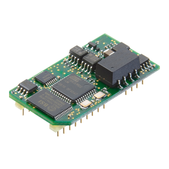
® The UNIGATE IC by Deutschmann Automation contains all components that are required for the communication in a fieldbus in one single module. Therefore a developer does not have to take care for that detail any more, only a hardware redesign is necessary in order to integrate the ®... -
Page 10: Unigate ® Ic Hardware Survey
Deutschmann Automation GmbH & Co. KG The UNIGATE® IC ® UNIGATE IC hardware survey ® The hardware of the UNIGATE IC consists of some few standard components. The picture below shows the functional structure of the IC. ® 21.4.15 Instruction manual UNIGATE... -
Page 11: Hardware Design
Hardware design Deutschmann Automation GmbH & Co. KG Hardware design ® This chapter gives basic advise, that is required in order to load UNIGATE IC into your own ® hardware designs. In the following all ports of UNIGATE IC are described in detail. -
Page 12: Pinout
Deutschmann Automation GmbH & Co. KG Hardware design Pinout Technical specifications Name Description Remark optionally also 3,3V 5V ± 5% < 200mA + 5 V voltage supply available boot enable Logic Load out (SS0-) strobe signal for synchronous, serial interface Driver Data out... -
Page 13: Boot Enable
Hardware design Deutschmann Automation GmbH & Co. KG < 0.3V / 5mA > 1.95V / 10µA < 0.6V / 1mA > 3.8V / 0.1mA Reset Logic < 0.8V / 0.5mA > 1.95V / 10µA < 0.33V / 4mA > 3.8V / 4mA... -
Page 14: Config Mode
The script itself can be generated by the company Deutschmann Automation or with the software Protocol Developer by yourself. For a detailed description of the script.commands of the Protocol Developer see the instruction manual Protocol Developer and the online documentation concerning script-commands. -
Page 15: Connection Examples
After the RS232-driver has been replaced by the UNIGATE IC, the bus is available at the 9-pol. D-sub-socket. Deutschmann Automation is also offering an appropriate adapter board. With it existing devices can be adapted without re-design; see chapter 13 on page 40. Connection examples Here you will find some advise that offers help for a re-design. - Page 16 Deutschmann Automation GmbH & Co. KG Hardware design ® Version 2: Use of UNIGATE IC for digital or analog I/O-modules Out N - M Out 1 - 8 UNIGATE D - Sub Not used Not used ...
- Page 17 Hardware design Deutschmann Automation GmbH & Co. KG The following circuit diagram is an example for how shift register components can be connected to the IC. Version 3: Example for digital I/Os ® The serial synchronous and the asynchronous interface as well can be operated by UNIGATE IC at the same time.
-
Page 18: Layout Examples
Deutschmann Automation GmbH & Co. KG Hardware design Valid for all versions: A planed plug connection of the serial interface in the application offers the possibility of an update of the firmware or the software via an external connection. Layout examples ®... -
Page 19: Unigate ® Ic - Rs232/485
Hardware design Deutschmann Automation GmbH & Co. KG 3.6.2 UNIGATE ® IC - RS232/485 ® Instruction manual UNIGATE IC - RS V. 2.8 21.4.15... - Page 20 Deutschmann Automation GmbH & Co. KG Hardware design The 74HCT595 used in this example has an undefined on-position, but therefor can set the outputs to the tri-state condition via the OutEnable- Pin 13. If it is more important to have a defined on-position in an applica- tion, and the OutEnable-pin is not necessary, the 74HCT594 can be used here.
-
Page 21: Handling (Mounting The Unigate ® Ic On The Carrier Board)
Hardware design Deutschmann Automation GmbH & Co. KG ® Handling (mounting the UNIGATE IC on the carrier board) Depending on the application and the expected shock- and vibration-conditions you can choose ® from the following possibilities for the UNIGATE IC’s installation on the carrier board: ®... -
Page 22: The Serial Interface (To The Host)
IC, the module carries out actions indepen- dently, in order to identify data from the connected device. For customers who already have a software-adaptation at he company Deutschmann Automation, this protocol as well or a script after an adaptation can be processed by the IC. -
Page 23: Synchronous Serial Interface
Synchronous serial interface Deutschmann Automation GmbH & Co. KG Synchronous serial interface ® The synchronous serial interface of the UNIGATE IC is used to connect clocked shift registers or components that have a Serial Peripheral Interface (SPI). It allows •... -
Page 24: Spi Mode
Deutschmann Automation GmbH & Co. KG Synchronous serial interface Set( ShiftRegisterInputBitLength, 16 ); Set( ShiftRegisterOutputBitLength, 16 ); WriteShiftRegister( OutBuffer[0] ); ReadShiftRegister( InBuffer[0] ); // Input data is now in the INBuffer // 0x58 is applied to the outputs of the analog converter... -
Page 25: The Debug-Interface
The Debug-interface Deutschmann Automation GmbH & Co. KG The Debug-interface Overview of the Debug-interface ® The UNIGATE IC features a Debug-interface, that allows a step-by-step processing of a script. Normally this interface is only required for the development of a script. -
Page 26: Script And Configuration
Deutschmann Automation GmbH & Co. KG Script and configuration Script and configuration Overview ® The script stored in the UNIGATE IC, as well as the configuration, can be replaced or updated via the serial interface (application) in the configuration mode. - Page 27 Script and configuration Deutschmann Automation GmbH & Co. KG ® Instruction manual UNIGATE IC - RS V. 2.8 21.4.15...
- Page 28 Deutschmann Automation GmbH & Co. KG Script and configuration The operational sequence is as follows: The Gateway has to be in the config-mode. The script-download is initiated with "Ctrl-P (=0x10)". After that the data follows byte by byte as ASCII-hex-characters.
-
Page 29: Configuration Of The Unigate Ic
Script and configuration Deutschmann Automation GmbH & Co. KG ® Configuration of the UNIGATE ® UNIGATE IC is delivered with an empty script. 7.4.1 Fieldbus RS232/RS485/RS422 • All parameters are set via script. 7.4.2 RS232/RS485/RS422 • RS type: RS232 •... -
Page 30: Generating A Script
Deutschmann Automation GmbH & Co. KG Generating a script Generating a script What is a script? A script is a sequence of commands, that are executed in that exact order. Because of the fact that also mechanisms are given that control the program flow in the script it is also possible to assemble more complex processes from these simple commands. -
Page 31: The Use Of The Protocol Developer
Generating a script Deutschmann Automation GmbH & Co. KG have to be known as fixed values and are not available for the runtime. Another reason for the configuration of the values in WINGATE is the following: After an update of the script these val- ues remain untouched, i. -
Page 32: Script Processing Times
Deutschmann Automation GmbH & Co. KG Generating a script Error[%] = (abs(BaudIst - BaudSoll) / BaudSoll) * 100 In our example the following error results: Error = (abs(9615.38 - 9600) / 9600) * 100 = 0.16% In practise errors below 2% can be tolerated! - Page 33 Generating a script Deutschmann Automation GmbH & Co. KG • Keep the data length at the RS-interface as small as possible. The baud rate is not the problem here, but the amount of characters which are transferred per second. •...
-
Page 34: Fieldbus Rs-Interface
Deutschmann Automation GmbH & Co. KG Fieldbus RS-interface Fieldbus RS-interface ® On the fieldbus RS-side UNIGATE IC - RS physically supports an RS232-, RS485- and RS422- interface. In RS485-operation the wires Rx422 have to be connected to Tx422. The parameter- ization is carried out like at the standard UART via separate script commands. - Page 35 Fieldbus RS-interface Deutschmann Automation GmbH & Co. KG ReadBus ( aBusInBuf[0] , wBusInSize ) ; :Loop; jump :start; ® Instruction manual UNIGATE IC - RS V. 2.8 21.4.15...
-
Page 36: Error Handling At Unigate ® Ic
Deutschmann Automation GmbH & Co. KG Error handling at UNIGATE® IC ® 10 Error handling at UNIGATE A distinction can be made between two categories of system-errors: Serious errors (1-4): In this case, the Gateway must be switched off and switched back on again. -
Page 37: 11 Firmware-Update
Execution of the firmware-update The safest way for the firmware-update is the use of the basis board combined with the software “FDT.EXE“ (firmware-download-tool). These tools are available from Deutschmann Automation (see chapter 13 on page 40). It is also possible to use the description and the tools of the manufacturer of the controller (TEMIC, 89C51RD2) as well. -
Page 38: 12 Technical Data
Deutschmann Automation GmbH & Co. KG Technical data 12 Technical data ® In this chapter you will find all necessary technical data on UNIGATE All measurements in mm. ® 12.1 Mechanics of the UNIGATE 12.1.1 General dimensions of UNIGATE ®... -
Page 39: Technical Data Unigate ® Ic - Rs
Technical data Deutschmann Automation GmbH & Co. KG ® 12.2 Technical data UNIGATE IC - RS Characteristics Explanation Supply voltage 5 V ± 5 %, max. 200 mA DC (optionally 3,3V) Interface 2 UART interfaces, 1 synchronous serial interface Physical separation... -
Page 40: 13 Accessory
The Developer Board was developed so that the fast implementation of the Deutschmann All-in- ® one bus node UNIGATE IC into your electronic system can be guaranteed. The board is suit- able for all Fieldbuses and Industrial Ethernet Buses supported by Deutschmann Automation. ® 21.4.15 Instruction manual UNIGATE... -
Page 41: Quick Start
Accessory Deutschmann Automation GmbH & Co. KG ® The required UNIGATE IC / ICs are ordered separately. The required voltage (5V or 3.3V, depending on the version) can be adjusted. An RS232-interface or a USB-connection is avail- able for the connection to the PC (Debug-interface). -
Page 42: 14 Appendix
Deutschmann Automation GmbH & Co. KG Appendix 14 Appendix 14.1 Explanations of the abbreviations General Product group CL (Compact Line) Product group CM (CANopen Line) Product group CX Product group EL (Ethernet Line) Product group FC (Fast Connect) Galvanic separation RS-side Housing color gray... -
Page 43: Basis Board
Appendix Deutschmann Automation GmbH & Co. KG Profinet-IO PBDP ProfibusDP ® PBDPL ProfibusDP-version L (see comparison table UNIGATE IC for the respective product) ® PBDPX ProfibusDP-version X (see comparison table UNIGATE IC for the respective product) PBDPV0 = ProfibusDPV0 PBDPV1 =... - Page 44 Deutschmann Automation GmbH & Co. KG Appendix Slot X 1 (ZIF-socket) PIN 1 of the IC is located up at the lever of the ZIF-socket. Never place the IC into the socket back to front! Signal Pin 1 24 V DC...
- Page 45 Appendix Deutschmann Automation GmbH & Co. KG P 11 Force Boot. By setting this bridge the Pin BE is dragged to Ground. For the function see chapter 11.2.1. P 13 Status signal of the IC Plug connector P 13 Signal...
- Page 46 Deutschmann Automation GmbH & Co. KG Appendix P 15, SW1H, SW1L Input shift register Basically the same applies as for P 14, with the exception that different input bits of the shift reg- isters are wire. Connection Meaning P 12 Input 1 ..
-
Page 47: Connectors Of The Basis Board
Appendix Deutschmann Automation GmbH & Co. KG SW1H, SW1L, SW5H, SW5L The rotary switches SW1H, SW1L, SW5H, SW5L are plugged into the base boards and can be removed if required. As a default the rotary switches are plugged in and can be read in through the basis board’s shift registers base boards (see also chapter 5 for it). -
Page 48: Rs Fieldbus Connector
Deutschmann Automation GmbH & Co. KG Appendix Not connected Not connected Rx / Diag Receive signal Debug interface Attention: In case the RS-interface is NOT potentially divided, "GND" and "supply 0V" are connected internally. Pin assignment P2 (2-pin screw-type/plug connector) Pin No. -
Page 49: Slide Switch (Rs485 Termination)
Appendix Deutschmann Automation GmbH & Co. KG 14.2.2.7 Slide switch (RS485 termination) If the gateway is operated as the first or last physical device in the RS485 bus, there must be a bus termination at this gateway. In order to do this, either a bus terminating resistor in the con- nector or the resistor (150) integrated in the gateway must be activated. -
Page 50: Wiring Diagram Unigate ® Ic-Basis Board Rs
Deutschmann Automation GmbH & Co. KG Appendix 14.2.3 Wiring diagram UNIGATE ® IC-basis board RS ® 21.4.15 Instruction manual UNIGATE IC - RS V. 2.8... - Page 51 Appendix Deutschmann Automation GmbH & Co. KG ® Instruction manual UNIGATE IC - RS V. 2.8 21.4.15...
- Page 52 Deutschmann Automation GmbH & Co. KG Appendix ® 21.4.15 Instruction manual UNIGATE IC - RS V. 2.8...
-
Page 53: 15 Representation Of The Data On The Fieldbus Rs-Side
Representation of the data on the fieldbus RS-side Deutschmann Automation GmbH & Co. KG 15 Representation of the data on the fieldbus RS-side Data on the fieldbus-side can be read and written with the following script commands: • ReadBus •... - Page 54 Deutschmann Automation GmbH & Co. KG Representation of the data on the fieldbus RS-side Software/ProtocolDeveloper/Example exampl_IC_RS_ModbusMaster.dss ® 21.4.15 Instruction manual UNIGATE IC - RS V. 2.8...
-
Page 55: 16 Servicing
Servicing Deutschmann Automation GmbH & Co. KG 16 Servicing Should questions arise that are not covered in this manual you can find further information in our • FAQ/Wiki area on our homepage www.deutschmann.com or directly in our Wiki on www.wiki.deutschmann.de... -
Page 56: 17 Ec Declaration Of Conformity
EC declaration of conformity 17 EC declaration of conformity EC declaration of conformity As defined by EC-EMC-Directive Hereby we, company Deutschmann Automation GmbH & Co. KG Carl-Zeiss-Straße 8 D-65520 Bad Camberg Tel: +49 (0)6434 / 9433-0 Fax: +49 (0)6434 / 9433-40 declare that the below mentioned product was developed, produced and put on the market in accordance with the above EC-Directive.
Need help?
Do you have a question about the UNIGATE IC-RS and is the answer not in the manual?
Questions and answers